HAL Id: hal-00518283
https://hal.archives-ouvertes.fr/hal-00518283
Submitted on 16 Sep 2010HAL is a multi-disciplinary open access archive for the deposit and dissemination of sci-entific research documents, whether they are pub-lished or not. The documents may come from teaching and research institutions in France or abroad, or from public or private research centers.
L’archive ouverte pluridisciplinaire HAL, est destinée au dépôt et à la diffusion de documents scientifiques de niveau recherche, publiés ou non, émanant des établissements d’enseignement et de recherche français ou étrangers, des laboratoires publics ou privés.
Ultracompact and unidirectional metallic antennas
N. Bonod, A. Devilez, Brice Rolly, Sebastien Bidault, B. Stout
To cite this version:
N. Bonod, A. Devilez, Brice Rolly, Sebastien Bidault, B. Stout. Ultracompact and unidirectional metallic antennas. Physical Review B: Condensed Matter and Materials Physics (1998-2015), Ameri-can Physical Society, 2010, 82 (11), pp.115429. �10.1103/PhysRevB.82.115429�. �hal-00518283�
APS/123-QED
Ultracompact and unidirectional metallic antennas
Nicolas Bonod1,∗, Alexis Devilez,1 Brice Rolly,1 Sebastien Bidault,2 Brian Stout1 1Institut Fresnel, CNRS UMR 6133,
Aix-Marseille Universit´e, Ecole Centrale Marseille,
Domaine Universitaire de Saint J´erˆome, 13397 Marseille, France
and
2Institut Langevin, CNRS UMR 7587,
ESPCI ParisTech, 10 rue Vauquelin, 75231 Paris cedex 05, France
∗
(Dated: August 19, 2010)
Abstract
We investigate the angular redistribution of light radiated by a single emitter located in the vicinity of dipolar silver nanoparticles. We point out the fundamental role of the phase differences introduced by the optical path difference between the emitter and the particle and demonstrate that the polarizability of the metallic nanoparticle alone cannot predict the emission directional-ity. In particular, we show that collective or reflective properties of single nanoparticles can be controlled by tuning the distance of a single emitter at a λ/30 scale. These results enable us to design unidirectional and ultracompact nanoantennas composed of just two coupled nanoparticles separated by a distance achievable with biological linkers.
I. INTRODUCTION
Metallic nanostructures are key elements in the control of light interaction with quantum emitters. They can both focus light in tiny volumes and enhance the radiative decay rates of nearby emitters.1–9 The latter property has been thoroughly studied in the case of a single emitter coupled to a single nanoparticle.10–20 It has been shown that the radiative
decay rates depend strongly on the distance between the emitter and the nanoparticle. Furthermore, at very short distances from the surfaces (a few nanometers), non radiative decay channels dominate and the quantum efficiency drops. The coupling efficiency between emitters and optical antennas also depends on the orientation of the dipolar source with respect to the dipolar modes supported by the metallic particles. A longitudinal coupling geometry significantly enhances the emission decay rates while a transverse interaction leads to moderate enhancements.19–22
More recently, the ability of nanoantennas to control the angular emission of single molecules has been investigated.23–25 This possibility is particularly important since a high
directivity facilitates both the excitation of a quantum emitter by a collimated beam as well as the collection of the radiated light.26 Yagi-Uda antennas have been successfully introduced at optical frequencies27,28 and their high angular directivity has recently been
confirmed experimentally.29 This antenna geometry combines a director element generally
consisting of a finite chain of identical particles and a reflector element typically based on a slightly larger particle.30,31 A dipolar emitter can be coupled longitudinally to the antenna
by utilizing a nanoparticle located near the reflector element.32 In this configuration, the emitter is off-axis. For an on-axis emitter, the weak transverse coupling with the chain of particles can be reinforced by employing the so-called ‘super emitter’consisting of a dimer of nanoparticles perpendicular to chain axis.12,31 Pakizeh et al. have recently proposed an ultracompact antenna made of two identical metallic particles.32The dipolar emitter is then
coupled to a dark mode characterized by opposite phase dipolar modes induced in the two neighboring particles. In that case, it has been shown that the emitter radiates predomi-nantly in only one half space and can thus be characterized as unidirectional.
This paper is dedicated to studying how nearby spherical nanoparticles modify the angu-lar distribution of light emitted by an oscillating dipole. In particuangu-lar, we provide a thorough study of the phase differences between the dipolar source and the dipolar mode induced in
the particle. We emphasize that these phase differences must take into account the optical path between the emitter and the particle in addition to the polarizability of the particle. We show that by tuning the position of a single emitter from a single nanoparticle by a few tens of nanometers, we can sufficiently modify the dephasing to control the reflective or collective properties of the particle at a given frequency. When the phase difference between the exciting and induced dipoles is strictly equal to π, an equal part of the energy is radiated into each of the half spaces surrounding the emitter (the separation plane being perpendic-ular to the axis containing the dipoles). We then apply these results to the design of highly unidirectional antennas composed of two nanospheres separated by a mere 50 or 60 nm. The basic concept is similar to the idea underlying the design of Yagi-Uda optical antennas, which associate the collective and reflective properties of nanoparticles,27,28 but at much
smaller interparticle distances and in simpler geometries. Taking into account the phase lag induced by the distance between the emitter and the nanoparticle, highly directional antennas can be designed with only two nanoparticles. We will first emphasize the role of the distance between the emitter and the nanoparticles by designing a directional antenna composed of identical particles, i.e. with strictly identical polarizabilities. Furthermore, by tuning the relative size of the two particles, it is possible to design an antenna smaller than
λ/2 that channels light radiated by a single emitter in the angular aperture of commercial
microscope objectives.33
II. RADIATION PROPERTIES OF A DIPOLAR EMITTER COUPLED TO A SINGLE NANOPARTICLE
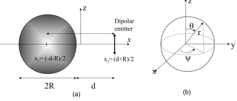
We first investigate the radiation pattern of a single emitter located near a single 90 nm silver particle. The dipolar emitter is polarized along the z-axis in order to provide a trans-verse coupling with the nanoparticle as sketched in Fig. 1. The emission properties of the dipolar emitter are calculated in the framework of rigorous Lorentz-Mie theory, and com-bined with multiple scattering theory in configurations where more than one silver particle is present.34–36 This analytical method is particularly well suited to tackle light scattering
by an ensemble of nanospheres. In order to insure an accurate modeling of the short range couplings, the calculations presented in this study are carried out with 30 multipole orders. Nevertheless, let us emphasize that the electromagnetic response of the metallic particles
under consideration is predominately dipolar in nature, resulting in a rapid multipole con-vergence. Consequently, a dipole approximation (1st order) would qualitatively exhibit all the underlying physics observed in this work.
The radiation patterns are obtained from the radial component of the Poynting vector in the far field. In order to estimate how much light is collected or reflected by the metallic particle, we define the reflection coefficient R as the ratio of the power emitted in the x≥ 0 hemisphere with respect to the total radiated power.
FIG. 1. (a) Sketch of a dipolar emitter oriented along the z-axis and located at a distance d from the surface of a silver nanosphere. The refractive index of silver is taken from Ref. 37. Silver nanospheres are embedded in a polymer of refractive index 1.5. (b) The spherical coordinates used in the analytical expressions.
In this work, we pay particular attention to the dephasing between the emitting and in-duced dipoles. When the dipole approximation dominates (as it does here), it is sufficient to calculate the electric field at the center of the metallic particle. The induced dipole moment of the nanoparticle is then obtained by multiplying the total electric field by Vsϵ0(εs− εb)
where Vsis the volume of the sphere, ϵ0 the permittivity of vacuum and εsand εb are the
rel-ative permittivities of the metal and the background media respectively. For small particles, the quasi-static approximation applies and we can express the resulting phase differences as the sum of the phase differences due to the optical path difference field from the emitter and the polarizability of the particle. It must be stressed that in previous works, attention was focused on the phase difference of a nanoparticle polarizability with respect to its local excitation fields, while in this work we emphasize importance of taking into account the additional phase difference induced by the (small but non-negligible) optical path between
the emitter and the nanoparticle. We point out that we chose the common convention of the phase differences defined to lie in the range from -π to π.
0.0 0.2 0.4 0.6 0.8 1.0 0 30 60 90 120 150 180 210 240 270 300 330 0.0 0.2 0.4 0.6 0.8 1.0 0.3 0.4 0.5 0.6 0.7 0.8 0.9 -1.3π -1.0π -0.8π -0.5π -0.30.0π π 0.3π 0.5π 0.8π 1.0π 1.3π λ (µm) ∆Φ 0.3 0.4 0.5 0.6 0.7 0.8 0.9 1.0 Re fle ct ed e ffi cie nc y 0.0 0.2 0.4 0.6 0.8 1.0 0 30 60 90 120 150 180 210 240 270 300 330 0.0 0.2 0.4 0.6 0.8 1.0 (a) (b) (c)
FIG. 2. (a) A dipolar emitter oriented along the z-axis is located at a distance d = 30 nm from a silver sphere of diameter 90 nm. The phase difference between the emitting and induced dipoles (circles, left scale) and reflection efficiency (right scale. Full line: complete calculation, triangles: dipolar approximation) as a function of the emission wavelength. Emission patterns of the oscillating dipole at (b) λ = 510 nm and (c) λ = 600 nm in the xOz plane, (d = 30 nm) calculated by plotting the radial component of the Poynting vector normalized by the forward emitted value as a function of the polar angle.
The phase differences ∆ϕ between the emitter and dipole moment of a (D = 90 nm) silver nanoparticle are displayed in Fig. 2 (circles) as a function of the emission wavelength. The emitting and induced dipoles are precisely in opposing phase at λr = 600 nm, ∆ϕ = π,
and remain roughly in opposite phase for longer wavelengths. For wavelengths smaller than
λr = 600 nm, ∆ϕ varies as a function of λ, and the induced dipole is generally
out-of-phase with respect to the emitter. The out-of-phase of the polarizability of the nanoparticle is also displayed (squares) and the phase value of π/2 at λ = 500 nm indicates the plasmon resonance. Let us now investigate the radiation properties of the coupled system in terms of the reflection efficiency of the nanosphere. We present in Fig. 2 the reflection efficiency, R,
of the nanoparticle (i.e. defined as the power emitted in the x≥ 0 half space over the total emitted power) as a function of the emission wavelength λ. When the reflection efficiency is lower than 0.5, the dipole preferentially radiates towards the x ≤ 0 half space and the nanoparticle behaves as a collector (c.f. Fig. 1: the nanoparticle is located on the negative
x-axis). The full line in Fig. 2 clearly indicates that depending on the phase differences
between the emitting and induced dipoles, a metallic nanoparticle can either collect or reflect light radiated by a single emitter. Let us mention that the dipolar approximation (triangles) exhibits almost all the features of the radiation properties, meaning that the coupling between the single emitter and the metallic particle is almost perfectly dipolar for
λ > 450 nm. For wavelengths λ > λr, the emitting and induced dipoles are nearly opposite
in phase and the emitter radiates preferentially towards the metallic nanoparticle with R dropping down to 0.4 at λ = 665 nm. For λ < λr, the emitting and induced dipoles are
out-of-phase and the nanoparticle reflects with a rather high efficiency the radiated light since R reaches 90% at λ = 510 nm.
The emission pattern of the light radiated by the exciting dipole at λ = 510 nm is recon-structed in Fig. 2(b) by plotting the radial component of the Poynting vector normalized by the forward emission value as a function of the polar angle (in the plane xOz). This result demonstrates the good unidirectionality offered by a single nanoparticle. The angular width of the emission pattern defined as the angle between the on-axis maximum value and the direction of half maximum value is of the order of ±40 degrees. Finally, it is interesting to note that for λ = λr, the ratio of the radiated energy in both half spaces is precisely equal
to 1. It may seem surprising that a highly asymmetric environment (a single particle at the left of the emitter) results in perfectly symmetric radiation (see the radiation pattern in Fig. 2(c)). To fully understand this counter-intuitive result, let us consider the analytic expression of the emission of two dipoles with moments denoted p1 and p2. They are placed
along the x-axis with separation d + a, and oriented along the z-axis (see Fig. 1(a)). Let us note x1 = −(d + a)/2 and x2 = (d + a)/2 the positions of the dipoles along the x-axis.
We consider that in the far-field limit (r ≫ λ), |r − xj| − r =
√
(x− xj)2+ y2+ z2 − r ≈
produced in the far field by p1 (j = 1) and p2 (j = 2) then write : Ej(r, θ, φ) = (ω c )2 1 4πrϵ0 eik|r−xj|[(e r×pj)× er] (1) = (ω c )2 1 4πrϵ0
eikre−ikxjsin(θ) cos(φ)p
j sin(θ)(−eθ) (2)
Hj(r, θ, φ) =
kω
4πre
ikre−ikxjsin(θ) cos(φ)p
j sin(θ)(−eφ) (3)
with er, eθ, and eφ the unit vectors of the spherical basis (Fig. 1(b)). The resulting far-field,
time-averaged Poynting vector of the sum of these fields writes :
P(r, θ, φ) = 1 2 Re[(E1+ E2) ∗× (H 1+ H2)] (4) = ω 3k 32π2ϵ 0c2r2
(p∗1e−ikreikx1sin(θ) cos(φ)+ p∗
2e−ikre
ikx2sin(θ) cos(φ)) (5) (p1eikre−ikz1sin(θ) cos(φ)+ p2eikre−ikz2sin(θ) cos(φ)) sin2(θ) er
= ω 3k 32π2ϵ 0c2r2 [ |p1|2+|p2|2+ 2 Re(p1p∗2e
ik(d+a) sin(θ) cos(φ))]sin2(θ) e
r (6)
To study the symmetry of the radiation pattern, we compute the sum of the Poynting vectors in one direction and in the opposite direction :
∆P(r, θ, φ) = P(r, θ, φ) + P(r, π− θ, φ + π) (7)
= ω
3k
16π2ϵ 0c2r2
Re{2ip1p∗2sin[k(d + a) sin(θ) cos(φ)]} sin 2(θ) e
r (8)
In our case, we are interested by the evolution of ∆P with respect to the relative phase
ϕ = ϕ1− ϕ2 between p1 =|p1|eiϕ1 and p2 =|p2|eiϕ2 :
∆P(r, θ, φ) = ω
3k
16π2ϵ 0c2r2
{−2|p1||p2| sin(ϕ) sin[k(d + a) sin(θ) cos(φ)]} sin2(θ) er (9)
Hence when ϕ = kπ with k ∈ N, ∆P = 0 for any value of the dipolar amplitudes |p1| and
|p2|. This calculation demonstrates that when the emitted and induced dipoles are in phase
or in opposite phase, the emission from the two dipoles is perfectly symmetric with respect to the origin, while the electromagnetic environment of the emitter can be highly asymmetric. This confirms that the wavelength of the plasmonic resonance (λ = 500 nm) taken alone cannot predict the directionality of the emission and that the distance between the emitter and the nanoparticle plays a crucial role. Moreover, this model exhibits a very interesting property: in a given direction defined by θ and ϕ, the change of the sign of sin(ϕ) will change the sign of ∆P, for every distance d. In order to confirm this assumption, phase differences
500 600 700 800 20 40 60 80 100 -1 -0.9 -0.7 -0.6 -0.5 -0.4 -0.2 -0.1 0 0.1 0.3 0.4 0.5 0.6 0.8 0.9 1 λ (nm) d (n m ) 1.0 1.0 500 600 700 800 20 40 60 80 100 0.10 1.0 1.8 2.7 3.6 4.4 5.3 6.2 7.1 7.9 8.8 9.7 11 11 12 13 14 λ (nm) d (n m ) 500 600 700 800 20 40 60 80 100 -1 -0.9 -0.7 -0.6 -0.5 -0.4 -0.2 -0.1 0 0.1 0.3 0.4 0.5 0.6 0.8 0.9 1 λ (nm) d (n m ) 1.0 1.0 500 600 700 800 20 40 60 80 100 0.10 1.0 1.8 2.7 3.6 4.4 5.3 6.2 7.1 7.9 8.8 9.7 11 11 12 13 14 λ (nm) d (n m ) (a) (b) (c) (d)
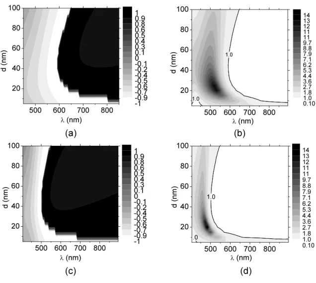
FIG. 3. (a) Phase differences normalized by π between the dipolar emitter and the induced dipolar moment of the nanoparticle and(b) reflection efficiency as a function of the wavelength of emission and the distance d between the emitter and the metallic surface of a 90 nm silver sphere. Figs. (c) and (d) show similar results as (a) and (b) respectively but for a 60 nm sphere.
(Fig. 3(a)) and reflection efficiencies (Fig. 3(b)) are now displayed as a function of distance d and λ. These graphs confirm the clear correlation between reflection efficiency and the phase differences of the emitting and induced dipoles. The isoefficiency line is plotted in Fig. 3(b) when the directionality is null and it matches the isodephasing line (see Fig. 3(a)) plotted for ∆ϕ = π. Calculations performed for a 60 nm silver particle (Fig. 3(c)-(d)) show that a similar behavior is obtained, but that the opposite-phase wavelength, λr, is shifted towards
shorter wavelengths. These graphs evidence that in the 500 nm - 600 nm range (with d = 30nm), the smaller particles (60 nm) mostly collect electromagnetic radiation while larger
particles (90 nm) act as reflectors. This property allows the design of Yagi Uda antennas with a reflector made of slightly larger particles and a collector made of an array of identical smaller particles.27–31More importantly, these calculations show that at a given frequency, a
single sphere can act as a reflector or a collector depending on its distance from the emitter, and that this behavior can be controlled inside a very small range of distances (a few tens of nm). For example, we can observe in Fig. 3(d) that at λ = 550 nm, the nanoparticle behaves as a collector when it is at a distance of 40 nm from the emitter while it behaves as a reflector when this distance is reduced to 10 nm. Consequently, it is possible to design unidirectional antennas by assembling two identical particles, i.e. with identical polarizabilities and by tuning the distances between the emitter and both particles. However, Fig. 3 suggests that a stronger directionality can be achieved by assembling two particles of different diameters with minimum and maximum reflection efficiencies at the emission wavelength, property that cannot be achieved with equal diameters. We can thus design an ultracompact antenna made of 90 nm and 60 nm particles at an equal 30 nm distance from the emitter, geometry chosen to optimize the dephasing between the dipolar moments of the nanospheres and the emitter.
III. ULTRACOMPACT AND UNIDIRECTIONAL NANOANTENNA
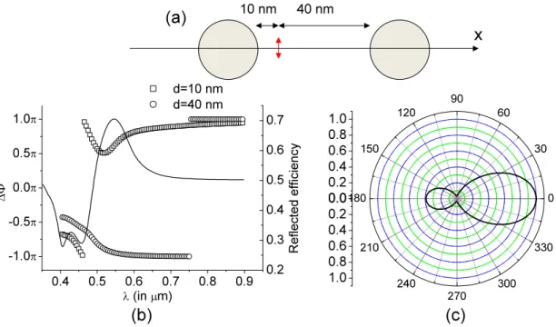
Before discussing antennas with non equal diameters, let us begin this section by designing an ultracompact antenna composed of two identical nanoparticles of diameters 60 nm closely separated by a distance of only 50 nm. The emitter is located at 10 nm from the first particle (which thus acts as the reflector) and 40 nm from the second particle (the collector) (see Fig. 4a). Fig. 4b shows the reflection efficiency as a function of the wavelength of emission. A good directivity can thus be achieved with strictly identical particles since 70% of the emitted energy is radiated in the positive x half space. Let us note that both distances, respectively 10 nm and 40 nm are much smaller than the emitting wavelength and achievable with biological linkers.7,18
Let us now design an asymmetric antenna made of two silver particles with different diameters to optimize their reflective and collective properties. The antenna, consisting of 60 nm and 90 nm diameter silver spheres, was optimized with respect to the particle sizes while keeping d equal to 30 nm (see Fig. 5(a)). In a first step, we compute the phase differences
0.4 0.5 0.6 0.7 0.8 0.9 -1.0π -0.5π 0.0π 0.5π 1.0π d=10 nm d=40 nm ∆Φ λ (in µm) 0.2 0.3 0.4 0.5 0.6 0.7 R ef le ct ed e ffi cie nc y 0.0 0.2 0.4 0.6 0.8 1.0 0 30 60 90 120 150 180 210 240 270 300 330 0.0 0.2 0.4 0.6 0.8 1.0 (b) (c) x (a) 10 nm 40 nm
FIG. 4. (a) The nanoantenna is composed of two identical silver nanoparticles of diameter 60 nm. The emitter is located at 10 nm from the left particle, and at 40 nm from the right particle. (b) Reflection efficiency as a function of the emitted wavelength. (c) Emission pattern of the oscillating dipole at λ = 550 nm in the xOz plane.
between the emitter and the two induced dipolar modes supported by the particles. The wavelength range in which one particle acts as a collector while the other reflects radiation exceeds 100 nm, which is larger than the width of a typical fluorescent emitter. Fig. 5(b) shows that this antenna geometry fulfills these conditions for wavelengths ranging from 475 nm to 600 nm. As expected, the ratio of the radiated power towards the x≥0 half space is maximum when the phases are of opposite sign, and it can reach more than 97% at λ = 520 nm. The emission pattern is reconstructed in Fig. 5(c) at λ = 520 nm as a function of the polar angle (in the plane xOz). It confirms the high unidirectionality of this antenna since the emitted power towards the left half plane is unobservable at this scale. Moreover, this antenna narrows the angular redistribution of emitted light compared to a single nanoparticle since the angular width of the emission cone is less than±30 degrees. Such angular openings are easily achievable with commercial microscope objectives33. In practice, this asymmetric
nanoantenna, although much smaller than the vacuum emission wavelength of the oscillating dipole, is almost perfectly unidirectional. For the sake of completeness, the evolution of the radiative and total decay rates and the quantum efficiency of the emitter in the vicinity of
0.4 0.5 0.6 0.7 0.8 -1.0π -0.5π 0.0π 0.5π 1.0π D = 90 nm D = 60 nm λ (in µm) ∆φ 1 , ∆φ 2 0.4 0.5 0.6 0.7 0.8 0.9 1.0 Re fle ct ed e ffi ci en cy 0.0 0.2 0.4 0.6 0.8 1.0 0 30 60 90 120 150 180 210 240 270 300 330 0.0 0.2 0.4 0.6 0.8 1.0 (b) (c) x (a) (d) 0.4 0.5 0.6 0.7 0.8 0.0 0.5 1.0 1.5 2.0 2.5 3.0 R ad ia tiv e an d to ta l d ec ay ra te s λ (in µm) 0.4 0.5 0.6 0.7 0.8 0.9 Q ua nt um e ffi ci en cy 30 nm 30 nm
FIG. 5. (a) The nanoantenna is composed of silver particles of diameter 60 nm and 90 nm. The emitter is located at 30 nm from both particles. (b) Full line, right scale: Reflection efficiency as a function of the emitted wavelength; Dotted and dashed lines, left scale: dephasing of the emitting and induced dipoles supported by spheres of diameter 90 nm (dashed line) and 60 nm (dotted line). (c) Emission pattern of the oscillating dipole at λ =550 nm in the xOz plane. (d) Full and dashed lines, left scale: radiative (dashed line) and total (full line) decay rates enhancements as a function of the wavelength emission. Full line+squares, right scale: quantum efficiency (the intrinsic quantum efficiency is equal to 1).
the optical antenna are displayed in Fig. 5(d). For that purpose, the total emitted power,
Ptot, and the radiated power, P , are calculated by integrating the radial component of the
Poynting vector over a spherical surface surrounding the source, at respective distances of 1 nm and 50 µm. The total (Γtot) and radiative (Γrad) decay rate enhancements are then
0.4 0.5 0.6 0.7 0.8 0 500 1000 1500 2000 2500 3000 3500 Γto t , Γra d λ (µm) 0.4 0.5 0.6 0.7 0.8 0.0 0.1 0.2 0.3 0.4 0.5 0.6 Q ua nt um e ffi ci en cy η λ (in µm) 0.0 0.2 0.4 0.6 0.8 1.0 1.2 0 30 60 90 120 150 180 210 240 270 300 330 0.0 0.2 0.4 0.6 0.8 1.0 1.2 z x (a) (b) (c) (d)
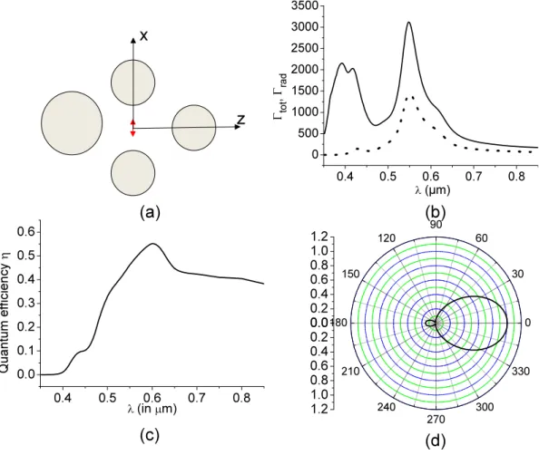
FIG. 6. (a) Sketch of the ultracompact nanoantenna + super emitter: the dipolar source is longitudinally coupled with two 60 nm silver particles on the z axis, with an emitter-particle distance of 8 nm. The emitter-particle distances on the x axis are equal to Fig. 5(a) at 30 nm. (b) Radiative and total decay rate enhancements as a function of the emission wavelength. (c) Quantum efficiency as a function of the emission wavelength. (d) Emission pattern of the oscillating dipole at λ =610 nm in the xOz plane.
power (P0) in the homogeneous background medium: Γtot = Ptot/P0 and Γrad = Prad/P0.
The quantum efficiency is then defined as η = Γrad/(Γtot+(1−ηi)/ηi) where ηiis the intrinsic
quantum efficiency. We consider in this work a perfect emitter (ηi = 1). Fig. 5(d) shows that
the high directionality achieved at λ = 520 nm is not associated with a drop of the radiative decay rates which confirms that it relies on the association of the reflective and collective features of nanoparticles rather than on opposing phases between the induced dipoles of the nanoparticles.32The radiative decay rates obtained are comparable with those observed when dealing with Yagi-Uda antennas30,31 and they are significantly enhanced by coupling
the source dipole to a ”super-emitter” as shown in Fig. 6(a). In this last case, we consider a more complex antenna geometry to combine unidirectionality and strong radiative rate enhancements by introducing two dipolar particles coupled longitudinally to the emitter. Fig. 6(b) shows that a super emitter can strongly enhance the radiative decay rates by up to 3 orders of magnitude. In particular, at λ = 610 nm, the quantum yield is maximum, the radiative decay rate is enhanced by more than 500 and the unidirectionality is preserved as shown on Fig. 6(d).
IV. CONCLUSION
The reflection or collection behavior of the nanoparticle depends on the total phase dif-ference between the emitting and induced dipoles which includes both the polarizability of the metallic particle and the optical path between the emitter and the nanoparticle. We showed the importance of the role of the optical path between the emitter and a metallic particle on the redistribution of light for distances smaller than λ/30. One consequences of this observation was to remark that when the emitting and induced dipoles are exactly in opposing phase, the ratio between the radiated powers in the backward and forward direc-tions is precisely equal to unity. We unveiled the importance of the optical path by designing a directional antenna composed of two identical nanoparticles. The reflective and collective properties were tuned by controlling the distance between the emitter and the nanoparticles at a scale of λ/30. We also presented a means to design highly directive and ultracom-pact nanoantenna by tuning the relative sizes of the silver particles (while still keeping the overall size much smaller than the vacuum emission wavelength). While angular openings obtained with single plarticles are around 40 degrees, the dimer nanoantennas narrow the angular opening of emitted radiation to around 30 degrees, rendering the radiation readily collectible by commercial microscope objectives. Finally, we showed that the radiative decay rate of an emitter can be increased by three orders of magnitude by introducing a dimer antenna longitudinally coupled to the emitter while preserving a high directivity.
∗ nicolas.bonod@fresnel.fr
2 D. Gerard, J. Wenger, N. Bonod, E. Popov, H. Rigneault, F. Mahdavi, S. Blair, J. Dintinger,
and T. W. Ebbesen, Phys. Rev. B, 77, 045413 (2008).
3 N. Bonod, E. Popov, D. Gerard, J. Wenger, and H. Rigneault, Opt. Express, 16, 2276 (2008). 4 H. Tamaru, H. Kuwata, H. T. Miyazaki, and K. Miyano, Appl. Phys. Lett., 80, 1826 (2002). 5 W. Rechberger, A. Hohenau, A. Leitner, J. R. Krenn, B. Lamprecht, and F. R. Aussenegg,
Opt. Commun., 220, 137 (2003).
6 K. Li, M. I. Stockman, and D. J. Bergman, Phys. Rev. Lett., 91, 227402 (2003).
7 S. Bidault, F. J. Garc´ıa de Abajo, and A. Polman, J. Am. Chem. Soc., 130, 2750 (2008). 8 A. Kinkhabwala, Z. Yu, S. Fan, Y. Avlasevich, K. Mullen, and W. E. Moerner, Nature Photon.,
3, 654 (2009).
9 J.-W. Liaw, J.-S. Chen, and J.-H. Chen, J. Quant. Spectrosc. Radiat. Transf., 111, 454 (2010). 10 J. Gersten and A. Nitzan, Journal of Chemical Physics, 75, 1139 (1981).
11 R. Ruppin, Journal of Chemical Physics, 76, 1681 (1982).
12 J. N. Farahani, D. W. Pohl, H.-J. Eisler, and B. Hecht, Phys. Rev. Lett., 95, 017402 (2005). 13 P. Anger, P. Bharadwaj, and L. Novotny, Phys. Rev. Lett., 96, 113002 (2006).
14 S. Kuhn, U. Hakanson, L. Rogobete, and V. Sandoghdar, Physical Review Letters, 97, 017402
(2006).
15 R. Carminati, J.-J. Greffet, C. Henkel, and J. M. Vigoureux, Opt. Commun., 261, 368 (2006). 16 L. Rogobete, F. Kaminski, M. Agio, and V. Sandoghdar, Opt. Lett., 32, 1623 (2007).
17 Y. Chen, K. Munechika, and D. S. Ginger, Nano Lett., 7, 690 (2007).
18 J. Seelig, K. Leslie, A. Renn, S. Kuhn, V. Jacobsen, M. van de Corput, C. Wyman, and
V. Sandoghdar, Nano Letters, 7, 685 (2007).
19 H. Mertens, A. F. Koenderink, and A. Polman, Phys. Rev. B, 76, 115123 (2007).
20 G. Colas des Francs, A. Bouhelier, E. Finot, J. C. Weeber, A. Dereux, and E. Dujardin, Opt.
Express, 16, 17654 (2008).
21 C. Vandenbem, D. Brayer, L. S. Froufe-Perez, and R. Carminati, Phys. Rev. B, 81, 085444
(2010).
22 M. Ringler, A. Schwemer, M. Wunderlich, A. Nichtl, K. Kurzinger, T. A. Klar, and J. Feldmann,
Phys. Rev. Lett., 100, 203002 (2008).
23 H. Gersen, M. F. Garcia-Parajo, L. Novotny, J. A. Veerman, L. Kuipers, and N. F. van Hulst,
24 S. Kuhn, G. Mori, M. Agio, and V. Sandoghdar, Molecular Physics, 106, 893 (2008).
25 T. H. Taminiau, F. D. Stefani, F. B. Segerink, and N. F. van Hulst, Nature Photon., 2, 234
(2008).
26 A. Devilez, B. Stout, and N. Bonod, ACS Nano, 4, 3390 (2010).
27 J. Li, A. Salandrino, and N. Engheta, Phys. Rev. B, 76, 245403 (2007). 28 H. F. Hofman, T. Kosako, and Y. Kadoya, New J. Phys., 9, 217 (2007). 29 T. Kosako, Y. Kadoya, and H. F. Hofmann, Nature Photon., 4, 312 (2010).
30 T. H. Taminiau, F. D. Stefani, and N. F. van Hulst, Opt. Express, 16, 16858 (2008). 31 A. F. Koenderink, Nano Lett., 9, 4228 (2009).
32 T. Pakizeh and M. Kall, Nano Lett., 9, 2343 (2009).
33 C. Huang, A. Bouhelier, G. C. des Francs, A. Bruyant, A. Guenot, E. Finot, J. C. Weeber, and
A. Dereux, Phys. Rev. B, 78 (2008).
34 B. Stout, J. C. Auger, and A. Devilez, J. Opt. Soc. Am. A, 25, 2549 (2008). 35 M. Lax, Rev. Mod. Phys., 23, 287 (1951).
36 W. J. Wiscombe, Appl. Opt., 19, 1505 (1980).
37 E. D. Palik, Handbook of optical constants of solids, edited by E. D. Palik (Academic Press,