HAL Id: hal-00875537
https://hal-iogs.archives-ouvertes.fr/hal-00875537
Submitted on 22 Oct 2013
HAL is a multi-disciplinary open access
archive for the deposit and dissemination of
sci-entific research documents, whether they are
pub-lished or not. The documents may come from
teaching and research institutions in France or
abroad, or from public or private research centers.
L’archive ouverte pluridisciplinaire HAL, est
destinée au dépôt et à la diffusion de documents
scientifiques de niveau recherche, publiés ou non,
émanant des établissements d’enseignement et de
recherche français ou étrangers, des laboratoires
publics ou privés.
Nd:glass diode-pumped regenerative amplifier,
multimillijoule short-pulse chirped-pulse-amplifier laser
Xavier Ribeyre, Laurent Videau, Arnold Migus, Raymond Mercier, Michel
Mullot
To cite this version:
Xavier Ribeyre, Laurent Videau, Arnold Migus, Raymond Mercier, Michel Mullot.
Nd:glass
diode-pumped regenerative amplifier, multimillijoule short-pulse chirped-pulse-amplifier laser.
Op-tics Letters, Optical Society of America - OSA Publishing, 2003, 18 (15), pp.1374-1376.
�10.1364/OL.28.001374�. �hal-00875537�
1374 OPTICS LETTERS / Vol. 28, No. 15 / August 1, 2003
Nd:glass diode-pumped regenerative amplifier, multimillijoule
short-pulse chirped-pulse-amplifier laser
X. Ribeyre and L. Videau
Commissariat à l’Énergie Atomique, Centre d’Études Scientifiques et Techniques d’Aquitaine, B.P. 2, 33114 Le Barp, France
A. Migus
Laboratoire pour l’Utilisation des Lasers Intenses, Unité Mixte de Recherche 7605, Centre National de la Recherche Scientifique, Commissariat à l’Énergie Atomique, École Polytechnique, 91128 Palaiseau Cedex, France
R. Mercier and M. Mullot
Laboratoire Charles Fabry, Institut d’Optique Théorique et Appliquée, Bâtiment 503, Université Paris XI, B.P. 147, 91403 Orsay Cedex, France
Received January 14, 2003
We have built a diode-pumped Nd:glass regenerative amplifier that is able to produce energies up to 20 mJ within a 470-fs pulse duration at a 1-Hz repetition rate. We obtained this amplifier by using specific intra-cavity components such as a phase mirror and a birefringent filter to generate a large spatial mode and a large spectral width. © 2003 Optical Society of America
OCIS codes: 140.3530, 140.0140, 140.3480.
A regenerative amplif ier is a good candidate to serve as a high-energy compact laser source of short pulses. A new intracavity ref lective mode shaping component maximizes the extraction energy of a side diode-pumped medium.1
At the same time we use an intracavity spectral filter to overcome spectral gain narrowing. With this scheme we can amplify a chirped pulse by using a chirped-pulse-amplif ier (CPA) technique.2 The diode-pumped amplif ier needs
to operate at a wavelength of 1053 nm, based on the use of a Nd:glass amplif ier. This medium has an amplifying spectrum that is broad enough to deal with subpicosecond pulses. To enlarge the spectrum of this laser, one could choose to use another medium such as Yb:YAG, but the saturation f luence would be low and the emission peak of ⬃1030 nm could not be adapted for a power chain front end. Another solution would be to use an intracavity spectral filter to overcome spectral gain narrowing. Energy would be lost, but a large mode cavity could increase the overlap between the laser beam and the gain area. To obtain a uniformly f lat prof ile it is possible to use a far-f ield amplitude mask3
or an intermediate-f ield phase mask.4 – 6
The advantage of using a phase mask is its superior ability to extract energy compared with an amplitude mask, which would induce energy losses. The generation of f lat-topped mode shaping is also important for increasing the extraction energy in a regenerative diode-pumped cavity.1
In a regenerative amplifier it is possible to use a spectral filter such as an intracavity Fabry– Perot etalon or a birefringent filter.7 – 9
With this optical component it is possible to overcome gain narrowing and amplify a chirped pulse. We describe below the use of a phase mirror in a regenerative amplif ier to enlarge mode size and to increase extracted energy. The intracavity spec-trum is shaped by a birefringent filter to enlarge the
spectrum. The output chirped pulse is compressed by a grating pair to produce a short pulse. The short pulse is then analyzed by an autocorrelator device to aid in estimating the pulse duration. In the f irst part of this Letter we describe the modal and energetic characteristics of this cavity; in the second, the CPA performance.
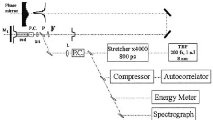
A schematic view of the experiment is shown in Fig. 1. The initial short pulse is generated by a diode-pumped laser [TB product (TBP)] that is mode-locked by a semiconductor saturable-absorber mirror. It generates 100-MHz short pulses with an 8-nm spectrum, 200-fs pulse duration, and an energy of 1 nJ. This pulse is stretched by a system of two gratings coupled to an afocal system to achieve 800-ps operation. The energy is amplif ied in a regenerative
Fig. 1. Schematic diagram of the CPA experiment: F, birefringent f ilter; P, polarizer; P.C., Pockels cell; L, lens. We show the chirped-pulse injection scheme and all the di-agnostics. The super-Gaussian circular mode is imaging just behind plane mirror M1. We measured the output
en-ergy, the cavity spectrum, and the pulse duration with the autocorrelator device.
August 1, 2003 / Vol. 28, No. 15 / OPTICS LETTERS 1375
amplifier. The amplifying medium is neodymium-doped phosphate glass (Hoya LHG8; 4 mm 3 4 mm 3 80 mm) side pumped with eight stacks of six diode bars (Thomson-CSF) that can deliver 2.9 kW of power for 400 ms. Because there is no cooling system, to limit the phase distortion that is due to main thermal loading we fixed the repetition rate at 1 Hz. The phase mirror is the main component of the cavity and permits the shaping of a circular super-Gaussian mode. The method of intracavity mode shaping consists of conjugating the diffracted field after propagation of a super-Gaussian circular mode on the phase mirror, which def ines the fundamental mode of the cavity.5
A phase mirror was selected instead of a phase plate to minimize intracavity loss. The initial mirror is concave, with a radius of 6 m. The phase mask is achieved by ion-beam etching.10
Figure 2 shows a prof ile of the dephasing of the mirror with the initial 6-m curvature of the mirror removed and a theoretical prof ile compared with the interferometrically measured actual mirror. The total measured phase is the sum of two measure-ments: a prof ilometer measurement for the center area and an interferometric measurement for global figuring. The peak-to-valley distance of the prof ile is⬃1 mm for a 30-mm diameter. We observed a good agreement between specifications and measurement, within 5% rms accuracy.
When this phase mirror is used, the fundamental mode of the regenerative cavity becomes super-Gaussian. The length of the cavity is optimized to maximize the diffraction losses of the next-higher mode of the cavity.1
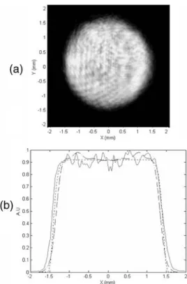
The optimal length of the cavity, which is approximately 4.9 m, depends essentially on the mode size and is close to the Rayleigh length of the beam. Figure 3(a) shows the intracavity fundamental mode. Its shape is circular and super-Gaussian. This mode prof ile was measured with an 8-bit CCD camera immediately after the plane mirror cavity. A comparison of the expected shape and the experi-mental measurement is made in Fig. 3(b). We have also plotted simulations of the mode shape produced by the cavity, including the measured phase of the mirror (Fig. 2). Both results are in good agreement with specif ications. A simulation of the phase mir-ror’s interferometric measurement yielded a 2.6-mm mode diameter with the 15th-order super-Gaussian, whereas the specif ication mode is 2.7-mm diameter with a 20th-order super-Gaussian. The direct mea-surement gave a 15th-order super-Gaussian mode with a diameter of 3.0 6 0.2 mm (FWHM), with 10% rms of modulation at the top of the beam.
The Findlay–Clay method was implemented to char-acterize losses and gain in the cavity.11
We measured the threshold current diode versus cavity losses in-duced by rotation of the intracavity quarter-wave plate. A plot of threshold current versus losses showed the losses and the amplif ication coefficient during one trip in the cavity. The experimental results yielded the value L 苷 12% for the single-pass losses. The expected linear relation between pump energy Ep and amplif ication coeff icient g0lis g0l苷 KEp, where
K 苷 0.5235 J21. The pump energy was 0.6 –1.3 J,
and the energy extracted without the spectral filter was 8– 80 mJ at 1 Hz. Figure 4 compares the ex-perimental results with theory. The exex-perimental results, which are in good agreement with regenerative cavity modeling,12
allow us to express the extracted energy (Eout) versus amplif ication coefficient (g0l) as
follows: Eout 苷 FsatS关g0l 2 L 2 L ln共g0l兾L兲兴, where Fsat is the saturation f luence, S is the beam mode
area, and L is the loss per round trip of the cavity. However, it is well known that a high regenerative cavity gain implies strong spectral gain narrowing. With an injected Lorentzian spectral bandwidth of 8 nm FWHM, the output spectrum is 1.2 nm (FWHM). To overcome spectral gain narrowing and to amplify a
Fig. 2. Phase prof iles of the phase mirror: specif ication (solid curve), interferometric measurement (dashed curve). The phase versus radius r is given without curvature (R苷 6m), and r苷 0 is the mode center.
Fig. 3. Experimental results: (a) circular mode measure-ment with the intracavity phase mirror, (b) experimeasure-mental result (solid curve), simulations with the phase mirror mea-surement (dashed curve), and specif ication (dotted curve).
1376 OPTICS LETTERS / Vol. 28, No. 15 / August 1, 2003
Fig. 4. Output cavity energy versus diode-pumped energy for a Q-switch cavity without a birefringent f ilter. The measurement points and the model curve given in Ref. 12 are shown.
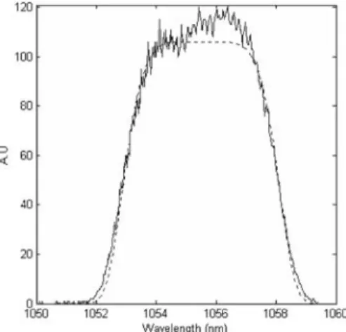
Fig. 5. Experimental spectrum: measurement (solid curve) and 6th-order super-Gaussian f itted curve (5.1 nm FWHM). This broadband spectrum was obtained with the intracavity birefringent plate.
Fig. 6. Autocorrelation signal measurement: experi-mental results (solid curve) and simulation obtained with the experimental spectrum (dashed curve).
broadband spectrum we inserted an intracavity bire-fringent f ilter. This f ilter permits a sinusoidal spec-tral amplitude shape to be generated.8
A 5-mm-thick
quartz plate near the Brewster angle was selected. Axial rotation allows us to control and to enlarge the pulse spectrum’s shape. Figure 5 shows the spectral prof ile after amplif ication, which has been fitted to a 6th-order super-Gaussian shape to yield 5.1 nm FWHM. An autocorrelation trace, tautoco 苷 700 fs,
was measured. From the spectral measurement it is possible to simulate the autocorrelator signal immediately after the grating compressor device. With the assumption of a Fourier-transform-limited pulse, a simple relation between the FWHM auto-correlation duration (tautoco) and the FWHM pulse
duration (tpulse) can be found. Our simulations gave
tpulse 苷 tautoco兾1.5. In Fig. 6 the autocorrelation
prof ile and the simulation prof ile are plotted. The good agreement between the simulations and the mea-surements shows that the spectral phase distortion is weak but that the high-order super-Gaussian spectral shape generates postpulses and prepulses. We found a pulse duration of tpulse 苷 470 fs with an output
energy greater than 20 mJ.
In conclusion, we have described extracted energy enhanced by a phase mirror, which yields a 15th-order circular super-Gaussian fundamental mode shape. We have shown that an intracavity spectral filter can overcome spectral gain narrowing. This scheme allows a chirped pulse to be amplif ied with a 5-nm output spectrum. Using a compressor device, we obtained a pulse duration of 470 fs with an energy of 20 mJ, leading to an output of 0.04 TW of power. For further advancement, this scheme could be en-hanced to the 100-mJ level by use of a cavity with only ref lective components to minimize intracavity losses.
We thank C. Le Blanc and C. Felix for helpful discus-sions of the amplif ication scheme. X. Ribeyre’s e-mail address is [email protected].
References
1. V. Bagnoud, J. Luce, L. Videau, and C. Rouyer, Opt. Lett. 26, 337 (2000).
2. D. Strikland and G. Mourou, Opt. Commun. 56, 219 (1985).
3. V. Kermene, A. Savoit, M. Vampouille, B. Colombeau, C. Froehly, and T. Dohnalik, Opt. Lett. 17, 859 (1992). 4. J. A. Hoffnagle and C. M. Jefferson, Optik (Stuttgart)
39, 5488 (2000).
5. R. Leger, D. Chen, and Z. Wang, Opt. Lett. 19, 108 (1994).
6. J. Bourderionnet, A. Brignon, J.-P. Huignard, A. Del-boulb, and B. Loiséaux, Opt. Lett. 26, 1958 (2001). 7. C. P. J. Barty, T. Guo, C. Le Blanc, F. Raksi, C.
Rose-Petruck, J. Squier, K. R. Wilson, V. V. Yakolev, and K. Yamakawa, Opt. Lett. 21, 668 (1996).
8. C. P. J. Barty, G. Korn, F. Raksi, C. Rose-Petruck, J. Squier, A.-C. Tien, K. R. Wilson, V. V. Yakolev, and K. Yamakawa, Opt. Lett. 21, 219 (1996).
9. J. Itatani, Y. Nabekawa, K. Kondo, and S. Watanabe, Opt. Commun. 134, 134 (1997).
10. R. Mercier, M. Mullot, M. Lamare, and G. Tissot, Rev. Sci. Instrum. 72, 1559 (2001).
11. D. Findlay and R. A. Clay, Opt. Lett. 20, 277 (1966). 12. W. Koechner, Solid State Laser Engineering, 3rd ed.