HAL Id: inria-00371397
https://hal.inria.fr/inria-00371397
Submitted on 27 Mar 2009
HAL is a multi-disciplinary open access
archive for the deposit and dissemination of
sci-entific research documents, whether they are
pub-lished or not. The documents may come from
teaching and research institutions in France or
abroad, or from public or private research centers.
L’archive ouverte pluridisciplinaire HAL, est
destinée au dépôt et à la diffusion de documents
scientifiques de niveau recherche, publiés ou non,
émanant des établissements d’enseignement et de
recherche français ou étrangers, des laboratoires
publics ou privés.
Analysis (and Simulation?)
Frédéric Mallet, Robert de Simone
To cite this version:
Frédéric Mallet, Robert de Simone. MARTE: A Profile for RT/E Systems Modeling, Analysis (and
Simulation?). First International Conference on Simulation Tools and Techniques for Communications,
Networks and Systems SIMUTools’08, ICST, Mar 2008, Marseille, France. pp.1-8. �inria-00371397�
MARTE: A Profile for RT/E Systems Modeling, Analysis
—and Simulation?
(invited paper)
Frédéric Mallet
AOSTE Inria/I3S project
Université de Nice Sophia Antipolis
INRIA / CNRS / UNSA
+33 4 92 38 79 66
[email protected]
Robert de Simone
AOSTE Inria/I3S project
INRIA Sophia Antipolis Méditerranée
INRIA / CNRS / UNSA
+33 4 92 38 79 41
[email protected]
ABSTRACT
As its name promises, the Unified Modeling Language (UML) provides a collection of diagrammatic modeling styles. To the early class/objects and use-case diagrams were almost immediately added state-, activity-, collaboration-, and component diagrams. All these modeling views, required for structural and behavioral representations of systems, were then progressed to further detailed expressivity. Provision for domain-specific specializations was made under the form of profiles. Somehow this goal of being rather universal and extendible discarded the possibility of UML to adopt too strict and precise a semantics; as users were generally to define and refine it in their stereotyped profiles anyway. As a result, even the little execution semantics there is in the standard is often not considered in such specializations.
We tackled the general issue of defining a broadly expressive Time Model as a sub-profile of the upcoming OMG Profile for Modeling and Analysis of Real-Time Embedded systems (MARTE), currently undergoing finalization at OMG. The goal is to provide a generic timed interpretation, on which timed models of computation and timed simulation semantics could be built inside the UML definition scope, instead of as part of the many external proprietary profiles. The MARTE time library can be used as the basis for the definition of a UML real-time simulator.
1. INTRODUCTION
Dictionaries define simulation as the act of (faithfully) imitating the appearance or character of something. In that sense, simulation tightly relates to modeling, and its accuracy is measured by the distance to the underlying models semantics. For complex systems, such models are to be shared by lots of people with different backgrounds (from project management and system level architects to designers and verification engineers). Then visual languages, such as the Unified Modeling Language (UML) [1], became increasingly popular for exchanging information between designers and distinct design phases, as its multiple diagrams provide modeling support to most aspects of systems, whether functional, behavioral or structural. Meanwhile, though, semantics was brought down to its minimal (light) consensual form: hardly enough to fully base a non-ambiguous (timed) simulation scheme.
Design practice is moving from traditional code-based
engineering, with a strong division of work along the
development life cycle, to model-driven engineering approaches where all people in the design flow can have their saying on the models. Aspect-oriented modeling allows for hiding irrelevant aspects of models depending on the considered point of view. Automated model transformations should be a ground for building tools that guarantee the semantics preservation between successive steps of the design flow. This trend is also happening in the domain of real-time and embedded (RT/E) systems, where traditional resource-constrained systems are becoming much more complex, not so constrained and involve more and more partners. UML is general-purpose and was designed to be customizable as a family of modeling languages. Its definition includes many
semantic variation points, that is to say areas in which multiple
interpretations of the specification are possible. The possible interpretations may be explicitly given or may remain implicit. This purposely loose semantics together with the UML refinement mechanism, called profiling, make UML a good base for building a domain specific modeling language without the prohibitive cost generally induced [2]. Indeed, main reasons that prevent a large adoption of domain-specific languages are the lack of adequate support (editors, compilers …) and the low availability of trained programmers. Using a UML profile offers a practical and cost-effective solution to reuse the large number of existing UML graphical frameworks and trained designers. This approach still requires a specialized training but with a reduced effort, though. Note that defining a UML profile to get a domain-specific modeling language is only possible when the domain-specific language is not in conflict with the UML semantics. Here again, the loose semantics of UML becomes an asset.
The relatively small community of the RT/E systems domain prevents major tool vendors from developing specific tools, making the domain an ideal candidate for defining a UML profile. In 2005, the UML Profile for Schedulability, Performance and Time (SPT) [3] was adopted by the Object Management Group (OMG) to provide UML with a quantifiable notion of time and resources and make it usable in the RT/E domain. Besides the fact that SPT was conformant with UML 1.4 and needed to be aligned with UML 2, several improvements were required. The OMG has issued a Request For Proposals (RFP) [4] to lead the path to a new specification that would supersede SPT. In 2007, the specification of the UML Profile for Modeling and Analysis of Real-Time and
Embedded (MARTE) [5] systems has been adopted and is currently undergoing finalization at OMG.
Our intention was to insist on time modeling, a fundamental aspects of models, almost absent in UML (mainly because of its numerous possible interpretations), and still that has to be a first-class modeling construct when addressing real-time systems. Giving a precise timed semantics to UML models makes it possible to feed them into performance analysis tools, whether analytical or simulation-based. MARTE, and the underlying UML tooling support, then provide a general framework to gather otherwise unrelated models. Using a consistent view of time brings the currently missing consistency amongst the UML models, even though these models cover different aspects of the system under design and possibly at different abstraction levels. Model-driven engineering gives the technology to build transformation models to link UML models and the real-time domain tools, fore and back, allowing interpretation in the UML world.
Section 2 briefly introduces UML and its extension mechanism. Section 3 gives an overview of MARTE. We try to give a description understandable by non UML specialists and we focus on aspects of interest for performance evaluation and simulation.
2. THE UML AND ITS PROFILES
A UML model consists of model elements such as classes, associations, activities, and state machines. Some elements can represent a functional decomposition (use cases), structural aspects (classes, composite structures, and components), behavioral aspects (state machines and activities), execution traces (collaborations, sequence) or physical deployments (nodes). UML diagrams are corresponding graphical representations of these model elements. UML diagrams contain graphical elements (nodes connected by paths) that represent elements in the UML model. The intended meaning of any model element can be refined by annotation called stereotypes. A profile is a complete domain-specific extension of UML with relevant stereotypes.
One of the most used UML diagram is the class diagram. After a brief description we show on to extend it with a dummy profile.
2.1 Class Diagrams
Representing classes is essential in object-oriented programming. In UML, classes own some properties (attributes/fields) and some operations (methods/functions). Figure 1 shows an example with the class PowerPC that owns one property (clockRate) and one operation (execute). The UML primitive type Natural represents the natural numbers and does not refer to a particular encoding (int, long).
Figure 1. Class and instance specifications
The two instance specifications (G3, G5) denote particular instances of the class PowerPC. The slot values are assumed to be expressed in MHz in this particular example. UML does not provide any effective mechanism to associate units with values. That is one of the MARTE contributions.
2.2 The UML Meta-Model
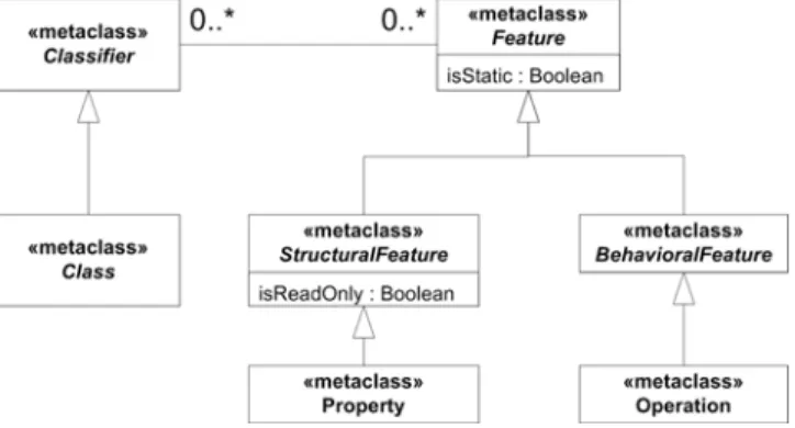
Even though UML is mainly a graphical language, still it requires a grammar so tool can automatically parse the models and check their syntax. For UML, the grammar is defined in the UML superstructure specification [1] using the Meta-Object Facilities (MOF). The MOF is another OMG specification and can be viewed as a minimal subset of UML. In UML the grammar is called a meta-model (or a level M2 model) and its basic elements are called meta-classes. Figure 2 shows a very small part of the UML grammar (meta-model) relative to the UML basic structural elements, the classifiers. The keyword «metaclass» differentiates a meta-class from a class.
Figure 2. Meta-model of a UML classifier
Reading the diagram, we see that each classifier can have an unbounded number of features (0..*). The features, which can be static or not, are further refined into structural features (like properties or signals) and behavioral features (like operations/methods). The line with the hollow triangle as an arrowhead represents a generalization. The arrowhead is directed from the more refined element towards the more general one. Generalization/Specialization and Inheritance are somehow different. Generalization is the concept, whereas inheritance is one of the ways offered by object-oriented languages to implement the UML generalization.
Note that the class diagram in Figure 1 is compliant with this classifier meta-model. The meta-model for instance specifications is not presented here.
UML-compliant tools must understand the whole UML meta-model. To extend UML there are two solutions. Either the designer defines new meta-classes or he defines extensions to the existing classes. The former approach is called meta-modeling and requires, at the very least, the modification of the modeling tools and could require the definition of a completely new tool. The latter approach is called profiling. A profile consists of several stereotypes that extend existing meta-classes, defining new constraints and giving a more precise semantics. Profiling is a much lighter approach and has already been implemented in several commercial UML tools whereas meta-modeling remains mainly a research domain.
2.3 A UML Profile
As an example of one possible extension to UML we might imagine that an architecture exploration tool needs to extract the processors contained in one particular system so to get the potential parallelism available. Unless the tool knows what a PowerPC is, and potentially all the names of all existing processors, it has no way to understand that the instances G3 and G5 are processors. A simple extension to UML would consist in tagging some model elements and explicitly identify them as processors. For instance, we could tag the class PowerPC. The definition of a UML profile consists in defining a set of stereotypes. Each concrete stereotype extends one or several existing meta-classes. Any model elements that conform to a given meta-class can be annotated with the defined stereotype as soon as the profile has been applied to the model.
Figure 3 (left-hand side) illustrates the definition of the stereotype Hw_Processor that extends the meta-class Class. Once the stereotype is defined, it can be applied to any class (Figure 3, right-hand side). In that way, an architecture exploration tool can easily tell the processors from any other model elements.
Figure 3. The stereotype Hw_Processor
2.4 Model libraries
Another interesting extension would be to assign a more explicit type to the property clockRate, a type that would represent a frequency. New types can be defined within model libraries. An element from a model library can be used at any level, in a meta-model, in a profile or in a normal UML model.
Figure 4. Example of a model library
Figure 4 shows a model library that defines a type Frequency. A frequency has a value (a real number) and a unit to be chosen amongst an enumeration of all possible units. Since UML does not have any type to represent real numbers, an easy way around consists in defining our own primitive type Real. Note that in spite of being in double brackets the keywords dataType, primitive
and enumeration are not stereotypes. This is only a graphical notation to distinguish classes from other structural elements.
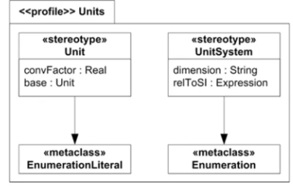
Figure 5. A profile for defining units
The enumeration FrequencyKind defines the set of possible units. To go further and establish relationships between the different units for the same dimension we can define (see Figure 5) a stereotype Unit that extends the meta-class EnumerationLiteral and a stereotype UnitSystem that extends the meta-class Enumeration. The stereotype Unit owns two properties (convFactor and base).
Figure 6. Identify units for the dimension frequency
Figure 6 applies the new stereotypes to the enumeration FrequencyKind and its literals. Values for the stereotype properties are provided within brackets. The conversion factors enable the evaluation of expression where several units are used for the same dimension. The stereotype UnitSystem explicitly identifies a dimension (e.g., frequency) and its relation to standard dimensions (e.g., frequency = 1/time). This provides for a mechanism to ensure dimension coherency within expressions.
2.5 What about simulation?
UML focuses very much on early design and modeling of systems and “simulability” is hardly an issue in UML literature. Some elements of operational semantics are provided for state, activity and sequence diagrams mostly, with for instance some attempts to define automatic transformations into Petri Nets ([6], [7], [8]). These approaches remain largely informal and subject to unspecified semantic variations. Anyway, most profiles come with semantic intentions that remain private to the stereotypes interpretation, and may defeat the little there is of UML semantics ([9], [10]).
In order to build proper (timed) simulation frameworks for UML models, we first need to introduce a time model and the possibility of adding clear time annotations to model elements. Second, we must provide subsets of the meta-model that correspond to analysis models as recognized in the simulation community.
We shall now introduce the MARTE profile which aims at providing such mechanisms in a well-defined and semantically grounded way.
3. MARTE
RT/E systems correctness critically depends on meeting one or more extra functional requirements, like real-time constraints, throughputs, and energy consumption or reliability criterions. The MARTE specification is made of three parts. The first part (MarteFoundations) lays the foundations to model such systems. The other two parts (MarteDesignModel and MarteAnalysisModel) elaborate on that base and specialize it to address respectively the design and the analysis aspects.
The first part defines the foundations for RT/E systems modeling and analysis. It supports the modeling of extra functional properties (see Section 3.1), including time properties (see Section 3.2), resources. It provides a generic execution platform model (see Section 0) as well as an allocation model (see Section 3.4) to allocate application model elements onto execution platform model elements.
The generic execution platform model is refined in the second part and differentiates software from hardware execution platforms. The third part concerns performance analysis and is described in Section 3.5.
3.1 Non-Functional Properties
MARTE non-functional properties (NFP) package comes with a user library (NFP_Types), a specification language called VSL (Value Specification Language) and stereotypes to help the definition of some domain-specific NFP. The package is very generic and there are some attempts to share it with other profiles coping with quality of service (QoS)-constrained systems. The library contains the main measurement units and dimensions from the international system of units. It provides support to build complex types, like matrices and vectors and some predefined NFP. For instance, the property ArrivalPattern specifies whether an event is periodic, a-periodic, sporadic, or its occurrence follows a given distribution.
Figure 7 shows an excerpt of the library NFP_Types to illustrate the definition of the type NFP_Duration. The enumeration DurationUnitKind is used as a dimension. The conversion factor allows for automatic computation of VSL expressions.
Figure 7. Excerpt of the library NFP_Types.
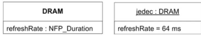
Figure 8 illustrates how the type can be used when defining a new type DRAM to model a dynamic memory and a particular instance of this memory with a refresh rate of 64 ms. The same expression can also be used as a constraint to specify that the system all with memories which refresh rate is less than 64 ms (see Figure 9).
Figure 8. Use of the type NFP_Duration
The analysis part heavily uses this package to define the UML model elements with which some NFP should be associated to apply a given schedulability (like Rate Monotonic Analysis— RMA) or performance (like queuing theory) analysis technique.
Figure 9. A VSL expression as an NFP constraint
3.2 The Time Model
In the domain of real-time and embedded systems, time has to be a first-class construct and not a mere annotation that comes after the functionality validation. Missing a deadline is often as faulty as not performing the right function. Though, apart from the various philosophical and theological discussions about time, and even restricting the scope to computer sciences, time can have various interpretations. Schreiber in [11] gives a time ontology for informatics.
However, UML, whose goal is to be very broad and platform-independent, is mainly untimed. The package SimpleTime of UML2 has a simplistic view of time and explicitly relies on specific profiles for dealing with complex aspects: “The simple
model of time described here is intended as an approximation for situations where the more complex aspects of time and time measurement can safely be ignored. … It is assumed that applications for which such characteristics are relevant will use a more sophisticated model of time provided by an appropriate profile.” (UML Superstructure v2.1.2, p. 423).
Duration, observation and time measurement constructs introduced by SPT were conflicting with the package SimpleTime. Some key concepts were missing to tackle relativistic effects that may appear in distributed systems or issues induced by systems with multiple clock domains (like many-core architectures or network-on-chip). Thus, MARTE chapter Time gives a rich theory, inspired from the tagged signal model [12], to model time-related aspects appearing when dealing with RTE systems. In MARTE, Time can be physical, and considered as continuous or discretized, but it can also be logical, and related to user-defined clocks. Time may even be multiform, allowing different times to progress in a non-uniform fashion, and possibly independently to any (direct) reference to physical time. The time
structure is defined by a set of clocks and relations on these
clocks. Here clock is not a device used to measure the progress of physical time. It is a mathematical object lending itself to formal processing instead. A clock that refers to physical time is called a
chronometric clock. A distinguished chronometric clock called
idealClk is provided in the MARTE time library. This clock represents the “ideal” physical time used, for instance, in physical and mechanics laws. At the design level most of the clocks are logical ones.
Instances of logical “non-ideal” clocks are: the execution cycles of a processor (e.g., in a world where processor clock rate can be adapted for power saving); the sequence of instructions of a thread (in a time sharing system where some an operating system allocates execution cycles amongst several such threads); algorithmic steps (in an abstract setting where data memory is not mapped); an engine rotation angle (when action has to be taken each 90° angle for instance). A general theory of multiform time and “scheduling-as-time harmonization” has been developed [12] and is a main influence in MARTE time model.
More precisely, a clock is an ordered set of instants with a labeling function and a unit symbol. For chronometric clocks, the unit can be the SI time unit s (second) or one of its derived units (ms, s, ns …). For logical clocks, the usual unit is tick, but clockCycle, executionStep may be chosen instead.
Clocks are a priori independent. They become dependent when their instants are linked by instant relations imposing either coincidence between instants or precedence. Clock relations are a convenient way to impose many—often infinitely many—instant relations. A time structure is set of clocks and instant relations. A time structure is then a partially ordered set of instants.
During a design we introduce several (logical) clocks that are progressively constrained. This strengthens the ordering relation of the application time structure. The time structure can be used by timing analysis tools to decide whether the requirements are met. It can also be used by a simulator to execute the model. When the ordering relation is total, there is one unique execution and the simulation is deterministic. Otherwise, one possible execution scenario can be chosen (deterministically or not) among all possible ones.
A support for multi-clock systems is required in GALS (Globally Asynchronous, Locally Synchronous) approaches and also in distributed real-time systems subject to relativistic observation effects. In that context, being distributed does not necessarily involve a large scale network but rather an embedded one (like CAN, TTP or FlexRay) often used in automotive or avionics applications. Even system-on-chips have the same kind of problems, mostly with many-core architectures and network-on-chip, but also with mono-core high integration architectures where the end-to-end latencies across the chip are not negligible any more.
Another very important trait introduced by MARTE and that was ignored by UML is the ability to deal with multiform time. This feature allows for using several quantities (not only time) to express deadline requirements or constraints. We can obviously use durations (1.5 ms) or dates (before tomorrow noon), but also rates (25 times per second) or expressions relative to any event occurring in the system (before the camshaft has performed a rotation of 90°).
We have tried to introduce all these concepts while defining new stereotypes with parsimony. Figure 10 illustrates the definition of a timed state machine where event occurrences depend on the rotation angle of a car camshaft. The example used is a model of a four-stroke engine cycle. Applying the stereotype TimeProcessing associates the clock camClk with a UML behavior (a state machine, an activity or an interaction). The default unit for this clock is °CAM. Some clock relations can be established between
the camshaft rotation, the engine rotation speed and the clock cycles of the injection controller.
Figure 10. A state machine with multiform time
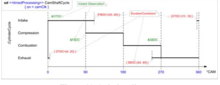
Another very useful UML construct to represent timing information is the timing diagram. Timing diagrams can be used either to represent a single execution trace, like a waveform, but they can also represent a family of possible traces.
Figure 11. A timing diagram
Figure 11 shows a refinement of the internal combustion engine cycle that highlights the overlapping of the engine strokes. The time observations (in green) identify significant events in the system (OTDC – Overlap Top Dead Center, FBDC – First Bottom Dead Center, SBDC – Second Bottom Dead Center). The time constraints (in red) specify deadline requirements. For instance, the intake stroke must complete during a precise time range ([40..60]) after the beginning of the compression stroke (FBDC). The time range is expressed in degrees and refers to the rotation of the camshaft (°CAM). The physical time slot varies according to the engine rotation speed. These timing constraints can be used by a simulation engine to insert automatic probes (observers) and anticipate incorrect behaviors.
3.3 The Execution Platform Model
When the application has been functionally specified and the expected QoS have been defined, the actual cost of the execution platform must be taken into account. Choosing the right execution platform is often a problem, several solutions are available. The easiest approach consists in using a general-purpose processor and generating the code for it from the specification. Unfortunately, this solution is often too slow for high performance applications. The highest performances are generally achieved when using a fully customized hardware accelerator (ASIC – Application Specific Integrated Circuit) but this approach is very expensive and time consuming. Some intermediate solutions are also possible. In any case, a trade-off between the cost and the performances must be found, this difficult process is called architecture exploration or hardware/software partitioning. Often, to abstract away the application from the actual hardware execution platform, an intermediate layer is added, a middleware.
Even though MARTE does not bring any solution, it supports the modeling of the execution platforms either software (middleware, operating systems, and virtual machines) or hardware. It also supports the modeling of all the possible solutions and the final decision. Whatever the level of these execution platforms, they share some commonalities. The package GenericResourceModel (GRM) provides generic stereotypes to describe these commonalities. It differentiates the computing resources from the communication resources. It also separates active processing resources from passive storage resources. All resources may provide or require some services.
In the second part of MARTE, the package GRM is specialized by the package DetailedResourceModel (DRM) that itself splits into two sub-packages SoftwareResourceModel (SRM) and HardwareResourceModel (HRM).
The package SRM concerns real-time operating systems or virtual machines. MARTE annexes contain some guidelines to model ARINC653, POSIX or OSEK. The abstract computing resources of GRM are refined into threads or tasks. The passive resources can for instance be mutual exclusion resources like POSIX mutex or semaphores.
The package HRM provides stereotypes to model, at different abstraction levels, processors, memory hierarchies, ASIC, programmable logic devices (PLD).
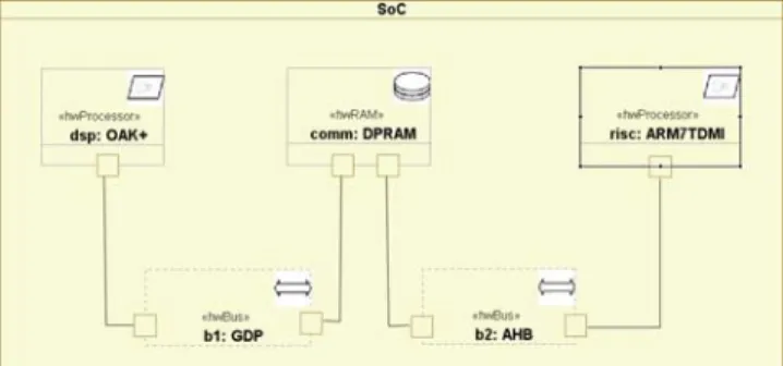
Figure 12 illustrates the use of the package HRM with a UML composite structure diagram. The example is a bi-core system-on-chip (SoC) made of a digital signal processing (DSP) processor and a general-purpose RISC (Reduced Instruction-Set Computer) processor. The DSP processes data-intensive part of the application whereas the RISC processes its control part (when different algorithms must be executed and how do they relate to each other). The two cores communicate through a double port memory (DPRAM). On one side of the communication, the AMBA High performance Bus (AHB) is used and on the other side a general data bus (GDP) is used. Some properties are associated with the stereotypes. For instance, the stereotype «hwProcessor», comes with properties to specify its frequency (the type NFP_Frequency has been defined for this purpose in the library NFP_Types), the size of its internal memory (the type is NFP_DataSize), the length of its pipeline …
With that capability, UML can be used as an architecture description language on top of the behavioral description. Choosing a two-layer approach provides a great flexibility for hiding irrelevant details of the behavior thus enabling the interoperability of multi-level models. This is happening with OCSI SystemC and the SPIRIT consortium XACT format. IP-XACT is a language-independent front-end that allows for the specification of Intellectual Property (IP) meta-data and tool interfaces. It uses its own XML syntax to describe structure. For behavioral representation, IP-XACT relies on SystemC, VHDL, and Verilog HDL to specify the actual behavior of components. SystemC provides programming libraries to represent IP component behavior at different abstraction levels, from Transaction Level Modeling (TLM) to RTL but it requires additional support for architecture modeling.
Figure 12. Modeling a hardware execution platform
3.4 The Allocation Model
When models of the application and the possible execution platforms are performed, the architecture exploration relies on the possible mappings of the former onto the latter to decide what solutions meet the requirements. In case there are several possible solutions, the designer must choose the most cost-effective one. In MARTE these mappings are called allocation. Allocations comprise both spatial distribution and temporal scheduling aspects, in order to map various algorithmic operations onto available computing and communication resources and services. The temporal scheduling is required when several application elements are allocated to the same execution platform model element (same processor or same thread) or when synchronizations are required between different elements (e.g., two threads).
Both application and execution platform elements have structural and behavioral aspects. The allocation often requires prior adjustment (inside each separated model) to abstract/refine its components and allow a direct match. Allocation can be viewed as a “horizontal” association, and abstraction/refinement layering as a “vertical” one, with the abstract version relying on constructs introduced in the refined model. Even though different in role, allocation and refinement share a lot of formal aspects, and so both are described in the same chapter.
Application and Execution platform elements can be annotated with NFP information. Allocation and refinement provide relations (UML constraints) between these properties. Properties such as time or space requirement, cost, or power consumption are also considered.
In MARTE, we use the word allocation rather than deployment (as in UML) since deployment implies a physical distribution whereas allocation can also be logical (scheduling). For instance, two pieces of an algorithm could be allocated to two different processor cores, while the executable file containing both pieces would be deployed on the memory of the processor and the source file containing the specification of the algorithm would be deployed on a hard disk. This dual function was recognized in SPT, where allocation was called realization, while refinement was used as such. MARTE allocation and refinement are complementary to the UML deployment; we prefer to keep the three concepts separated. This is not the case of other modeling languages (like AADL) that, most of the time, merge them. The allocation mechanism proposed by MARTE is inspired by the SysML ([13]) allocation. However, MARTE makes it explicit that both the logical and physical parts could be either of a behavioral or structural nature. Contrary to SysML where any element can be
allocated onto any other element, MARTE only allows the allocation of application elements onto execution platform elements. Another difference is that MARTE explicitly separates allocation from refinement.
Figure 13 shows an example of allocation. The application is described as a UML activity diagram with two swim lanes that model the potential allocation of each action. Note that the intersection between the two swim lanes is not empty. The action oper2 can be executed on any of the two processors. However, the cost may not be the same. Typically a DSP processor can execute a multiply-accumulate operation in one cycle whereas it would take many more cycles with a RISC. It is also important to note that the communications cannot be neglected. That is where it becomes critical to get an accurate description of the platform (see Figure 12).
Figure 13. An example of allocation
There are different ways to represent the cost of the allocations. A very practical way is to use a table. Tables are officially mentioned as acceptable UML models but unfortunately very few tools actually support this notation. The tables below (Figure 14) illustrate a possible graphical representation. There are no units here because such tables can be supplied for any relevant QoS. The column Unique Alloc identifies whether or not the duplications of particular actions are allowed. When the duplications are allowed, time performances may be better but the implementation cost is generally higher.
Figure 14. Allocation cost
A more detailed description of MARTE allocation model is available in [14].
3.5 MARTE Analysis Model
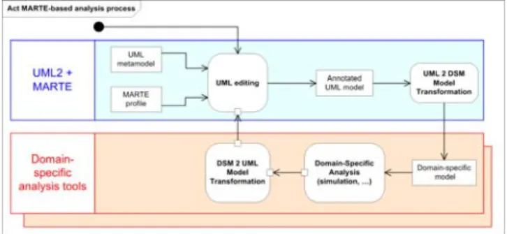
MARTE analysis model does not introduce or target new specific analysis techniques. Rather it aims at representing well-known models from schedulability and performance analysis theories into a UML framework [15]. Following a model-driven engineering process, transformation tools should be able to extract the relevant information from MARTE models, feed them into appropriate tools and bring the results back into UML for interpretation or as back annotations to refine the models and iterate with other tools (Figure 15).
The profile SPT was already offering constructs to support quantitative analysis. However, the schedulability and performance analysis packages in SPT were totally independent. In MARTE, in addition to an alignment with UML2, the two
packages have been unified and both rely now on the same foundations. New stereotypes have been introduced to model, amongst others, jitter, transmission delays, deadline miss rates, execution time (worst-case, best-case and average), and many others.
Figure 15. Performance analysis with MARTE
Thus MARTE provides a common basis for both schedulability analysis (Rate Monotonic, Deadline Monotonic, holistic approaches) and performance analysis (queue networks, Petri nets, stochastic process algebra). This basis can be adapted to other quantitative analysis techniques via the definition of model libraries.
4. CONCLUSION
One main issue in simulation-based techniques is to understand the exact relation between what is simulated (usually a mathematically grounded model), and what is implemented or run (usually a software/hardware-based system). The same observation would be true for high-level modeling frameworks such as UML with respect to their implementation. It is certainly inevitable that connections between man-made models and the physical, more concrete, reality they are meant to represent (itself of natural or human source), would remain informal and assumed by faith. But if the same model contains the whole information (in our case mainly concerning timing and other extra functional requirements) from the design to the implementation through analysis and testing, then there is of course a better chance that they would coincide in the end.
In that direction, we provided a generic and broad sub-profile for Time Modeling, as part of the UML profile for MARTE, so that sophisticated timing relations can be expressed in UML models and identically understood by other (private) profiles using it. As a result, this can be thought of as a foundational step, defining a timed dynamic semantics of UML models and naturally leading to the possibility of timed analysis (schedulability and performance) and timed simulation, while there is nothing of this kind currently existing at all. However, there is still a long way before user-friendly analysis models can be represented. This would require a library of useful simulation patterns to ease the designer task.
5. ACKNOWLEDGMENTS
The original document is available in the ACM Digital Library (http://portal.acm.org/citation.cfm?id=1416222.1416271). MARTE is the result of the work of an international consortium
(http://www.omgmarte.org) that gathers tool vendors, industrial
Some of the work presented here was funded by the CAROLL initiative, a joint partnership between CEA, INRIA and Thales. Some examples used to illustrate this article have been implemented in Papyrus UML, an open-source graphical UML editor available at http://www.papyrusuml.org.
6. REFERENCES
[1] The Object Management Group. 2005. The Unified Modeling Language (UML). OMG Adopted Specification v2.1.2. http://www.omg.org/spec/UML/2.1.2/.
[2] B. Selic. 2007. A Systematic Approach to Domain-Specific Language Design Using UML. In Proceedings of the 10th IEEE International Symposium on Object and Component-Oriented Real-Time Distributed Computing (Santorini Island, Greece, May 07 - 09 2007). ISORC’07. IEEE Computer Society, 2-9.
[3] The Object Management Group. 2005. The UML Profile for Schedulability, Performance and Time (SPT). OMG Adopted Specification v1.1. Document Number: formal/05-01-02. http://www.omg.org/cgi-bin/doc?formal/2005-01-02.
[4] The Object Management Group. 2005. UML Profile for Modeling and Analysis of Real-Time and Embedded systems. OMG Request For Proposals, realtime/05-02-06. http://www.omg.org/cgi-bin/doc?realtime/05-02-06.pdf. [5] The Object Management Group. 2005. The UML Profile for
Modeling and Analysis of Real-Time and Embedded systems, beta 1. OMG Adopted Specification, ptc/07-08-04. http://www.omg.org/cgi-bin/doc?ptc/2007-08-04.
[6] H. Störrle. 2005. Semantics and Verification of Data Flow in UML 2.0 Activities. Electronic notes in Theoretical Computer Science, 127(4), pp. 35-52.
[7] J.P. Lopez-Grao, J. Merseguer, and J. Campos. 2004. From UML Activity Diagrams To Stochastic Petri Nets. Proc. Int. Workshop on Software and Performance, January 2004, Redwood City, CA, USA, pp. 25-36.
[8] F. Mallet, M-A. Peraldi, C. André. 2006. From UML to Petri Nets for non functional Property Verification. In Proc. of the IEEE Int. Symposium on Industrial Embedded Systems (IES'2006), October 2006, France. ISBN: 0-7803-9759-2. [9] The Object Management Group. 2006. Semantics of a
Foundational Subset for Executable UML Models. Initial Submission. Document Number: 06-05-02.
http://www.omg.org/cgi-bin/doc?ad/06-05-02.pdf.
[10] C. Hardebolle and F. Boulanger. 2007. ModHel'X: A Component-Oriented Approach to Multi-Formalism Modeling. Proc. of the 4th Workshop on Multi-Paradigm Modeling (MPM'07) at MoDELS, BME-DAAI Technical Report Series, 1: pp. 49-60. October 2007.
[11] F.A. Schreiber. 1994. Is time a real time? An overview of time ontology in informatics. Real-Time Computing. F127:283-307, 1994.
[12] E.A. Lee and A. Sangiovanni-Vincentelli. 1998. A framework for comparing models of computation. IEEE Transactions on CAD of Integrated Circuits and Systems (TCAD) 17(12):1217-1229.
[13] The Object Management Group. 2007. Systems Modeling Language (OMG SysML) v1.0. OMG Available Specification. Document number: formal/2007-09-01. http://www.omg.org/cgi-bin/doc?formal/2007-09-01.
[14] C. André, F. Mallet, and R. de Simone. 2007. Modeling Time(s). In Proceedings of the ACM/IEEE International Conference on Model Driven Engineering Languages and Systems (MoDELS/UML), October 2007, TN, USA. Springer Verlag, LNCS 4735, pp. 559-573.
[15] M. Woodside. 2007. From Annotated Software Designs (UML SPT/MARTE) to Model Formalisms. Formal Methods for Performance Evaluation, 7th Int. School on Formal Methods (SFM’07) for the Design of Computer, Communication, andd Software Systems, SFM 2007, Bertinoro, Italy, May 28-June 2. LNCS 4486, Springer.