Publisher’s version / Version de l'éditeur:
HVAC and R Journal, 19, 1, pp. 63-75, 2012-11-27
READ THESE TERMS AND CONDITIONS CAREFULLY BEFORE USING THIS WEBSITE. https://nrc-publications.canada.ca/eng/copyright
Vous avez des questions? Nous pouvons vous aider. Pour communiquer directement avec un auteur, consultez la
première page de la revue dans laquelle son article a été publié afin de trouver ses coordonnées. Si vous n’arrivez pas à les repérer, communiquez avec nous à PublicationsArchive-ArchivesPublications@nrc-cnrc.gc.ca.
Questions? Contact the NRC Publications Archive team at
PublicationsArchive-ArchivesPublications@nrc-cnrc.gc.ca. If you wish to email the authors directly, please see the first page of the publication for their contact information.
NRC Publications Archive
Archives des publications du CNRC
This publication could be one of several versions: author’s original, accepted manuscript or the publisher’s version. / La version de cette publication peut être l’une des suivantes : la version prépublication de l’auteur, la version acceptée du manuscrit ou la version de l’éditeur.
For the publisher’s version, please access the DOI link below./ Pour consulter la version de l’éditeur, utilisez le lien DOI ci-dessous.
https://doi.org/10.1080/10789669.2012.736812
Access and use of this website and the material on it are subject to the Terms and Conditions set forth at
Optical model for prismatic glazing (1415-RP)
Laouadi, Abdelaziz; Saber, Hamed H.; Galasiu, Anca D.; Arsenault, Chantal
https://publications-cnrc.canada.ca/fra/droits
L’accès à ce site Web et l’utilisation de son contenu sont assujettis aux conditions présentées dans le site LISEZ CES CONDITIONS ATTENTIVEMENT AVANT D’UTILISER CE SITE WEB.
NRC Publications Record / Notice d'Archives des publications de CNRC:
https://nrc-publications.canada.ca/eng/view/object/?id=1ca732a8-28c0-450d-8f6c-9ed5ef1373d5 https://publications-cnrc.canada.ca/fra/voir/objet/?id=1ca732a8-28c0-450d-8f6c-9ed5ef1373d5
Optical Model for Prismatic Glazing
(1415-RP)
Abdelaziz Laouadi
*, Hamed H. Saber, Anca D. Galasiu, Chantal Arsenault
NRC Construction PortfolioNational Research Council Canada
1200 Montreal Road, Ottawa Ontario, K1A 0R6, Canada Tel: (613) 990 6868. Fax: (613) 954 3733
* Corresponding author. Email: aziz.laouadi@nrc-cnrc.gc.ca
Abstract
Prismatic glazing is found in many building applications such as complex fenestration systems to control solar heat gains and glare, and re-direct sunlight to building interior spaces, and daylighting (and lighting) systems to enhance their optical and lighting performance. However, modelling and simulation of such prismatic glazing has been a very difficult task due to its versatile and complex geometrics. This paper presents the development and validation of a simplified model to compute the optical characteristics and dominant directions of the transmitted and reflected beam rays of saw-tooth like prismatic glazing. The model was based on tracing the average ray, and was extensively validated using third-party data derived from ray tracing computer simulations, and measurement using integrating spheres and goniophotometers. The model’s predictions for the transmittance and reflectance of single and double prismatic panes compared overall well within the accuracy of the third-party data over all incidence angles.
Introduction
Prismatic glazing consists of arrays of micro or macro-replicated shapes which may reflect, refract and redirect incoming light to suit a particular application. The underlying features of prismatic glazing lay in the total internal reflection, angular re-direction of incident light, and light scattering. Those features have been widely exploited in many building applications. In complex fenestration systems such as windows, skylights, and solar shading devices, prismatic glazing is used to control solar heat gains and glare (e.g., reflective and angular-selective glazing) and re-direct sunlight to ceiling surfaces of building interior spaces (Wirth et al.,1998; Lorenz, 2000; Walze et al., 2005; Hocheng et al, 2010; Hocheng et al, 2011; Klammt et al., 2012). In daylighting systems such as tubular daylighting devices (Solatube, 2012; ODL, 2012; Skydome, 2012), sunlighting systems (Laouadi, 2011; Laouadi and Coffey, 2012), and light guides (Whitehead et al.,1982; Saxe, 1989; 3M, 2000), prismatic structures are used to enhance the system optical performance (light transmission, and diffusion) and to transport sunlight into deep spaces of building floors. In lighting systems, prismatic structures are used in light diffusers to enhance transmission efficiency and quality of light diffusion. In solar energy systems such as photovoltaics and solar collectors, prismatic structures are used as light trapping and concentration devices to increase system efficiency (Gombert et al, 2004a; Slaman and Griessen, 2009; Blasi et al, 2010; Chen et al., 2010). However, despite these widespread applications, modelling and simulation of prismatic glazing has been a very difficult task due to its versatile and complex geometrics.
There are various shapes of prismatic structures molded on thin film or thick glazing substrates. Saw-tooth like prismatic structures is one of the popular shapes. Due to their complex geometry and its interaction with electromagnetic waves, advanced optical modelling and detailed measurement techniques have been used to characterise their optical performance. Critten (1988) developed a very simple model, ignoring medium absorption, to compute light transmission and distribution of right-angle macroscopic prismatic glazing. The aim of the study was to optimize the light distribution through the glazing of an east-west aligned greenhouse situated at high latitude by redirecting the light to the northern and southern areas of the greenhouse based on the seasonal changes in the sun path. Wirth et al. (1998) used commercial ray tracing software to compute the angular profiles of transmittance for right-angle single and double
prismatic glazing used in solar shading devices. Ouellette et al. (1992) used the Monte Carlo ray tracing technique to compute the reflectance of single and double stack of right-angle prismatic films. Gombert et al. (2004b) used specialized optical computer codes based on the diffraction theory of electromagnetic waves to compute the transmittance of microscopic prismatic reflectors for solar shading devices. Andersen at al. (2003), Andersen (2004), and Andersen (2006) developed a new video goniophotometer to measure the bidirectional transmission distribution functions of right-angle and asymmetric prismatic glazing and films. Ray tracing simulations using commercial software were also performed for comparison with the measurement results. Good agreement between the two approaches was found. The goniophotometer results for the hemispherical transmittance were also compared with third-party measurement results using integrating spheres. Both measurement results compared well within the measurement uncertainty.
Objectives
The present study is a part of an ASHRAE research project (1415-RP) to evaluate the optical and thermal performance of tubular daylighting devices. The aim of this paper is to develop a simplified model to compute the optical characteristics of prismatic glazing with quick calculation time so that the model can be integrated in existing fenestration computer design tools. The specific objectives are:
To develop an analytical algorithm to compute the optical characteristics (transmittance, reflectance and absorptance) of two-dimensional, saw-tooth like prismatic panes at oblique incidence angles.
To validate the model using third-party measurement and detailed ray tracing computer simulations.
Mathematical Formulation
Consider a saw-tooth like prismatic pane as shown in Figure 1. The prism is characterized by its slope angle (), draft angle (), and height (h). The pane total thickness is noted as (d). Right angle prisms ( == /4) are the most popular in daylighting and lighting applications. Right angle prismatic panes may act as an angularly-selective glazing, totally reflecting incident radiation within certain acceptance angles and highly transmitting in the remaining angles. Other prism shapes are also used to significantly change the direction of the transmitted rays from the incidence direction to concentrate or diffuse beam light.
Transmission, reflection and absorption of incident radiation are dependent on the prism orientation with respect to the direction of the incident radiation, and position of prism gratings on the pane surface. To derive general formulations, consider a coordinate system (x, y, z) whose x-axis is parallel to the prism longitudinal axis (groove direction), and the z-axis is normal to the pane surface. The x-axis of the prism is oriented in such a way that the sloped facet faces the positive direction of the y-axis (the draft facet faces the negative direction of the y-axis). The prism x-axis may be oriented to make an angle (xp, positive
counter-clockwise) with respect to the x-axis of a reference coordinate system attached to the pane surface. In the following, an approximate model will be developed to compute the optical characteristics of a prismatic pane based on the ray tracing technique applied to the mean (average) radiation path. Although the prediction of the optical characteristics of prismatic panes is a complex task due to the complex geometry, the aim of the approximate model is to sufficiently predict the total transmittance and reflectance and the dominant directions of the transmitted and reflected rays to facilitate their ray tracing in other glazing panes making up a fenestration system. Dispersion of the incident rays in directions other than the dominant directions is treated diffuse in the model despite its importance in lighting calculation. The following assumptions are used:
d h y z xref x xp
Slopped facet Draft facet
Figure 1 Cross-section of a prismatic pane
ASSUMPTIONS
Prism pitch (groove spacing) is larger than the wavelength of incident radiation so that radiation diffraction/scattering at the prism facets is neglected (Blasi et al., 2009);
Only the first reflection and transmission cycles at the prism facets are traced. Subsequent internal reflection cycles are assumed to follow the same path as in the first reflection cycle.
FRONT OPTICAL CHARACTERISTICS
Figure 2 shows the path of an average ray incident on the pane surface when the prism is placed at the back surface of the glazing pane. The incident rays make an azimuth angle (i) with respect to the prism
x-axis, and a polar angle (z,i) from the z-axis. Incident rays may reach both the sloped or draft facet, and
may undergo multiple upward or downward reflections between the two facets before exiting from the front or back pane surface. Up to two upward reflections are traced in the model (as shown in the figure 2), but only one reflection is accounted for in the downward reflections. Subject to the foregoing assumptions, the front reflectance and transmittance of a prismatic pane are expressed as follows:
(1) (2) where:
F : averaging factor (to be determined);
f,s: front reflectance of pane for an average ray reaching the sloped facet of the prism;
f,d: front reflectance of pane for an average ray reaching the draft facet of the prism;
f,s : front transmittance of pane for an average ray reaching the sloped facet of the prism;
q00 (1-1) q0 0 11(1-2) 0 qi = 1 p0 p1 p2
x
y
z
z,i
i p3 p4 q1 q0 0 1122(1-3) q0 0 112233 (1-4)Figure 2 Path of an average ray incident on one of the prism facets when the prism is placed on the back pane surface
Equations (1) and (2) are evaluated by tracing an average ray for each prism facet. The averaging factor (F) is determined based on the area proportion of the average refracted ray at point (p0) reaching the
prism facets:
(3) where (t.p0) is the profile angle of the refracted ray at point p0, expressed as follows:
(4) where:
z,t,i,p0: polar angle from the negative z-axis of a refracted ray at point p0and incident on the slopped
prism facet, Equation (42), (radians);
t,i,p0 : azimuth angle from the x-axis of a refracted ray at point p0and incident on the sloped prism
The average dominant directional angles of rays transmitting through or reflecting off the prismatic pane are set equal to the directional angles of rays incident on the sloped facet if the product (F f,s) is higher than the product ((1-F) f,d). Otherwise, the average dominant directional angles are
equal to those when rays are incident on the draft facet.
The front reflectance and transmittance for an average ray reaching the first prism facet are expressed as follows:
(5) (6) where:
q0 : interface radiation flux at point p0per unit incident radiation flux;
q1 : interface radiation flux at point p4per unit incident radiation flux for the first inter-reflection
cycle;
qj : interface radiation flux at point p4per unit incident radiation flux for the jth inter-reflection cycle;
f,1: front reflectance of pane for an average ray reaching the first prism facet (either the sloped or
draft facet);
0 : interface reflectivity at point p0;
1 : interface reflectivity at point p1;
2 : interface reflectivity at point p2;
3 : interface reflectivity at point p3;
f,1: front transmitance of pane for an average ray reaching the first prism facet (either the sloped or
draft facet);
0 : transmissivity between points p0 and p1;
1 : transmissivity between points p1 and p2;
2 : transmissivity between points p2 and p3;
3 : transmissivity between points p3 and p4.
The interface radiation fluxes (qj) are expressed recursively as follows:
(7) Substituting Equation (7) in Equations (5) and (6), one obtains:
(8) (9)
Equations (8) and (9) may also be applied to the second prism facet, by replacing the index (1) with (2).
It should be noted that Equations (8) and (9) are developed when the average incident ray undergoes two upward reflections off the first prism facet (points p1and p3), and one reflection off the second facet at
point p2. If the average ray reflecting upward off the first facet at point p1 does not reach the second facet
at point p2, the interface reflectivity and transmisivity at points p2and p3 are set equal to 2= 3= 2= 3= 1
in Equations (8) and (9). The average upward reflected ray at point p1does not hit the second prism facet at
point p2if the profile angle of the reflected ray incident on the second facet is lower than a threshold value,
expressed as follows:
(10) where:
2 : polar angle from the z-axis of the normal of the internal surface of the second prism facet at point
p2(radians);
z,r,i,p1: polar angle from the z-axis of the average ray reflected off the first prism facet at point p1and
incident on the second prism facet at point p2, Equation (36), (radians);
r,i,p1 : azimuth angle from the x-axis of the average ray reflected off the first prism facet at point p1
and incident on the second prism facet at point p2, Equation (36), (radians);
p2: azimuth angle from the x-axis of the normal of the internal surface of the second prism facet at
point p2(radians);
r,p1 : profile angle from the z-axis of the average ray reflected off the first prism facet at point p1
(radians).
Similarly, if the average ray reflecting upwards off the second facet at point p2 does not reach the first
facet at point p3, the interface reflectivity and transmisivity at point p3 are set equal to 3 = 3 = 1 in
Equations (8) and (9). The average upward reflected ray at point p2does not reach the opposite prism facet
at point p3if the profile angle of the reflected ray at point p2is lower than a threshold value, expressed as
follows:
(11) where:
1 : polar angle from the z-axis of the normal of the internal surface of the first prism facet at point p1
(radians);
z,r,i,p2: polar angle from the z-axis of the average ray reflected off the second prism facet at point p2,
r,i,p2 : azimuth angle from the x-axis of the average ray reflected off the second prism facet at point p2
and incident on the opposite prism facet at point p3, Equation (37), (radians);
p1: azimuth angle from the x-axis of the normal of the internal surface of the first prism facet at point
p1(radians);
r,p2 : profile angle from the z-axis of the average ray reflected off the second prism facet at point p2
(radians).
The average ray is reflected upwards off the prism facet at point p3if its polar angle z,r,p3 > /2.
Otherwise, the average ray reflected at point p3is channelled downwards. In the latter case, the interface
reflectivity at point p3is set to zero in Equations (8) and (9).
The interface reflectivity and transmissivity in Equations (8) and (9) are calculated using the Fresnel laws of optics (Siegel and Howell, 2002). For a polarized radiation, the interface reflectivity is expressed as follows:
(12) where:
i : angle of incidence from the surface normal (radians);
t : angle of refraction from the surface normal (radians);
: interface reflectivity for the parallel component of polarized radiation;
: interface reflectivity for the perpendicular component of polarized radiation.
The angle of incidence is related to the angle of refraction using the Snell’s law:
(13) where niand ntare the index of refraction of the incidence, and refraction medium, respectively.
The transmissivity of a medium (m) indicates the attenuation of the radiation intensity in the medium
(denoted by m). It is expressed as follows:
(14) where kmis the attenuation coefficient of medium (m-1, ft-1), tmthe thickness of medium (m, ft), and the
Equations (13) and (14) are applied to each interface at the points (p0, p1, p2, p3, p4) of Figure 2. The
average thickness of the media between p0and p1, p1and p2, p2and p3, and p3and p4 are given by the
following relation:
(15) If the reflected rays at point (p1) do not reach the opposite prism facet at point (p2), the thickness of the
medium between the points p1and p3is t1= t0. Similarly, if the reflected rays at point (p2) do not reach the
opposite prism facet at point (p3), the thickness of the medium between the points p2and p4is t2= t0.
The directional angles (polar angle from the z-axis, and azimuth angle from the x-axis) of the reflected and refracted rays at the interface points (p0, p1, p2, p3, p4) are calculated using the formula developed in the
Appendix (Equations (32) to (35) for reflection, and Equations (38) to (41) for refraction) by substituting the tilt and azimuth angles of the interface surfaces. The tilt and azimuth angles of the sloped and draft prism facets are expressed as follows:
(16) The dominant directional angles for an average ray reaching either the draft or sloped prism facet are evaluated at the interface point p1or p2, or p3for the transmitted rays, and at the interface point p0or p4for
the reflected rays, depending on the magnitude of the transmitted and reflected radiation fluxes at those points.
BACK OPTICAL CHARACTERISTICS
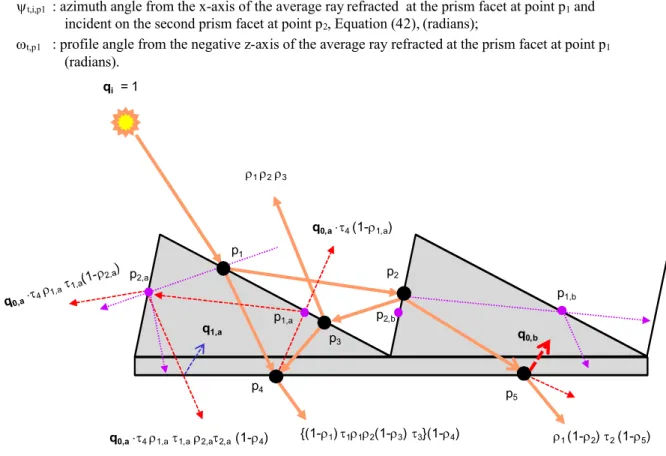
The back optical characteristics of the prismatic pane may be obtained in a similar way when rays are incident on the back pane surface. Figure 3 shows the average ray path when rays are incident on one of the prism facet. Incident rays reflecting off a prism facet may reach the opposite facet, and then may return to the initial facet. Three refracted rays reaching the points p1, p2, and p3should, therefore, be traced in the
pane medium. To simplify the problem, the refracted ray at point p3is assumed to follow the path of the
refracted ray at point p1. The refracted rays within the pane medium may undergo multiple forward
inter-reflections between the prism facets to exit from the planar pane surface. To avoid tracing those multiple inter-reflected rays, only one refection is retained in the model. A refracted ray at point p1may directly
reach the planar surface at point p4, or indirectly after reflecting off the internal surface of the opposite facet
at point p2(equivalent to point p2,ain Figure 3). The refracted ray at point p1reaches the opposite surface at
point p2(p2,a) if its profile angle is greater than a threshold value, expressed as follows:
(17) where:
z,t,i,p1: polar angle from the negative z-axis of the average ray refracted at the prism facet at point p1,
Equation (42), (radians);
t,i,p1 : azimuth angle from the x-axis of the average ray refracted at the prism facet at point p1and
incident on the second prism facet at point p2, Equation (42), (radians);
t,p1 : profile angle from the negative z-axis of the average ray refracted at the prism facet at point p1
(radians).
1 (1-2) 2(1-5)
q0,a41,a1,a2,a2,a(1-4)
qi = 1 p1 p2 p3 p4 q0,b {(1-1) 112(1-3) 3}(1-4) 1 2 3 q1,a p5 q0,a4(1-1,a) p1,a p2,a p1,b p2,b
Figure 3 Average ray’s path when the prism is placed on the front pane surface
Similarly, rays refracted at point p2may directly reach the planar surface at point p5, or indirectly after
reflecting off the internal surface of the opposite facet at point p1. A refracted ray at point p2may reach the
opposite surface at point p1(equivalent to p1,bof Figure 3) if its profile angle is greater than a threshold
(18) where:
z,t,i,p2: polar angle from the negative z-axis of the average ray refracted at the prism facet at point p2,
Equation (42), (radians);
t,i,p2 : azimuth angle from the x-axis of the average ray refracted at the prism facet at point p2and
incident on the second prism facet at point p1, Equation (42), (radians);
t,p2 : profile angle from the negative z-axis of the average ray refracted at the prism facet at point p2
(radians).
Reflected rays at point p4may undergo multiple repetitive reflection cycles between the prism facets
and the planar surface until they decay. Subsequent inter-reflection cycles are assumed to follow the same path as the first reflection cycle. Reflected rays at point p4may travel the path p4- p1,a- p2,a- p4, or p4- p2,a
-p1,a- p4. A reflected ray at point p4is first directed to the surface at point p1,a, or p2,a if the difference
between its azimuth angle (r,i,p4, given by Equation (36)) and that of the surface (1,a, or 2,a) is within
±/2. Similarly, reflected rays at point p5follow the same scenario as those rays reflected at point p4.
Subject to the foregoing assumptions, the back reflectance and transmittance of the pane are obtained using Equations (1) and (2), respectively. The averaging factor (F) is calculated using the following relation:
(19) Where (i) is the profile angle of the incident rays, expressed as follows:
(20) The back reflectance and transmittance of the pane when rays are incident on one of the prism facets (denoted by #1) may be expressed as follows:
(22)
Where 21 is the reflectivity at the internal surface of the prism second facet at point p2,a for rays
refracting from the first prism facet at point p1to reach point p4(see Equation (17)). If the refracted rays at
point p1do not hit the opposite prism facet at point p2,a, 21is set to 1. Similarly, 12is the reflectivity at
the internal surface of the prism first facet at point p1,bfor rays refracting from the second prism facet at
point p2to reach point p5(see Equation (18)). If the refracted rays at point p2do not hit the opposite prism
facet at point p1,b, 12 is set to 1. The interface radiation fluxes (qi,a, qi,b) are recursively given by the
following relations:
(23)
(24) where:
2,a: interface reflectivity for rays incident on the internal surface of the second facet at point p2,a;
2,b: interface reflectivity for rays incident on the internal surface of the second facet at point p2,b;
1,a: interface reflectivity for rays incident on the internal surface of the first facet at point p1,a;
1,b: interface reflectivity for rays incident on the internal surface of the first facet at point p1,b;
2,a: transmissivity for rays reflecting off the internal surface of the second facet at point p2,a;
2,b: transmissivity for rays reflecting off the internal surface of the second facet at point p2,b;
1,a: transmissivity for rays reflecting off the internal surface of the first facet at point p1,a;
1,b: transmissivity for rays reflecting off the internal surface of the first facet at point p1,b.
By substituting Equations (23) and (24) in Equations (21) and (22), one obtains the following relations, after simplification of the series terms:
(26)
It should be noted that a part of the transmitted and reflected radiation fluxes may be treated diffuse due to the inter-reflection in the prism geometry. We define, therefore, the transmission haze as the fraction of the beam-diffuse transmitted flux to the total transmitted flux. Similarly, we define the gloss as the fraction of the dominant beam-beam reflection flux to the total reflection flux. These are expressed as follows:
(27)
(28)
Equations (25) to (28) are developed when the reflected rays at point p4and p5follow the paths p4-p1,a
-p2,a-p4and p5-p1,a-p2,a-p5. If it is not the case, the indices (1,a, or 1,b) are mutually exchanged with the
indices (2,a, or 2,b), respectively in Equations (25) to (28).
The interface transmissivity in Equations (25) to (28) are obtained using Equation (14) after substituting their corresponding incidence angles and the following thicknesses of the media at the points p1, p3, p4, p1,a, and p2,a(or p2, p5, p1,b, and p2,b):
(29)
(30) If the reflected rays at point p1 do not reach the opposite prism facet at point p2, the interface
point p1do not reach the opposite prism facet at point p2if the profile angle of the reflected rays at point p1
is lower than a threshold value (Equation (10)). Similarly, the upward reflected rays at point p2do not hit
the opposite prism facet at point p3if the profile angle of the reflected rays at point p2is lower than a
threshold value (Equation (11)). In this case (that is the upward reflected rays at point p2do not reach point
p3), the interface reflectivity at point p3is set to 3= 1 in Equations (25) and (28). In case, the incident rays
at point p3are reflected downwards between the prism facets, the interface reflectivity at point p3is set to
zero in Equations (25) and (28). Incident rays at point p3are reflected downwards if their polar angle z,r,p3
> /2 (given by Equation (35) ). If the reflected rays off the prism facet at point p1,aafter reflecting off the
surface at point p4do not reach the opposite facet at point p2,a(in case rays reflect back to the surface at
point p4; Equation (17) is thus not satisfied after substituting the rays’ directional angles, z,r,p1,aand r,i,p1,a),
the interface reflectivity at point p2,a is set to 2,a = 1. If they do reach the facet at point p2,a, but the
reflected rays off the facet at point p2,aare upward (z,r,p2,a> /2), the interface reflectivity at point p2,ais set
to 2,a= 0. Similar scenario is applied to points p1,band p2,b.
Again, the directional angles of the reflected and refracted rays at the interface points (p1, p2, p3, p4, p5,
p1,a, p1,b, p2,aand p2,b) are calculated using the formula developed in the Appendix (Equations (32) to (35)
for reflection, and Equations (38) to (41) for refraction) by substituting the tilt and azimuth angles of the interface surfaces. The azimuth angles of the prism facet surfaces (facing the air) are given by the following equation:
(31) The dominant directional angles are evaluated at the interface point p4or p5for the transmitted rays,
and at the interface points p1, p2, p3, p1,a, p2,a, p1,b, or p2,bfor the upward reflected rays, depending on the
magnitude of the transmitted or reflected fluxes at those points.
Model Benchmarking
The previous optical model of prismatic glazing was implemented in the research version of in-house fenestration software tool (Laouadi and Arsenault, 2003; NRC, 2011) to compute the optical characteristics of any combinations of complex panes making up a glazing assembly. The tool’s optical algorithms were
based on splitting the reflected and transmitted radiation fluxes into two components: dominant beam-beam and beam-diffuse components. The dominant beam-beam rays were traced from pane to pane till they exit a glazing assembly from its front and back surfaces. In this regard, the front and back optical characteristics of each pane were calculated based on the dominant directions of the incident rays on the pane’s front and back surfaces. The dominant directions of the transmitted and reflected rays were calculated for each pane based on its geometrical and optical characteristic and the incident ray’s directions. The algorithms by Laouadi and Parekh (2007) were used to compute the overall optical characteristics of a glazing assembly. It should be noted that if the reflected and transmitted dominant beam rays were not traced from pane to pane (by assuming the reflected and transmitted rays follow the directions of the incident rays as it is the case in some fenestration simulation programs), significant calculation errors will result in the transmittance and reflectance of glazing assemblies. In this study, the model predictions for transmittance and reflectance were compared with public data derived from computer ray tracing simulations, and measurement using integrating spheres and goniophometers.
Figure 4 shows a comparison between the present model’s predictions and third-party ray tracing simulations for reflectance of single and double right-angle ( = = 45°) prismatic panes when sunbeam rays were incident on the smooth surface of the prismatic pane perpendicular to the grating direction (i=
90). The prismatic pane was made of a polycarbonate plastic sheet (index of refraction = 1.59). The total pane thickness including the gratings was 0.5 mm, with the grating height making up 25% of the pane thickness. The ray-tracing simulations (Ouellette et al., 1992) used the Monte Carlo approach. The predictions from the simple model of prismatic glazing were in excellent agreement with the detailed ray tracing simulations, particularly for the single glazing. The difference between the simple model and ray tracing for the double glazing was mainly attributed to handling the optics of multi-pane glazing assemblies in which only the dominant beam-beam component was traced from pane o pane.
0.0
0.2
0.4
0.6
0.8
1.0
0
10
20
30
40
50
60
70
80
90
R
ef
le
ct
an
ce
Incidence Angle (deg.)
Ouellete et al. (1992): one pane Present model: one pane Present model: two panes Ouellete et al. (1992): two panes
Figure 4 Model comparison with the ray tracing method for reflectance predictions of a stack of right-angle prismatic panes when rays are incident on the smooth pane surface perpendicular to the grating direction
Figure 5 shows a comparison between the present model predictions and third-party ray tracing simulations for transmittance of single and double right-angle ( = = 45°) prismatic panes when beam radiation was incident on the smooth surface of the prismatic pane. The double glazing was formed by tightly joining together the gratings of two prismatic panes to form a single complemented glazing. The prismatic pane was made of a polycarbonate plastic sheet. The total pane thickness including the gratings was 2.7 mm, with the grating height making up 81.5% of the pane thickness (Seeger, 1969). The ray-tracing simulations (Wirth et al., 1998) used a commercial software tool. The predictions from the simple model compared overall well with the detailed ray tracing simulations, particularly near low and high incidence angles. For intermediate incidence angles (between 15° and 40°), the model predictions were up to 33% higher than the simulations, particularly for the complemented double glazing. This large difference may be attributed to the treatment of the double glazing in the SkyVision’s model and ray tracing software. The SkyVision’s model assumes that the transmitted flux through the first layer is
uniformly incident on the next pane surface (i.e., layers are separated by an air space). This was not the case for the ray tracing method, where both facets of the pane gratings were tightly joined together. Furthermore, it is not clear why the ray tracing simulations produced such profile in the intermediate incidence angles. Other third party measurement for a similar prismatic glazing resulted in a different profile (compare Figure 5 with Figure 8).
0.0
0.2
0.4
0.6
0.8
1.0
0
10
20
30
40
50
60
70
80
90
Tr
an
sm
it
ta
n
ce
Incidence Angle (deg.)
Wirth et al. (1998): single prism Present model: single prism
Wirth et al. (1998): complemented prisms Present model: complemented prisms
Figure 5. Model comparison with a ray tracing method for transmittance of single and double complemented right-angle prismatic glazing when rays are incident on the smooth pane surface perpendicular to the grating direction
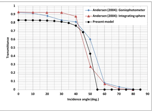
Figures 6 and 7 show a comparison between the present model predictions and third-party measurement for transmittance of right-angle prismatic glazing when radiation was incident on the grating surface perpendicular (i= 90) and parallel (i= 0) to the grating direction, respectively. The prismatic
glazing was formed by applying a prismatic thin film on a 6 mm clear glass. The prismatic film was made of a polycarbonate plastic material with a total thickness of 0.686 mm and a grating height of 26% of the film thickness (3M, 2000). The present model treated the prismatic glazing as a double glazing (3M film,
air space, glass) since it was not indicated whether the film was glued to, or merely placed on the glass pane (Anderson, 2004). The third party measurement data were obtained using the integrating sphere and goniophotometer procedures. Given the simplicity of the present model, and the large difference between the two measurement procedures (up to 42% deviation), the model predictions compared overall well with the measurement for all incidence angles. Furthermore, the difference between the model’s predictions and measurement may also be attributed to the non-ideal (rounded edges of as-manufactured) prismatic samples, and dust accumulation in the grating spaces.
0 0.1 0.2 0.3 0.4 0.5 0.6 0.7 0.8 0.9 1 0 10 20 30 40 50 60 70 80 90 Tr an sm itt an ce
Incidence angle (deg.)
Andersen (2004): Goniophotometer Andersen (2004): Integrating sphere Present model
Figure 6 Model comparison with measurement for a right-angle prismatic film over glass pane when rays are incident on the grating surface and perpendicular to the grating direction
0 0.1 0.2 0.3 0.4 0.5 0.6 0.7 0.8 0.9 1 0 10 20 30 40 50 60 70 80 90 Tr an sm itt an ce
Incidence angle (deg.)
Andersen (2004): Goniophotometer Andersen (2004): Integrating sphere Present model
Figure 7 Model comparison with measurement for a right-angle prismatic film over glass pane when rays are incident on the grating surface and parallel to the grating direction
Figure 8 shows a comparison between the present model predictions and a third-party measurement for transmittance of a prismatic glazing when beam radiation was incident on the glass surface perpendicular to the grating direction. Again, given the large difference between the two measurement procedures, the model predictions compared overall well with the measurement, particularly for low and high incidence angles. The model over-predicted the transmittance by up to 26% for intermediate incidence angles (between 15° and 35°).
0 0.1 0.2 0.3 0.4 0.5 0.6 0.7 0.8 0.9 1 0 10 20 30 40 50 60 70 80 90 Tr an sm itt an ce
Incidence angle (deg.)
Andersen (2004): Integrating sphere Andersen (2004): Goniophotometer Present model
Figure 8 Model comparison with measurement for a right-angle prismatic film under glass pane when rays are incident on the smooth film surface and perpendicular to the grating direction
Figure 9 shows a comparison between the present model predictions and third-party measurement for transmittance of an asymmetric ( = 42°, =°5) prismatic glazing when radiation was incident on the grating surface parallel to the grating direction. The prismatic glazing was made of an acrylic sheet (index of refraction = 1.49) with a total pane thickness of 12 mm and a grating height of 58% of the pane thickness. Again, the model predictions compared overall well with the measurement for all incidence angles.
0 0.1 0.2 0.3 0.4 0.5 0.6 0.7 0.8 0.9 1 0 10 20 30 40 50 60 70 80 Tr an sm itt an ce
Incidence angle (deg.) Andersen (2004): Goniophotometer
Andersen (2004): Integrating sphere Present model
Figure 9 Model comparison with measurement for an asymmetric (= 42°, = 5°) prismatic pane when rays are incident on the grating surface and parallel to the grating direction
Conclusion
This paper presented the development and validation of a simplified model to compute the spectral (monochromatic) or broad-band optical characteristics (transmittance, reflectance, and absorptance) and dominant directions of the transmitted and reflected beam rays of saw-took like prismatic glazing. The model was based on tracing the average ray, and was extensively validated using third-party data derived from detailed ray tracing computer simulations, and measurement using integrating spheres and goniophotometers. The model’s predictions for the transmittance and reflectance of single and double prismatic panes compared overall well within the accuracy of the third-party data over all incidence angles.
The model may easily be implemented in fenestration computer design tools with a quick calculation time (in seconds) for the hemispheric transmitted and reflected radiation fluxes compared to detailled ray tracing programs, which need to trace a large number (thousands) of rays with a proportional calculation
time (in hours). To produce accurate results for a multi-pane glazing assembly containing a number of prismatic (or other complex) panes, the fenestration computer program should employ an optical algorithm in which the dominant beam rays with their angular direction are traced from pane to pane till they exit the glazing assembly from its front and back surfaces.
Nomenclature
F : averaging factor
k : attenuation coefficient of medium (m-1, ft-1)
n : index of refraction of a medium
q : ratio of interface to incident radiation flux t : thickness of medium (m, ft)
Greek symbols
: wave length of radiation (m, ft).
: polar angle from the z-axis of a surface normal (radians) : polar angle from the vertical (radians);
: interface reflectivity, or pane reflectance : transmissivity of medium
: profile angle from the z-axis of incident ray on a tilted surface (radians). : azimuth angle from the x-axis of a surface normal (radians);
Appendix: Directional Angles of Transmitted, Refracted and Reflected rays
Consider a conical beam ray with directional zenith and azimuth angles (i, i) incident on a ‘complex’
glazing surface with tilt and azimuth angles (p, p). The glazing medium is bounded by two media at its
front and back surfaces. Upon contact with the glazing surface, incident rays may undergo reflection back in the incidence medium, refraction in the glazing medium, and transmission to the exit medium. By virtue of the laws of optics (Tunnacliffe and Hirst, 1996), reflected, refracted and transmitted rays are in the same plane containing the incidence direction and surface normal. For the purpose of clarity, we use the same notations for the transmitted and refracted rays. Figure 10 shows the paths for the reflected and refracted or transmitted rays. The geometric and optical characteristic of the glazing medium may change the directions of the reflected and refracted or transmitted rays in such a way the refracted or transmitted rays follow the direction (t, t) and the reflected rays follow the direction (r, r). For example, for plain
glazing with smooth surfaces, the transmitted rays through the glazing will follow the direction of the incident rays (t= i; t= i), and the reflected rays will follow the specular (mirror) direction. The
directions of the refracted rays in the glazing medium are governed by Snell’s law. If the glazing surface is rough or with some built-in optical devices such as prisms or lenses, the directions of the refracted, transmitted and reflected rays will be different from those for a smooth surface. In this case, geometrical optics should be applied to calculate the directional angles of the refracted, transmitted and reflected rays (provided that the radiation wavelengths are significantly smaller than the size of the built-in optical devices). In the following, a method is presented to compute the directional angles of the refracted, transmitted and reflected rays based on the directional angles of the incident rays on the surface.
Applying the spherical trigonometry to the incident and reflected ray directions, one obtains:
(32) (33) (34) where:
p : tilt angle of the glazing surface from a horizontal plane (radians);
r : polar angle of the reflected rays from the normal of a horizontal plane (radians);
p : azimuth angle of the tilted glazing surface from the south (or any reference) direction (radians);
r : azimuth angle of the reflected rays from the south (or any reference) direction (radians);
i : incidence angle between the incident ray’s direction and the glazing surface normal (radians);
r : reflection angle between the reflected ray’s direction and the glazing surface normal (radians).
The reflection angle (r) is usually known for plain glazing with smooth surfaces (r= i), or
pre-calculated using the geometrical optics for complex glazing with known geometries. The directional angles (r, r) of the reflected rays are obtained by solving the non-linear Equations (32) and (34). Tregenza
(1993) gave a closed-form formulation, in which the polar angle of reflection (r) is expressed as follows:
(35) The azimuth angle of reflection (r) is thus obtained from Equation (33) or (34) after substituting the
value of the known reflection angle (r). To avoid multiple solutions, the obtained value of (r) should
satisfy both Equations (33) and (34).
When the reflected rays from the glazing surface under consideration are incident on another glazing surface sharing the same or opposite direction of the z-axis, the polar and azimuth angles of the incoming reflected rays (r,i, r,i) on the other surface will take the following form, respectively:
(36) (37) The directional angles (t, t) of the refracted rays at an interface between two media are obtained as
follows (Stavroudis, 1976):
(38) (39) (40)
(41) where:
n1 : index of refraction of the incidence medium 1;
n2 : index of refraction of the refraction medium 2;
t : polar angle of the refracted rays from the normal of a horizontal plane (radians);
t : azimuth angle of the refracted rays from the south (or any reference) direction (radians);
t : refraction angle between the refracted ray’s direction and the interface normal (radians).
Equations (38) and (41) are solved first to obtain the value of t, which is then substituted in Equation
(39) or (40) to obtain (t). To avoid multiple solutions, the value of (t) should satisfy both Equations
(39) and (40).
Equations (38) to (41) are applied to any interface between two media. The direction of the transmitted rays exiting the glazing medium is thus equal to the direction of the last refracted rays.
When the refracted rays at an interface become incident on another interface sharing the same or opposite direction of the z-axis, the polar and azimuth angles of the incoming refracted rays on the other interface take the following form, respectively:
(42) (43) It should be added that Equations (38) to (43) are not needed for plain glazing with smooth surfaces, for which the transmission angles of rays exiting the glazing medium are equal to the incidence angles (t=
i p r Normal i South direction Reflected ray
Refracted or transmitted ray Incident ray i r t r vertical t p t
Figure 10 Directional angles of refracted (or transmitted) and reflected rays for a planar tilted glazing surface
References
3M. 2000. 2301 Optical Lighting Film. Technical Specification. Minnesota: 3M.
Andersen M. 2003. Comparison between ray-tracing simulations and bi-directional transmission measurements on prismatic glazing. Solar Energy, 74; 157-173.
Andersen M. 2004. Innovative bidirectional video-goniophotometer for advanced fenestration systems. Ph.D. thesis. École polytechnique fédérale de Lausanne. Switzerland.
Andersen M. 2006. Validation of the performance of a new bidirectional video-goniophometer. Lighting Research and Technology, 38(4); 295-313.
Blasi B., Gombert A., and Niggemann M. 2010. Microstructural polymer surfaces with complex optical functions for solar applications. The handbook of environmental chemistry, volume 2: Sustainability, product design and processing: Polymers - opportunities and risks; 263-279.
Chen J. Wang Q., and Li H. 2010. Microstructured design for light trapping in thin-film silicon solar cells. Optical Engineering, 49; 88001-88009.
Critten D.L., 1998. Light enhancement using E-W aligned long prismatic arrays at high latitude, Solar Energy, 41(6); 583-591.
Gombert A., B., Buhler C., Hofeld W., Mick J., Blasi B., Walze G., and Nitz P. 20104a. A rigorous study of diffraction effects on the transmission of linear dielectric micro-reflector arrays. J. Optics A: Pure and Applied Optics, 6; 952-960.
Gombert A., Blasi B., Buhler C., and Nitz P. 20104b. Some application cases and related manufacturing technique for optically functional microstructures on large areas. Opt. Eng. 43(11); 2525-2533. Hocheng H., Huang T.Y., Chou T.H., and Yang W.H. 2010. A brighter place: overview of microstructured
sunlight guide. J. Achievements in Materials and Manufacturing Engineering, 43(1); 409-417.
Hocheng H., Huang T.Y., Chou T.H., and Yang W.H. 2011. Microstructural fabrication and design of sunlight guide panels of inorganic-organic hybrid material. Energy and Buildings, 43; 1011-1019. Klammt S., Neyer A., and Muller H.F.O. 2012. Redirection of sunlight by microstructured
components-simulation, fabrication and experimental results. Solar Energy, 86; 1160-1666.
Laouadi, A., Arsenault, C.D. 2003. Validation of skylight performance assessment software. ASHRAE Transactions, 112, (Pt. 2); 1-13.
Laouadi A., Parekh A. 2007. Optical models of complex fenestration systems, Lighting Research and Technology, 39(2); 123-145.
Laouadi, A., 2011. The Central Sunlighting System: development and validation of an optical prediction model. Journal of Building Performance Simulation, 4(3); 205-226.
Laouadi A., and Coffey B., 2012. The energy performance of the Central Sunlighting System. Journal of Building Performance Simulation, 5(4); 234-247.
Lorenz W. 2001. A Glazing unit for solar control, daylighting and energy conservation. Solar Energy, 70; 109-130.
NRC. 2011. SkyVision v1.2.1 National Research Council of Canada. Available for free download from:
http://irc.nrc-cnrc.gc.ca/ie/light/skyvision/[Accessed September 2011].
Ouellette G., Waltham C.E., Drees R.M., Poon A., and Schubank R. 1992. Nonimaging light concentration using total internal reflection film. Applied Optics, 31(13); 2360-2365.
ODL. 2012. ODL Inc. www.odl.com. Accessed in May 2012.
Saxe S.G. 1989. Prismatic film light guides: performance and recent developments. Solar Energy Materials, 19; 95-109.
Seeger B.I. 1969. Optical control of sunlight at window and door openings with controlled positioning of composite transparent materials to eliminate glaring sunlight rays while providing normal daylight illumination. US patent No. 3438699.
Siegel R. and Howell J. 2002. Thermal radiation heat transfer. Fourth edition. Taylor & Francis. New York.
Slaman M. and Griessen R. 2009. Solar collector overheating protection. Solar Energy 83; 982–987. Solatube. 2012. Solatube International Inc. www.solatube.com. Accessed in May 2012.
Stavroudis O.N. 1976. Simpler derivation of the formulas for generalized ray tracing. J. Opt. Soc. Am. 66, 1330-1333.
Skydome. 2012. Skydome Skylight Systems. www.skydome.com.au. Accessed in May 2012.
Tregenza P. 1993. Daylighting Algorithms. Report ETSU S 1350. School of Architecture Studies, University of Sheffield, UK.
Tunnacliffe, A.H., and Hirst J.G. 1996. Optics. Kent, England. 2337.
Walze G., Nitz P., Ell J., Georg A., Gombert A., and Hossfeld W. 2005. Combination of microstructures and optically functional coatings for solar control glazing. Solar Energy Materials and Solar Cells, 89; 233-248.
Whitehead, L., Nodwell, R., Curzon, F., 1982. New efficient light guide for interior illumination. Appl. Opt. 21 (15), 2755–2757.
Wirth H., Gombert A., Wittwer V., and Luther J. 1998. Directionally selective dielectric structures for solar radiation control. Solar Energy, 63(4); 296-275.