HAL Id: hal-03001187
https://hal.archives-ouvertes.fr/hal-03001187
Submitted on 12 Nov 2020
HAL is a multi-disciplinary open access
archive for the deposit and dissemination of
sci-entific research documents, whether they are
pub-lished or not. The documents may come from
teaching and research institutions in France or
abroad, or from public or private research centers.
L’archive ouverte pluridisciplinaire HAL, est
destinée au dépôt et à la diffusion de documents
scientifiques de niveau recherche, publiés ou non,
émanant des établissements d’enseignement et de
recherche français ou étrangers, des laboratoires
publics ou privés.
The Solar Orbiter EUI instrument: The Extreme
Ultraviolet Imager
P. Rochus, F. Auchère, D. Berghmans, L. Harra, W. Schmutz, U. Schühle, P
Addison, T. Appourchaux, R. Aznar Cuadrado, D Baker, et al.
To cite this version:
P. Rochus, F. Auchère, D. Berghmans, L. Harra, W. Schmutz, et al.. The Solar Orbiter EUI
instru-ment: The Extreme Ultraviolet Imager. Astronomy and Astrophysics - A&A, EDP Sciences, 2020,
642, �10.1051/0004-6361/201936663�. �hal-03001187�
https://doi.org/10.1051/0004-6361/201936663 c ESO 2020
Astronomy
&
Astrophysics
The Solar Orbiter mission
Special issue
The Solar Orbiter EUI instrument: The Extreme Ultraviolet Imager
P. Rochus
1, F. Auchère
2, D. Berghmans
3, L. Harra
4, W. Schmutz
5, U. Schühle
6, P. Addison
4, T. Appourchaux
2,
R. Aznar Cuadrado
6, D. Baker
4, J. Barbay
2, D. Bates
4, A. BenMoussa
3, M. Bergmann
6, C. Beurthe
7, B. Borgo
2,
K. Bonte
3, M. Bouzit
2, L. Bradley
4, V. Büchel
5, E. Buchlin
2, J. Büchner
6, F. Cabé
2, L. Cadiergues
9, M. Chaigneau
2,
B. Chares
6, C. Choque Cortez
2, P. Coker
4, M. Condamin
2, S. Coumar
7, W. Curdt
6, J. Cutler
4, D. Davies
4,
G. Davison
4, J.-M. Defise
1, G. Del Zanna
8, F. Delmotte
7, V. Delouille
3, L. Dolla
3, C. Dumesnil
2, F. Dürig
5,
R. Enge
6, S. François
2, J.-J. Fourmond
2, J.-M. Gillis
1, B. Giordanengo
3, S. Gissot
3, L. M. Green
4, N. Guerreiro
5,
A. Guilbaud
7, M. Gyo
5, M. Haberreiter
5, A. Hafiz
4, M. Hailey
4, J.-P. Halain
1, J. Hansotte
2, C. Hecquet
7,
K. Heerlein
6, M.-L. Hellin
1, S. Hemsley
4, A. Hermans
1, V. Hervier
2, J.-F. Hochedez
3, Y. Houbrechts
1, K. Ihsan
4,
L. Jacques
1, A. Jérôme
7, J. Jones
4, M. Kahle
6, T. Kennedy
4, M. Klaproth
6, M. Kolleck
6, S. Koller
5, E. Kotsialos
4,
E. Kraaikamp
3, P. Langer
5, A. Lawrenson
4, J.-C. Le Clech’
2, C. Lenaerts
1, S. Liebecq
1, D. Linder
4, D. M. Long
4,
B. Mampaey
3, D. Markiewicz-Innes
6, B. Marquet
1, E. Marsch
6, S. Matthews
4, E. Mazy
1, A. Mazzoli
1, S. Meining
6,
E. Meltchakov
7, R. Mercier
7, S. Meyer
6, M. Monecke
6, F. Monfort
1, G. Morinaud
2, F. Moron
7, L. Mountney
4,
R. Müller
6, B. Nicula
3, S. Parenti
2,3, H. Peter
6, D. Pfi
ffner
5, A. Philippon
2, I. Phillips
4, J.-Y. Plesseria
1, E. Pylyser
3,
F. Rabecki
1, M.-F. Ravet-Krill
7, J. Rebellato
7, E. Renotte
1, L. Rodriguez
3, S. Roose
1, J. Rosin
1, L. Rossi
1, P. Roth
7,
F. Rouesnel
2, M. Roulliay
7, A. Rousseau
4, K. Ruane
4, J. Scanlan
4, P. Schlatter
5, D. B. Seaton
3,?, K. Silliman
4,
S. Smit
4, P. J. Smith
4, S. K. Solanki
6, M. Spescha
5, A. Spencer
4, K. Stegen
3, Y. Stockman
1, N. Szwec
2, C. Tamiatto
2,
J. Tandy
4, L. Teriaca
6, C. Theobald
4, I. Tychon
1, L. van Driel-Gesztelyi
4, C. Verbeeck
3, J.-C. Vial
2, S. Werner
6,
M. J. West
3, D. Westwood
4, T. Wiegelmann
6, G. Willis
4, B. Winter
4, A. Zerr
6, X. Zhang
2, and A. N. Zhukov
31 Centre Spatial de Liège, Université de Liège, Av. du Pré-Aily B29, 4031 Angleur, Belgium
2 Institut d’Astrophysique Spatiale, CNRS, Univ. Paris-Sud, Université Paris-Saclay, Bât. 121, 91405 Orsay, France 3 Royal Observatory of Belgium, Ringlaan -3- Av. Circulaire, 1180 Brussels, Belgium
e-mail: [email protected]
4 UCL-Mullard Space Science Laboratory, Holmbury St. Mary, Dorking, Surrey RH5 6NT, UK
5 Physikalisch-Meteorologisches Observatorium Davos, World Radiation Center, 7260 Davos Dorf, Switzerland 6 Max Planck Institute for Solar System Research, Justus-von-Liebig-Weg 3, 37077 Göttingen, Germany
7 Laboratoire Charles Fabry, Institut d’Optique Graduate School, Université Paris-Saclay, 91127 Palaiseau Cedex, France 8 Centre for Mathematical Sciences, University of Cambridge, Wilberforce Road, Cambridge CB3 0WA, UK
9 Centre National d’Etudes Spatiales, 18 avenue Edouard Belin, 31401 Toulouse Cedex 9, France Received 10 September 2019/ Accepted 5 December 2019
ABSTRACT
Context.The Extreme Ultraviolet Imager (EUI) is part of the remote sensing instrument package of the ESA/NASA Solar Orbiter mission that will explore the inner heliosphere and observe the Sun from vantage points close to the Sun and out of the ecliptic. Solar Orbiter will advance the “connection science” between solar activity and the heliosphere.
Aims.With EUI we aim to improve our understanding of the structure and dynamics of the solar atmosphere, globally as well as at high resolution, and from high solar latitude perspectives.
Methods.The EUI consists of three telescopes, the Full Sun Imager and two High Resolution Imagers, which are optimised to image in Lyman-α and EUV (17.4 nm, 30.4 nm) to provide a coverage from chromosphere up to corona. The EUI is designed to cope with the strong constraints imposed by the Solar Orbiter mission characteristics. Limited telemetry availability is compensated by state-of-the-art image compression, onboard image processing, and event selection. The imposed power limitations and potentially harsh radiation environment necessitate the use of novel CMOS sensors. As the unobstructed field of view of the telescopes needs to protrude through the spacecraft’s heat shield, the apertures have been kept as small as possible, without compromising optical performance. This led to a systematic effort to optimise the throughput of every optical element and the reduction of noise levels in the sensor.
Results.In this paper we review the design of the two elements of the EUI instrument: the Optical Bench System and the Common Electronic Box. Particular attention is also given to the onboard software, the intended operations, the ground software, and the foreseen data products.
Conclusions.The EUI will bring unique science opportunities thanks to its specific design, its viewpoint, and to the planned synergies with the other Solar Orbiter instruments. In particular, we highlight science opportunities brought by the out-of-ecliptic vantage point of the solar poles, the high-resolution imaging of the high chromosphere and corona, and the connection to the outer corona as observed by coronagraphs.
Key words. Sun: UV radiation – Sun: transition region – Sun: corona – space vehicles: instruments – telescopes – instrumentation: high angular resolution
1. Introduction: Instrument overview
The ESA Solar Orbiter mission is designed to determine how the Sun creates and controls the heliosphere (Garcia-Marirrodriga et al. 2020). The spacecraft will bring a combination of in situ (Horbury et al. 2020) and remote-sensing instruments (Auchère et al. 2020) out of the ecliptic (>30◦) and close to the Sun (<0.3 AU), to answer the following four questions (Müller et al. 2020):
1. What drives the solar wind and where does the coronal mag-netic field originate?
2. How do solar transients drive heliospheric variability? 3. How do solar eruptions produce energetic particle radiation
that fills the heliosphere?
4. How does the solar dynamo work and drive connections between the Sun and the heliosphere?
As part of the remote-sensing instrument package of Solar Orbiter, the Extreme Ultraviolet Imager (EUI) will contribute to answering all four questions through the observation of struc-tures and events in the solar atmosphere. The EUI instrument is composed of two units, the Optical Bench System (OBS) and the Common Electronics Box (CEB), which are linked by an inter-connecting harness.
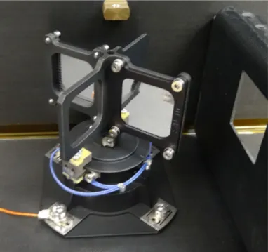
The OBS (Fig.1) is a common structure holding the three telescopes with mirrors, cameras, filter wheels, filters, and door mechanism subsystems. These three complementary telescopes will collectively cover the range from the chromosphere to the outer corona, and image this range globally, at very high reso-lution and from high-latitude perspectives. The two High Reso-lution Imagers (HRIs) are two-mirror optical systems while the Full Sun Imager (FSI) is a one-mirror telescope, each working in near normal incidence. Spectral selection is obtained with spe-cific multi-layered coatings on the mirrors, complemented by fil-ters that reject the visible and infrared radiation.
The (E)UV photons are collected on CMOS1 Active Pixel Sensors (APS) of 3072 × 3072 pixels of 10 µm each. For the HRI channels the sensors are windowed to 2048 × 2048 illu-minated pixels. The FSI and the HRIEUV use the APS sensor in a backside thinned configuration, while the HRILya uses the APS sensor in a front-sided configuration in conjunction with an image intensifier. For each detector pixel, the resulting sig-nal is proportiosig-nal to the solar flux corresponding to the small viewing angle of the pixel in the given pass band. The elec-trical signals are converted to digital numbers in the front-end camera electronics, before being compressed and stored in the CEB. The CEB (Fig. 2) operates the instrument and provides the data handling (processing and compression) of the three telescopes.
The EUI OBS and EUI CEB are both mounted on the so-called payload “MY” panel (a large optical bench) on the −Y side of the spacecraft, together with other remote-sensing instruments (Garcia-Marirrodriga et al. 2020). The EUI baffles pierce through cut-outs in the top floor “PX” panel of the space-craft (+X side) where they connect to the corresponding feed-throughs of the spacecraft heat shield (see Fig.3). The two HRI apertures are protected by a common heat shield door. The FSI aperture is protected by a second, separate heat shield door. In addition, each telescope has its own instrument door protecting the optical entrance aperture. Operating an EUI telescope thus requires that both the corresponding heat shield door and instru-ment door are opened.
1 Complementary Metal-Oxide-Semiconductor.
Fig. 1.Photo (top) and schematic (bottom) of the EUI OBS showing internal subsystems.
Fig. 2.CEB of EUI with the top and front panels removed.
2. Scientific objectives
In the following three sections we briefly highlight some science questions that EUI will be able to address thanks to the combina-tion of its specific design, the unique orbit that Solar Orbiter will embark on, and to joint campaigns with the other Solar Orbiter instruments.
2.1. The transition from corona to the heliosphere
The large-scale structure of the low corona is determined by active regions, filament channels and coronal holes whose pres-ence and location have a clear evolution over the solar cycle.
Fig. 3.EUI thermal interfaces overview showing the HE, ME, and CE connections.
Higher up in the corona, streamers and pseudo streamers, which arch over the active regions and filaments, stretch out into the heliospheric plasma sheet. This magnetic connection region between the corona and the heliosphere is of particular phys-ical interest because it is here that the structures change from being magnetically dominated to being controlled by the plasma outflow.
When trying to determine the coronal foot-point of features observed by the in situ instruments, the transition from corona to heliosphere introduces significant uncertainty as the extrap-olations from the photosphere have to be mapped to a Parker-spiral-type configuration. Deciphering this connection is thus of primordial importance for Solar Orbiter connection science. This “transition” corona (approximately one to three solar radii above the solar limb) is poorly studied as it corresponds to the gap in the field of view (FOV) between most previous EUV imagers and coronagraphs (Slemzin et al. 2008;Masson et al. 2014;Reva et al. 2016;O’Hara et al. 2019). The EUI Full Sun Imager (FSI) will be imaging alternatively in the 17.4 nm and 30.4 nm EUV pass-bands, with a 3.8◦× 3.8◦FOV, corresponding to (14.3 R
)2 at 1 AU and still (4.0 R )2 at perihelion. This FOV is unprece-dentedly large for a coronal EUV imager and will have a sig-nificant overlap (Auchère et al. 2020) with the Solar Orbiter coronagraph Metis (Antonucci et al. 2020).
Recent image mosaics collected by the Solar Ultraviolet Imager (SUVI) during exceptional off-points of the Geosta-tionary Operational Environmental Satellite (GOES;Tadikonda et al. 2019, see Fig. 4) reveal that coronal structures indeed extend to several solar radii. Unexpected structures have been observed in the transition corona by the HeCOR2and SCORE3 coronagraphs (FSI and METIS prototypes,Auchère et al. 2007; Romoli et al. 2007) on the HERSCHEL4 sounding rocket (see online5andMoses et al. 2020) and by the SWAP6 EUV imager
(Seaton et al. 2013b). In contrast to SWAP, the FSI detector will be cooled to −40◦C, thus allowing deep exposures that are impossible to achieve with SWAP.
The large FSI FOV is designed to guarantee that even for maximal off-points by Solar Orbiter, the full solar disc remains in the FOV. The FSI will thus provide a view on the global mor-phology of the solar atmosphere (active regions, coronal holes, quiet Sun), thereby setting the scene in which the first Solar Orbiter science question above will be settled. As required for the second and third science question above, FSI will help us to understand the initial phase of solar eruptive processes (Green 2 Helium CORonagraph.
3 Solar CORonograph Experiment.
4 HElium Resonant Scattering in the Corona and HELiosphere. 5 http://metis.oato.inaf.it/score.html
6 Sun Watcher using Active Pixel System detector and Image Processing.
Fig. 4.Mosaics created by a series of off-pointings by the GOES/SUVI instrument, demonstrating EUV structures up to several solar radii (adapted fromTadikonda et al. 2019). The FOV shown in this figure cor-responds to the FSI FOV at perihelion. Even with extreme off-pointing to the solar limb (right panel, white cross), the full solar disc remains in the FOV.
et al. 2018) such as flares, coronal mass ejections (CMEs) in the corona. For all these reasons, EUI will be an essential building block for the “connection science” to which all Solar Orbiter instruments will contribute.
2.2. The solar atmosphere at high resolution
After decades of investigations, there is still no full picture of why the corona, as the lower boundary of the heliosphere, actually exists: both the replenishment of energy as well as the replenishment of mass are not fully understood. How does the solar corona maintain its temperature and how is the solar wind mass loss compensated? Although the biggest energy releases (solar flares) and biggest mass expulsions (CMEs) can make enormous contributions, they are too sporadic in nature to explain the persistent existence of the corona. A general consen-sus exists that the crucial processes responsible for the forma-tion of the corona must therefore be operating at small scales throughout the corona at all times.
The FSI is therefore accompanied by two high-resolution imagers (HRIs) to image fine structures and small-scale events in the solar atmosphere. The pass-bands of the HRIs are compa-rable to each of the pass-bands of FSI. The HRI imaging in the EUV (“HRIEUV”) at 17.4 nm corresponds to the 17.4 nm chan-nel of FSI. The second HRI, which images in the Lyman-α line (“HRILya”), shares the same resonance formation process for hydrogen as the 30.4 nm channel of FSI for helium. In this way, EUI covers emission from the high chromosphere to the low corona, both at high resolution and at global scales. The HRIs have been designed to have a two-pixel resolution of 1 arcsec, which corresponds to a pixel footprint on the Sun of (100 km)2 during the perihelion observations. At this resolution, proper temporal sampling of features propagating at the sound speed of 150 km s−1in a 1 MK plasma implies an imaging cadence of the order of seconds. Both HRI cameras are capable of oper-ating at 1 second imaging rates and faster in subfields. With a 2048 × 2048 pixel array, the HRIs will image a 170× 170FOV, corresponding to (1 R )2 when imaging at 1 AU and (0.28 R )2 at perihelion.
Until now, such temporal and spatial resolution has only been achieved by imagers on short duration sounding rockets such as Hi-C (Kobayashi et al. 2014) for coronal imaging and VAULT (Korendyke et al. 2001; Vourlidas et al. 2010) for Lyman-α imaging. Such observations have yielded exciting new results but remain hampered by small event number statistics: Hi-C was
capable of resolving for the first time braiding of loop strands, but only two cases could be identified (Cirtain et al. 2013).Pant et al. (2015) studied flows and waves in a braided structure but they were limited to the 200 s duration of the Hi-C dataset. VAULT observations of an individual spicule (Chintzoglou et al. 2018) combined with IRIS (De Pontieu et al. 2014) data showed the spicule as a moving heating front without the need to assume any mass flow.
To obtain the richest possible datasets, the EUI HRI tele-scopes will be operated in joint campaigns with the Solar Orbiter spectrograph SPICE (SPICE Consortium 2020) and the PHI high-resolution telescope (HRT, Solanki et al. 2020). Teleme-try limitations will not allow continuous HRI operations but nevertheless HRI image sequences of different targets will be taken regularly in different phases of the solar cycle and from increasing solar latitude perspectives. The HRI image sequences will provide unprecedented opportunities to study the fine struc-ture in the solar low corona (loops, filaments, etc.) and the dynamics (waves, flows, jets, nano-flares, etc.) therein. A spe-cific science objective of the EUI HRI telescopes is to under-stand the physical mechanisms producing and operating in the hot solar atmosphere, as this is the driving boundary of the whole heliosphere.
2.3. The high-latitude perspective
The EUI instrument will bring unique science opportunities not only because of its own design but also because of the unique orbit the platform embarks on (Garcia-Marirrodriga et al. 2020). With the help of a number of Venus gravity assist manoeuvres, the orbit of Solar Orbiter will gradually be lifted out of the plane of the ecliptic. More than 30◦ solar latitude will be reached, which is sufficient to observe a solar pole entirely in a single image.
It is well known that the solar activity cycle is driven by a global dynamo, but it has been difficult to constrain this due to the lack of polar observations. In addition, there also exists evidence for a local dynamo, which can re-process magnetic field (Stenflo 2013). The particular magnetic field distribution in polar coronal holes implies that there could be differences in the behaviour and activity in the polar atmosphere as compared to lower-latitude regions.Harra et al.(2015) carried out a long-term study of polar regions with Hinode EIS and SDO AIA and found that the coronal non-thermal velocities measured in the polar region remained unchanged during the cycle, which was interpreted as a local dynamo effect. The number of bright points also remained unchanged.
The EUI will be able to explore the polar view of the con-vective cell boundaries using HRILya, and investigate bright points, jets, plumes, and spicules in the polar region using both HRIs during Solar Orbiter off-points. Polar features observed from high latitude can be compared stereoscopically with EUV imagers in the ecliptic plane. “Earth-view” observations indi-cate that statistics of small-scale dynamics remain constant throughout the cycle. The Solar Orbiter out-of-ecliptic view will undoubtedly transform our view of the poles and activity there. This will be done together with PHI, which will measure the polar magnetic field from an unprecedented point of view, and SPICE, which will measure the thermal dynamics, and Doppler and non-thermal velocities in these same structures in order to provide a comprehensive view on how the magnetic field dynam-ics transfer the magnetic energy to the solar plasma and produce these dynamical structures.
The fast solar wind emanates from the poles, and there will be many opportunities for comparison between EUI images and
in situ observations of the fast solar wind, either at the Solar Orbiter location or elsewhere. In particular, dynamic features can be pursued, thereby uncovering the source(s) of the fast solar wind. Together with the Solar Orbiter PHI instrument, FSI will also play an important supportive role when the spacecraft is located in opposition to the Earth: imagery of the solar far-side showing the location of coronal holes and active regions will support 3D modelling of the solar coronal magnetic field con-tributing to the interpretation of the in situ solar wind data.
The other huge advantage of the out-of-ecliptic view will be the observations of the active latitudes from above. The FSI will be able to view eruptions from this novel angle. In addition, an occulter is available in FSI to allow exploration of the fainter corona further away from the solar surface.
2.4. From constraints to technological innovation
The specifics of Solar Orbiter as a deep-space and near-Sun mis-sion imposes challenging constraints on the design and the oper-ation of the EUI telescopes. In the following sections, we present how the EUI instrument was designed and built for maximal sci-entific exploitation in the presence of the imposed constraints.
For example, Solar Orbiter’s proximity to the Sun during part of the orbit dictated that the telescope apertures in the heat shield must be small. This led to a systematic effort to optimise the throughput of every optical element and the reduction of noise levels in the sensor. Given the limited apertures, the selection of the different pass-bands of the telescopes was constrained to the brightest parts of the spectrum. These aspects are covered in Sect.3on the optical design, while the mechanical and thermal design is presented in Sect.4.
The imposed power limitations and potentially harsh radia-tion environment led to the usage of novel CMOS-APS (see next section) sensors, previously pioneered in orbit for solar physics by the PROBA2/SWAP telescope (Seaton et al. 2013a; Halain et al. 2013). The telemetry available to EUI is orders of magni-tude smaller than the data-production potential of the instrument. Maximisation of the science return of the instrument therefore implies maximising the science content of every bit of teleme-try. The strategy to achieve this includes onboard processing, event selection, and state-of-the-art data compression. The hard-ware implementing all these functions is described in Sect.5on electronics.
The expected performance of the instrument is described in Sect.8, and Sect.9lists the concepts of operations. Final con-clusions are collected in Sect.10.
3. Optics
3.1. Full Sun Imager
The FSI was designed according to the following top-level requirements:
– A FOV width of two solar diameters at perihelion so that the whole Sun can be seen when the spacecraft is pointed at the solar limb.
– An angular resolution of 10 arcsec.
– Two pass-bands centred on 30.4 nm and 17.4 nm to image the transition region and the EUV corona, with a spectral purity better than 80 and 90% respectively.
– Typical exposure times of a few seconds to be able to freeze the expected dynamics given the angular resolution.
These requirements, in combination with the efficiency of the available optics, dictated a relatively large entrance pupil.
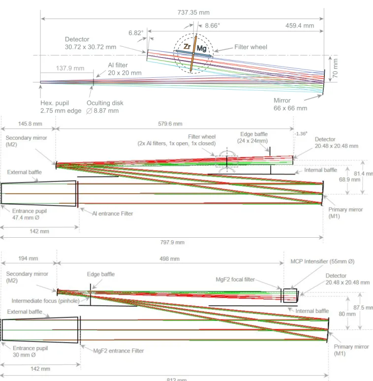
Zr Zr MgMg Hex. pupil 2.75 mm edge Mirror 66 x 66 mm 459.4 mm 70 mm Filter wheel 6.82° 8.66° Detector 30.72 x 30.72 mm Al filter 20 x 20 mm Oculting disk 8.87 mm 737.35 mm 137.9 mm
Fig. 5.Optical scheme with the positions and coordinates of the components of the three telescopes: the FSI (top), HRIEUV(middle), and HRILya (bottom).
It quickly became apparent that the desired angular resolution could not be achieved over the required 3.8◦× 3.8◦ FOV using a traditional two-mirror telescope design within the allocated volume. The solution (Auchère et al. 2005) came from the adop-tion of a single-mirror design using a specially developed high-efficiency coating, which allowed the pupil area to be reduced by a factor of four, enabling the required image quality to be maintained over the entire FOV.
The FSI optical design (see Fig.5) therefore uses a single off-axis mirror (Herschelian telescope) making an image through a hexagonal (explained below) entrance pupil of 2.75 mm edge, located 737.35 mm from the vertex of the mirror. Similar designs have previously been flown on the CORONAS-F mission (e.g.
Kuzin et al. 2011). The optical prescription is given in Table1. The mirror focal length is 462.5 mm, which gives an average7 plate scale of 4.4600 per 10 µm pixel of the 3072 × 3072 APS detector. A 20 mm × 20 mm aluminium filter of 150 nm thick-ness from the Luxel Corporation is positioned 140 mm behind the entrance pupil. This thin film, supported by a 0.4 mm pitch hexagonal mesh grid, rejects the visible and the infrared, letting only the EUV pass through (from the aluminium LII,III edge at 17 nm to about 80 nm). This filter is of primary importance for the instrument to avoid contamination from visible light that is 7 There is a small difference of 2 × 10⁻³between the X and Y axes, which corresponds to a few pixels at the edge of the FOV.
Table 1. Nominal characteristics of the FSI telescope.
Optical element Parameters
Entrance pupil Hexagonal, 2.75 mm edge
Occulting disc (OD) Circular, / 8.87 mm
Length Pupil-OD 135.9 mm
Mirror (M1)
Figure Concave ellipsoid (K= −0.732)
Dimensions 66 mm × 66 mm substrate 53 mm × 53 mm useful area Off-axis 70 mm Radius of curvature 925 mm pass-bands 17.4 nm and 30.4 nm Pupil – M1 centre 737.35 mm
M1 – Focus 459.4 mm along optical axis
Filter wheel Redundant Al/Zr/Al and Al/Mg/Al
Detector Flat, 3072 × 3072 10 µm pixels
Tilt to optical axis 6.82◦
many orders of magnitude more intense than the EUV flux. Plac-ing the entrance pupil in front of the instrument had the added advantage of geometrically reducing the irradiance at the filter centre by a factor of two at perihelion (Auchère et al. 2005).
Classical multi-wavelength EUV telescopes (e.g. SOHO/ EIT, TRACE, STEREO/EUVI, SDO/AIA,Delaboudinière et al. 1995; Handy et al. 1999; Wülser et al. 2007; Lemen et al. 2012) use different multi-layer coatings on different segments of the primary and secondary mirrors combined with a selec-tor mask at the front of the instrument. Since the channels are independent, this design allows complete freedom in the choice of wavebands but multiplies the number of entrance pupils. Given the Solar Orbiter mission profile, FSI instead uses a sin-gle entrance pupil in order to minimise the heat load on the instrument8. The spectral selection is obtained by a
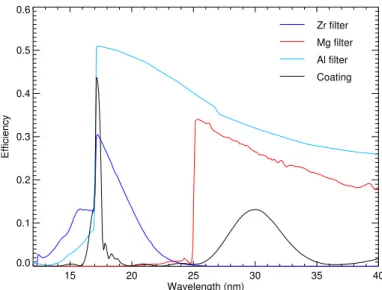
combina-tion of a multi-layer coating reflecting two bands with two types of filters isolating one or the other (see Fig. 6). An Al/Zr/Al (52 nm aluminium/96 nm zirconium/52 nm aluminium) filter is used to select the 17.4 nm pass-band and an Al/Mg/Al (80 nm aluminium/322 nm magnesium/80 nm aluminium) filter is used to select the 30.4 nm pass-band. All filters were procured from the Luxel Corporation. The filter wheel holds two filters of each kind for redundancy against pinholes developing during the lifetime of the instrument. The wheel can potentially also be put in an intermediate position in which the beam is blocked by two mutually exclusive filters. Since there is no shutter in FSI, this position is used when not observing to protect the detector from the EUV-induced degradation suffered by previ-ous EUV telescopes (e.g. EIT, Defise et al. 1999;BenMoussa et al. 2013). Aluminium-based interference coatings have been developed for ten years by Laboratoire Charles Fabry (LCF, Palaiseau, France) in order to achieve higher reflectivity and spectral purity as compared to the EUV coatings used in pre-vious missions (Meltchakov et al. 2010). Moreover, dual-band coatings have been proposed and optimised for FSI in order to reflect two emission lines simultaneously (Auchère et al. 2005; Gautier et al. 2008;Hecquet et al. 2009). The FSI coating con-sists of a superposition of two periodic multi-layers separated by 8 The FSI pupil was initially intended to be positioned at the front of the spacecraft heat shield. The FSI baffle (in front of the aluminium fil-ter) was however not allowed to protrude within the heat shield, requir-ing a larger aperture in the latter.
15 20 25 30 35 40 Wavelength (nm) 0.0 0.1 0.2 0.3 0.4 0.5 0.6 Efficiency Zr filter Mg filter Al filter Coating
Fig. 6.Spectral selection in FSI. The multi-layer coating (black curve) reflects two bands centred on 17.4 nm and 30.4 nm. Zirconium (blue curve) and magnesium (red curve) filters are inserted in the beam near the focal plane to select one or the other. The entrance aluminium filter (light blue curve) transmits both bands. Data are from samples of the flight items.
a buffer layer (formula: [SiC/Mo/Al]4/Al/[SiC/Mo/Al]30) which is deposited on the mirror substrate. The first structure of the coating is an Al/Mo/SiC periodic multi-layer with first order centred at 17.4 nm (30 periods of 8.95 nm). An aluminium buffer layer and a second Al/Mo/SiC periodic multi-layer are deposited on top. This second multi-layer is designed to have its first order centred at 30.4 nm (4 periods of 16.5 nm). The outermost SiC layer is thick enough to guarantee temporal stability so that no additional capping layer is needed. The thickness of the buffer layer is optimised in order to achieve the desired shape of the two Bragg peaks and to create extinctions at undesired wave-lengths (Hecquet et al. 2009;Meltchakov et al. 2011,2013). This enables a spectral purity to be achieved which is comparable to that given by single band coatings in a two-mirror telescope. Ageing, thermal cycling, and exposure to proton radiation have proved these Al-based dual-band coatings to be robust against the Solar Orbiter environment (Delmotte et al. 2013). The result-ing pass-bands of FSI are shown in Fig.23.
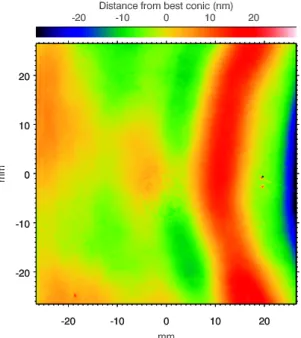
Three mirror substrates (FSI1 to FSI3) have been made in Homosil 101, a quartz from the HTM company (formerly Heraeus). These have been hand polished to a sphere and then ion-beam aspherized off-axis by LCF. The measured osculating radii, corrected by the expected 0.128 mm increase due to the stress induced by the coating (the product stress by thickness was estimated to be 280 Pa.m), were 924.95 ± 0.04 mm, well within the specified 925.00 ± 0.3 mm. The effective focal length of the system is 462.5 mm. After coating, the figure errors of the flight model (FSI2) compared to the best conic surface (corre-sponding to an off-axis distance of 68.89 mm used for alignment) are 50 nm peak-to-valley and 7.2 nm rms (Fig.7). Given the size and position of the pupil, each field is imaged using 1% of the mirror’s useful area. Therefore, figuring errors on spatial scales greater than the pupil size produce distortions at the focal plane and not degradation of the image quality. Root mean square spot radii are smaller than one pixel across the whole detector. The slope errors do not exceed 5.4 µrad, which corresponds to the maximum specified distortion of 0.5 pixel at the focal plane. The roughness was measured with a ZYGO5500 over spatial
Fig. 7.Figuring errors of the flight model of FSI measured after coating compared to the conic minimising the rms deviations.
frequencies ranging from a few mm−1 to 500 mm−1. The rms averaged over 14 zones ranges from 0.13 nm for FSI3 to 0.18 nm for FSI2. The roughness at the interfaces of the multi-layer coat-ing is 0.5 nm (Meltchakov et al. 2013).
The coated and mounted mirror is shown in Fig. 8. The combination of a square detector with a small pupil results in an almost square (53 mm × 53 mm) useful area. The substrate was therefore made square (66 mm × 66 mm), which represents a 35% mass reduction compared to the equivalent circular mirror (93 mm diameter). Additional mass reduction has been achieved (about 50%, down to 103 g) by hollowing the back side.
The small footprint of each field on the optics implies that non-uniformities of the efficiencies translate into local intensity variations at the focal plane. This is equivalent to the pupil of the human eye scanning the lenses of a pair of spectacles. The effect is most pronounced for the focal filters on which the beam foot-print is the smallest. This implies that the supporting mesh grid of the focal filter (and to a lesser extent that of the front filter) can potentially produce a stronger modulation in the images than in other EUV imagers. However, as shown inAuchère et al.(2011), the grid modulation is effectively suppressed if one grid period is equal to an integer multiple of the pupil footprint on the focal filter. The grid mesh is thus hexagonal, as the entrance pupil is, with a distance between hexagon centres of 0.4 mm, that is one-third of the beam footprint of 1.2 mm. The grid rods are 0.04 mm in width, resulting in a uniform geometrical transmission of 0.81%. The focal filters were screened for local defects. The inci-dence angles on the mirror vary between 88.8◦ and 86.3◦. This has negligible impact on the uniformity of the spectral response of the multi-layer coating across the mirror. Thickness variations of the coating produce a 0.1 nm shift of the pass-bands towards the long wavelengths from the centre to the corners of the FOV.
Following the descope of the 30.4 mm channel of Metis, FSI became the only instrument on Solar Orbiter able to explore the extended corona in the EUV up to 10 solar radii, an as yet largely unexplored territory. The FSI was however not originally designed to be able to observe up to these heights. Stray light in EUV imagers can dominate the signal at large angles from
Fig. 8.FSI mirror coated and bonded on its mount.
the solar limb (e.g.Auchère & Artzner 2004) due to a combi-nation of diffraction by the entrance mesh grid and scattering off the optical surfaces. Late in the development it was there-fore decided that the capability of blocking direct solar disc light would be added by adapting a knife-edge occulting disc on the door mechanism in front of the entrance filter. The computed integrated intensity in the shadow cast on the mirror is 6 × 10⁻³ that of the solar disc at 30.4 nm and 4 × 10⁻³of the solar disc at 17.4 nm. It is therefore expected that the stray-light levels will be decreased by the same factors compared to previous, unocculted EUV imaging telescopes, although performance at the working wavelength could not be verified due to the very low expected scattering levels. With a vignetting cutoff at 0.777◦, the occult-ing disc is designed to be used at distances from the Sun larger than 0.34 AU, that is, during the remote sensing windows nom-inally centred on the highest solar latitude points of the orbits. At shorter distances, the stray-light level is expected to be suf-ficiently low in the whole FOV to operate without the occulting disc. The vignetting function increases to 0.49 at the edge and 0.75 in the corners of the FOV. The cutoff corresponds to vary-ing distances to the solar limb along the orbit. The FSI door was qualified for 200 open-close operations, which allows for several FSI coronagraphic campaigns per orbit throughout the mission lifetime. The occulting disc will also be used to characterise the stray light by comparison with regular data.
3.2. High Resolution Imagers
The two HRI units share a similar two-mirror optical design (Fig. 5). The HRILya channel (Schühle et al. 2011) is an off-axis Gregory telescope, and the HRIEUV channel (Halain et al.
2015) is an off-axis Cassegrain telescope optimised in length and width. The entrance pupils are located at the front section of dedicated entrance baffles and have a diameter of 47.4 mm for the HRIEUVand 30 mm diameter for the HRILya.
The Gregory design of the HRILya channel allows the use of a field stop in the light path which, combined with inter-nal baffle walls, strongly limits the stray light from out of the FOV. The HRIEUV channel is made of a Cassegrain telescope which allows for better mirror positioning tolerancing but has less stray-light reduction capabilities (given the absence of an intermediate focus). The optical prescription of the two HRI channels is given in Table2.
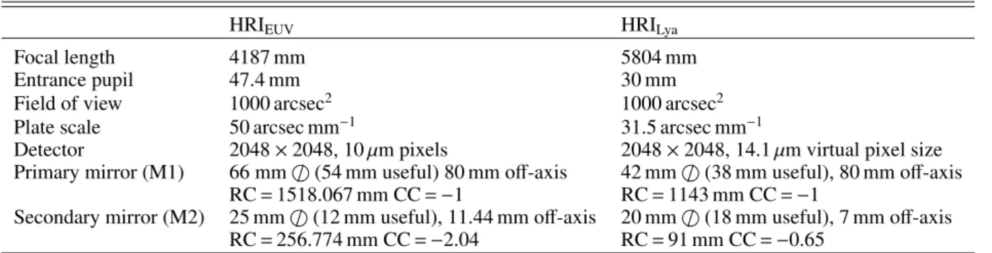
Table 2. Optical design parameters of the HRIEUVand HRILyachannels.
HRIEUV HRILya
Focal length 4187 mm 5804 mm
Entrance pupil 47.4 mm 30 mm
Field of view 1000 arcsec2 1000 arcsec2
Plate scale 50 arcsec mm−1 31.5 arcsec mm−1
Detector 2048 × 2048, 10 µm pixels 2048 × 2048, 14.1 µm virtual pixel size
Primary mirror (M1) 66 mm / (54 mm useful) 80 mm off-axis 42 mm / (38 mm useful), 80 mm off-axis
RC= 1518.067 mm CC = −1 RC= 1143 mm CC = −1
Secondary mirror (M2) 25 mm / (12 mm useful), 11.44 mm off-axis 20 mm / (18 mm useful), 7 mm off-axis
RC= 256.774 mm CC = −2.04 RC= 91 mm CC = −0.65
Notes. Here, RC is the radius of curvature and CC is the conic constant.
Fig. 9.Filter wheel of FSI integrated on the OBS.
The EUV multi-layer coatings of the mirrors are specifi-cally optimised to provide the optimal spectral pass-bands. Their design takes into account the angle of incidence on the mirrors, the variations of which are small enough so that no compensation is needed. Aluminium-based EUV interference coatings have been developed specifically for HRIEUVby LCF. Identical coat-ings have been deposited on both primary and secondary mir-rors. The variations of the angle of incidence between primary and secondary and on each mirror are small enough so that no compensation in period thickness is needed. Periodic Al/Mo/SiC multi-layer coating with first order centred at 17.4 nm has been specifically optimised to provide high efficiency and desired spectral pass-bands. This consists of 30 periods with 8.86 nm period thickness. A 3 nm SiC capping layer was deposited on top in order to improve temporal stability. Aging, thermal cycling, and exposure to proton radiation have proved these periodic Al/Mo/SiC multi-layer coatings to be robust against the Solar Orbiter environment (Delmotte et al. 2013). These HRIEUV pass-band filters were adapted to the wavelengths with respect to the out-of-band suppression and the spectral purity of the pass-band. In Fig.10we show the figuring errors of the flight model of the
Fig. 10.Figuring errors of the flight model of the HRIEUVprimary mir-ror measured after coating compared to the conic minimising the rms deviations. Ringing is an artefact on the measurement setup.
HRIEUVprimary mirror measured after coating compared to the conic minimising the rms deviations.
For the HRIEUVchannel, one aluminium foil filter is inserted between the entrance aperture (entrance pupil) and the primary mirror to provide protection against excessive heat input on the mirror and efficient rejection of the visible light. This HRIEUV entrance filter is a standard filter from Luxel Corporation sup-ported by a nickel mesh grid of 20 lines per inch (lpi) reinforced with a rib structure dividing the filter area over quadrants to improve thermal conductivity and mechanical resistance. A fil-ter wheel with four filfil-ter slots is located at the exit pupil. These four slots each contain two 150 nm aluminium filters (nominal and redundant) from Luxel Corporation, with a 20 lpi nickel grid support, one open slot (no filter), and one occulting slot. The HRI filter wheel, as in the FSI one, is qualified for a million opera-tions. Similarly to the FSI channel, the HRIEUV front and rear EUV filters avoid contamination with visible light.
Fig. 11.Filter wheel of HRI integrated on the OBS.
The HRILya mirrors use Al/MgF2 (aluminium/magnesium fluoride) coatings providing a reflectivity at 121.6 nm of over 86%. A broad-band interference filter (Type 122 NB-40D of Pel-ham Research Optical LLC) is used at the entrance of the tele-scope to isolate the spectral line at 121.6 nm and reject visible and infrared light as well as EUV and X-rays to protect the mir-ror coatings. A narrow-band filter (Type 122 XN-2D of Acton Research Co.) is placed in front of the detector to further isolate the Lyman-α line and achieve the spectral purity. The combina-tion with a solar-blind detector yields a spectral purity higher than 90% for Lyman-α in the quiet Sun regions. It is tolerant to spectral shifts potentially caused by thermal effects. The magne-sium fluoride substrate material of the filters is sufficiently radi-ation hard so as to provide protection against the thermal heat load with minimal degradation during the mission.
4. Mechanical and thermal design
The EUI is a compact instrument based on a passive thermo-mechanical design meaning that there is no active thermal con-trol, but there is passive detector cooling. To avoid contamination which would degrade the instrument response, the EUV sensi-tive detectors of the EUI instrument must however never be the coldest parts of EUI, and in particular its focal plane assemblies (FPAs). In nominal flight conditions, this is ensured by a well-designed FPA, including a “cold cup” that is slightly colder than the detectors to trap contaminants, and by the presence of heaters for annealing and evaporating condensate accumulated on the surface of the detectors. The instrument contains one nominal heater per detector to allow in-flight bake-out (annealing) and a thermal sensor, as part of the detector packaging. When a heater is in use, the corresponding camera electronics are pow-ered off. These heaters will be used sequentially (not together) and controlled by the CEB following a configurable duty-cycle to ensure the temperature of the detectors does not exceed the maximum non-operating (NOP) temperature. These decontami-nation/annealing heaters are 84.3 Ω each, which at 28 V is 9.3 W per camera with a separate control on each. Because the heaters
use the spacecraft 28 V power, the heat output may vary as the voltage varies.
Before nominal flight conditions, that is, just after spacecraft launch, the instrument will not be powered on for possibly sev-eral hours. To limit the temperature drop of the detectors dur-ing ventdur-ing of the instrument and spacecraft out-gassdur-ing, it is therefore planned to heat the three EUI detectors via a second set of spacecraft-controlled “post-launch” heaters controlled by a thermostat and located on the path between each detector and the two cold element (CE) interfaces (see Figs.3 and16). As soon as possible after launch, these heaters are powered by the spacecraft and remain on as long as possible until commission-ing. These post-launch heaters are three series of 15Ω heaters totalling 17.4 W for the EUI OBS.
4.1. Common Electronics Box
The CEB is radiatively and conductively coupled with the space-craft structure (Fig.3). The CEB housing is made of aluminium alloy, has a volume of approximately 0.007 m3, and contains four printed circuit boards (PCBs: a Compression Board, a Proces-sor Board, a power supply board, and an auxiliary board) that are mechanically and thermally coupled with the CEB housing. The functions of the four main boards of the CEB are described below in Sect.5. The CEB box (Fig.2) has a base plate with six M6 screws for attachment to the spacecraft, and a coat-ing of Aeroglaze Z306 which was chosen for its thermal and reflectance properties. The CEB has nine connectors for the EUI internal harness (data, control and power transfer from CEB to OBS) and four connectors for the spacecraft harness (nominal and redundant power and data interfaces).
4.2. Optical Box
The OBS unit structural housing is composed of sand-wich panels (CFRP – Carbon Fibre Reinforced Polymer – facesheets/aluminium honeycomb core) to support the optical elements with the required stiffness and thermal stability while achieving a low mass. The EUI design has been adapted to the mass, volume, and thermal constraints imposed by the space-craft. The OBS unit is supported by three titanium A-shape mounts providing thermal decoupling and an isostatic mechan-ical interface with the spacecraft mounting panel. The main bench is a panel of 30 mm in thickness with reinforced honey-comb at the interface with the three mounts. The back panel is 20 mm thick and holds the two primary mirrors of the HRI chan-nels. The other OBS panels (internal walls between telescopes, lateral and front panels) are 10 mm thick, but only contribute to the OBS unit structural stiffness. Under the OBS unit, the har-ness from the electrical subsystems (camera and mechanisms) is routed toward a connector panel at the rear side.
All optical subsystems, either primary mirror or secondary mirror, filter wheel, or FPA, have their separate interfaces. This arrangement allows for clearly defined interfaces with a mini-mum in thermo-elastic deformation of each channel, providing, in particular, mirror inter-distance and telescope co-alignment stability. Internal baffles made of CFRP layers are also imple-mented within the HRI telescopes to limit potential stray light from the entrance to the detectors. A top cover (10 mm thick) provides additional torsional and bending stiffness to the overall structure.
In contrast to the CEB, the OBS is a thermally insulated unit (Fig.3) that remains in an acceptable temperature range in hot
and cold flight environments. It has a low conductive link to the platform (low conductance mounts) and radiative insulation (two-layer MLI), taking advantage of the optical bench with a low coefficient of thermal expansion (CTE) on which the three EUI telescopes are mounted and co-aligned. The OBS is an inter-nally mounted instrument within the spacecraft cavity.
The thermal design of the EUI OBS unit takes into account the specific thermal environment of the Solar Orbiter mis-sion and in particular of the 13 solar constants solar heat flux (17.5 kW m−2) at perihelion. The front of the OBS unit (doors and entrance baffles) is consequently thermally decoupled from the rest of the OBS unit to limit thermo-elastic deformation and ensure optical performance over the operational temperature range of −20◦C to+50◦C. It is however thermally coupled with the spacecraft by two redundant heat pipes to evacuate the solar and infrared heat absorbed by the entrance baffles and filters (see Fig.3).
Being directly exposed to the highly varying solar flux, the ultra-thin EUV front filters are subject to large variations and spatial gradients. An optimised custom frame was developed that divides the exposed area into smaller cells without significantly altering the optical throughput. In this way, the temperature gra-dient could be reduced by more than a factor of two. The EUI detectors must be cooled to a temperature lower than −40◦C (target −60◦C) with a stability of ±5◦C. The OBS unit is also therefore thermally coupled to some spacecraft radiators through dedicated thermal straps, allowing the transfer of dissipated heat by the detectors (through a cold element (CE) interface) and by the camera electronics boards (medium element (ME) interface); see Fig.3. Because of spacecraft constraints, the two HRIs share a common CE and common ME interface with the spacecraft, while the FSI has its own CE and ME interfaces.
4.3. Filter wheels
The EUI employs two filter wheels, one in FSI and the other one in HRIEUV. Both have been developed by IAS with sup-port from the Centre National d’Etudes Spatiales. The FSI filter wheel (Fig.9) is used for wavelength selection and is therefore a critical component that has been qualified for approximately 1 million operations (quarter turns), corresponding to a worst case of continuous observations at two wavelengths at 10 min cadence through the end of extended mission phase, and on-ground operations, with a safety factor of 1.2. The HRIEUVfilter wheel (Fig.11) on the other hand provides redundancy for the focal filter and a masking position to protect the detector against radiation-induced degradation and was designed for 400 oper-ations. Due to mass and volume constraints, mechanisms are of the paddle wheel type. The mass distribution of the di ffer-ent elemffer-ents was precision balanced in order to avoid the need for a launch-lock system. The design also minimises the thermo-elastic stresses with the optical bench. The filter wheels are con-nected to the rotor of their respective motor via elastic couplings without gear reduction stages. The axis of the FSI wheel is sup-ported by two ball bearings dry-lubricated with MoS2. Due to its light weight, the HRI wheel is directly supported by the bear-ing of its motor. Both motors are custom dual-windbear-ing steppers from Phytron GmbH. The temperatures of the motors are con-trolled by thermal sensors in the motors driven by the CEB.
Cancellation of the grid modulation pattern in FSI (see Sect. 3.1 andAuchère et al. 2011) requires positioning of the filters to within ±0.5 mm along the beam and a rotational accu-racy of ±1◦. This latter requirement was a major design driver. The stepper motor has 200 steps, and additional margin is
obtained using micro-stepping control. The whole mechanism was aligned to bring its reference position to within ±0.17◦of its nominal orientation with respect to the optical axis (8.66◦). The lifetime test has demonstrated the repeatability of the behaviour. The knowledge of the FSI filter wheel position is ensured by a combination of four opto-isolators.
5. Electronics
All the EUI electronics are grouped in the CEB (Sect. 5.2), except for the so-called Front End Electronics (FEE) which are associated with the sensors in the three telescope cameras (Sect.5.1).
5.1. Cameras and sensors
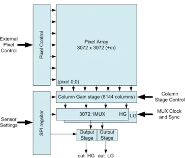
Each telescope has its own dedicated camera (also called Focal Plane Assembly) mounted on the OBS main bench. The EUI cameras are based on large-format 3072 × 3072 10 µm pitch CMOS-APS detectors, allowing shutterless operation, greater radiation tolerance (no charge transfer), low power consump-tion, high operational temperature (>−60◦C), high speed, high dynamic range, and non-destructive readout. The devices consist of two stitching blocks of 3072 × 1536 pixels and are based on the architecture shown in Fig. 12. In order to reach ambitious goals for both the read noise and the dynamic range, a dual-gain pixel design was developed: each pixel outputs both a high-gain signal, with low read noise and a low saturation level, and a low-gain signal, with a high saturation level but larger read-noise. The sensor is controlled through 32 register settings that con-trol, among others, gain factors, clipping values, and offset val-ues. The detectors have a full well of the order of 120k electrons (device dependent), which is the same for both gains (defined by saturation of the pinned photodiode), but the high gain is ADC clipped. The theoretical ratio in gain between the high and low gain channels with default electronic settings is 22.3. In practise, this ratio is device dependent and configurable in flight.
The EUI detector package is designed to take into account the thermo-mechanical constraints of the camera; see Fig. 13. It is made of aluminium nitride (AlN) providing sufficient ther-mal conductivity and similar CTE to that of the sensor and is supported by three Ti blades providing thermal decoupling from the mounting interface. A copper strap is used to provide the thermal link to the spacecraft radiators (Fig.14). The electrical connection to the FEE is achieved through a flexible PCB. The temperature is monitored with a thermal sensor integrated into the detector. For decontamination purposes, the detector is also equipped with a heater allowing heating and in-flight bake-out sequences to be performed if required.
The HRILya camera detector is a solar-blind, intensified, CMOS active pixel sensor (I-APS). The camera intensifier is a closed unit held under vacuum by a MgF2 entrance window and a fibre optic output window. The output window is glued to a fibre-optic taper, which is coupled with the image sensor by direct contact with the active area of the sensor and mechanically stabilised by epoxy gluing with an Invar frame to the sensor package. The intensifier also has a blocking filter such that it transmits no visible light and only light produced by electrons from the micro-channel plate (MCP) will be detected by the CMOS sensor.
The intensifier of HRILya was built by ProxiVision GmbH (Germany) and shares the same design as the Metis UV detec-tor (Schühle et al. 2018): a closed tube with a UV-grade magne-sium fluoride entrance window and a single MCP that transforms
Fig. 12.EUI 3072 × 3072 detector architecture block diagram.
Fig. 13. EUI flight detector with package and connector via flexible PCB.
Fig. 14.HRIEUVcamera flight model. See also Fig.16for a schematic layout.
the incoming UV photons into electrons which are accelerated against a phosphorous screen. The focal plane of the camera coincides with the entrance face of the MCP where the photo-cathode is deposited. The photophoto-cathode of potassium bromide (KBr) provides high sensitivity at 121.6 nm and suppresses the response at longer wavelengths. The photo-electrons amplified by the MCP are accelerated by a high voltage (of nominally 6 kV) onto a P46 phosphorous screen. A regulated high voltage unit (HVU) provides the voltages for the MCP and the phos-phorous screen. The sensitive aperture of the intensifier tube is 40 mm in diameter, and a square image of 28.3 mm × 28.3 mm on the phosphorous screen is transferred by a fibre optic face
Fig. 15.HRILyacamera with the APS sensor mounted in the middle, the Front End Electronics (FEE) on the right hand side, and the intensifier on the left hand side. See also Fig.16for a schematic layout.
plate and a fibre optic taper with a de-magnification factor of 1.41 to the actual size of the CMOS-APS sensor. In this way, the image size is reduced to cover only a 2048 × 2048 sub-area on the 3072 × 3072 10 µm pixel sensor. This provides an image scale of the telescope of 1 arcsec per two pixels. Due to the mechanical mounting of the fibre optic image transfer, the useful size of the taper on the sensor is slightly smaller than 2048 pixels (actual size is 1984 × 1984 pixels), corresponding to a FOV of 992 arcsec × 992 arcsec. The intensifier assembly has the advantage of having a very low sensitivity to radiation above 150 nm (because of the photocathode response) and below 115 nm (because of the MgF2 window), thus greatly helping to isolate the wavelength of interest. The intensifier is mounted with a ceramic ring via four blades to the camera housing, while the APS sensor is hard-glued to it and connected only by thermal straps to the CE interface (Fig.15).
The HRIEUVand FSI channels share a common FPA design, as shown in Fig.16(top). A cold cup is located in front of the detector and is linked to the same cooling path as the detector in such a way as to ensure the detector is not the coldest part of the instrument to reduce condensation of molecular contami-nation on the detector. The cameras also include two redundant UV LEDs (at 255 nm) for ground tests and in-flight relative cali-bration mounted in such a way that they obliquely illuminate the whole detector.
The HRILyachannel camera uses the same FPA mechanical design as the HRIEUV and FSI channels but it carries the inten-sifier unit (see bottom of Fig.16). The HRILyacamera does not have a cold cup, as the detector is directly glued to the intensifier, and its detector is maintained in position through the intensifier fixation to the structure.
The intensifier tube requires regulated high voltages up to 1 kV and 6 kV maximum for the MCP and the phosphorous screen. An external HVU switches an isolated secondary power to obtain these voltages up to a maximum of 7 kV. Differential analogue lines from the CEB control the two high voltage (HV) outputs. Differential analogue outputs are fed back to the CEB to monitor the HVU outputs. The HVU provides HV panel con-nectors on the backside of the housing. Pigtail cables for the screen and the MCP are soldered on the intensifier side and plugged to the panel connectors on the HVU. The low voltage (LV) electronics part is separated on the PCB9from the HV parts
with appropriate spacing (assuming a maximum permitted DC 9 Printed Circuit Board.
Fig. 16. Camera layout for FSI and HRIEUV cameras (top) and for HRILya camera (bottom). Photons enter the camera from the left and reach the CMOS APS from where the signal is read-out to the FEE and ultimately to the CEB (right). The HRILyacamera (bottom) has an additional HVU and intensifier. In brown, the Cold Finger (CF) thermal strap and ME thermal strap are shown.
voltage of 600 V mm−1across surfaces) to prevent discharges or a propagation of HV to the LV parts. The HV circuitry is put on the top layer of the PCB and no traces from the LV side are routed within or below this area. High voltage tracks are routed with rounded edges to prevent strong electrical fields on edges. Primary and secondary ground on the HV converter are com-pletely separated on the PCB and connected together only at a single ground point at the secondary output side of the HV trans-former. This single ground point is routed to the Structure GND (ground) via a (removable) ground stud connection. The outputs for screen and MCP are floating at the connected intensifier side and grounded at the converter output. The HVU is mounted sep-arately from the camera inside the HRILyachannel on the optical bench.
5.2. Common Electronics Box
The CEB electronics consist of four PCBs: the Processor Board, the Compression Board, the Auxiliary Board, and the Power Board. These are all plugged into a motherboard (which has no components other than the connectors for the other boards). The interfaces to the Solar Orbiter Spacecraft are prime and redun-dant 28 V power connections, prime and redunredun-dant SpaceWire connections and high-power pulse command connections for
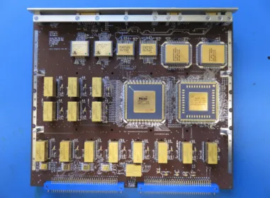
Fig. 17.Processor Board in the EUI CEB. At the bottom of the board there are gigabytes of SDRAM for the One-Hour-Queue (OHQ) seen as eight blocks, and at the very bottom in the middle is the flash memory. The Spacecraft Output Buffer (SOB) is located in the middle left as six blocks. The Processor Board FPGA is at the centre with the UT699 CPU to the right. The two components to the top left are the MRAM. The next four components (two small, two large) on the top right are the CPU SRAM.
commanding power on and power off. The SpaceWire links allow telecommands to be sent to the CEB and telemetry (house-keeping, events, and science data) to be sent from the CEB. Other CEB interfaces connect with the OBS to provide power to the cameras, heaters, and mechanisms to allow data to and from the cameras and output from thermistors and thermocouples on the OBS.
5.2.1. The Processor Board
The Processor Board contains the CEB’s Central Processing Unit (CPU), a Cobham-Gaisler single UT699 LEON3 SPARC Application-Specific Integrated Circuit (ASIC) which also has four SpaceWire interfaces, two of which are used. The CPU is connected to some write-disabled Magnetoresistive Random-Access Memory (MRAM) and some read/write MRAM from which to boot the Basic “Boot software” and Oper “Applica-tion software”, some Static Random-Access Memory (SRAM) as main processor memory and to an Actel Field-Programmable Gate Array (FPGA). This Processor Board FPGA provides an interface to gigabytes of Synchronous Dynamic Random-Access Memory (SDRAM) for immediate and longer-term storage of science data (the One Hour Queue (OHQ) and Spacecraft Out-put Buffer (SOB)), the usage of which is described in Sect.6.3. The FPGA also provides an interface to flash memory for non-volatile storage of calibration data as well as interfaces to the other FPGAs of the CEB on the other boards. Figure17shows the Processor Board.
5.2.2. The Compression Board
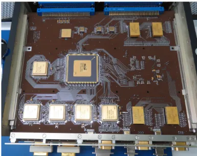
The Compression Board consists of an FPGA which has some fast SRAM for storage of pixel-processing maps, a WICOM compression ASIC with SDRAM to perform fast wavelet data compression, and the interfaces for the incoming data from the cameras. Figure18shows the Compression Board. As data
Fig. 18.EUI CEB Compression Board. The Compression Board FPGA is the large integrated circuit near the centre. The block on the middle left together with the first three of the bottom row are the compression SRAM. The WICOM is the fourth block of the bottom row. On the top right and bottom right there are four SDRAMs for the WICOM.
arrives from a camera, various stages of on-the-fly image cessing can be enabled. The aim of this onboard image pro-cessing is to enhance the effectiveness of data compression (discontinuities produced by detector features would degrade the ability of the compression). These stages operate on an image-by-image basis and are: pixel and global gain correction, per-pixel and global offset correction, bad pixel correction, cosmic ray filter, rebinning, thumbnail and histogram generation, and recoding (Nicula et al. 2005).
As the detectors have two different gains in dual-gain mode, strongly exposed pixels (bright) will report a low gain value while weakly exposed pixels (dark) will report a high gain value. The images arriving at the compression board will thus con-tain a mixture of pixel values of both of the gains. As a result, the FPGA is required to apply a global gain and offset correc-tion (which are simple adjustable constants) and a per-pixel gain and offset correction which are pre-loaded in the compression SRAM as a pair of maps, one for each of the two gains.
The SRAM maps also contain maps of bad pixels. A pixel is labelled as “bad” when its sensitivy or dark current deviates sig-nificantly from that of its neighbours. The value of a bad pixel is replaced as it arrives at the FPGA with the value of the last good pixel in the image. If the bad pixel is the first pixel in a line, then the value of the first pixel in the previous line is used, and for the first pixel of the first line, an adjustable constant is used. The cos-mic ray filter identifies significant point-like outliers originating from both cosmic rays and solar energetic particles, and replaces them with a local 3 × 3 median-like value which is calculated not by processing the image as a whole but by buffering recent lines and working as the pixels arrive.
For very high compression ratios (lower bits per pixel), it is beneficial to bin the image before compression. This can be enabled in the FPGA with a choice of 2 × 2 and 4 × 4 binning. This reduces the effective spatial resolution but provides an over-all better image quality for applications when the ultimate spa-tial resolution is not required. As the pixels arrive, the FPGA can also calculate the image histogram and a highly binned thumb-nail before the image is sent for compression, after which the
software can no longer “see” the original image. The histograms are intended to retain minimal information on images that cannot be brought to the ground.
The final optional stage of pixel processing is recoding in which each incoming pixel is scaled between user-defined low and high values and the integer square root (8 bit) is calculated.
Once the pixel processing has made the image suitable for compression, if enabled, the image is sent to the WICOM for compression. An ASIC such as the WICOM is required as the compression must be performed very quickly (half a second) during the time that the next image is being integrated on the detector (which could be a half-second exposure). As many images are taken and only the relevant ones (e.g. with solar activ-ity) are selected, the compression speed and power efficiency of an ASIC solution is essential for the speed and power constraints of EUI.
5.2.3. High-Speed Links
The CEB communicates with the cameras by pairs of High-Speed Links (HSL), one pair for each camera, which are based on SpaceWire but simplified with a different protocol. Two HSLs were used per camera to enhance the speed of data transfer. The efficient design allows simple short commands to be sent from the CEB to the cameras at a slower rate, whereas the responses to commands and images from the cameras to the CEB are at a fast configurable rate to deal with data volume.
5.2.4. The WICOM
The WICOM ASIC was developed for the PLEIADES mis-sion by EADS-Astrium, now Airbus. It uses a JPEG2000-like wavelet compression called MRCPB which is optimised for use in space missions and can perform lossless or lossy com-pression at a wide range of bit rates. The WICOM uses ded-icated SDRAM for temporary storage. The EUI benefits from WICOM versatility including a compression mode where a large image of 3072 × 3072 (or square subfields thereof, as for the HRI 2048 × 2048 images) is compressed globally at very high compression ratio (less than 0.1 bits per pixel with the aid of binning and recoding), automatically allocating the few bits to describe the most important local events in the solar disc image.
5.2.5. The Auxiliary Board
The Auxiliary Board contains an FPGA which drives the step-per motors of the filter wheels and doors, gathers analogue and digital parameters from the CEB, and controls and monitors the electronic current trips and the power switching (heater control, door launch locks and camera power). Figure19shows a photo-graph of the auxiliary board.
5.3. The Power Board
The Power Board supplies isolated secondary power for the CEB and the three cameras. It is made up of four switching DC/DC iso-lating Power Supply Units (PSUs), one for the CEB and one for each of the cameras. This design allows the number of switches to be minimised by turning the PSUs of the three cameras on and off at their inputs rather than at their more numerous outputs. The Power Board interfaces to the spacecraft prime and redundant power buses. Figure20shows a photo of the Power Board.
Fig. 19. EUI CEB auxiliary board. The AUX board FPGA is at the centre. The bottom third of the board contains the motor drive circuitry. Housekeeping is digitized in the top part of the board.
Fig. 20.EUI CEB power supply unit. The top left are the voltage reg-ulators for internal supplies, the top right is the housekeeping filtering and conditioning, the bottom left is the CEB PSU, and the bottom right are the camera PSUs.
The electronic parts are qualified for space use and are suit-able for the high radiation environment outside the Earth’s mag-netosphere and near the Sun. Some of the memories have to be continually checked and corrected for errors (“scrubbed”). This is done for some devices by the device itself, for some by an FPGA, and for others by the software. It is expected that the flash memory will develop bad blocks throughout its lifetime, which will be dealt with by the software.
6. Flight software 6.1. Software overview
The EUI flight software runs on the Cobham-Gaisler LEON SPARC10 processor of the CEB. It uses the Gaisler-modified
10 Scalable Processor Architecture.
RTEMS11-4.10.2, a well-written, robust, and well-maintained real-time open source operating system. Software development is performed on Linux with GNU tools. With the source code available for RTEMS, the compilation tools and Linux, this offers the highest level of maintainability for a long mission.
The software consists of two separate subsystems. Basic (boot) software starts on boot-up and is as simple as possible yet able to load and dump memory and perform health monitor-ing and reportmonitor-ing. This code is stored in read-only non-volatile memory. In contrast, the Oper (application) code supports full functionality and is stored separately in re-writable non-volatile memory so that it may be patched after launch.
Compliance to ECSS (European Cooperation for Space Stan-dardisation) and MISRA (Motor Industry Software Reliability Association) was strictly maintained during development with very few exceptions. Thus, an extensive test programme and defensive programming makes the software very robust and maintainable as is necessary for a space mission.
RTEMS is used as the interface to the CPU which also con-tains the SpaceWire interfaces. It was modified only slightly to meet the necessary functionality. RTEMS provides the sched-uler, interrupt handling, tasks (threads), semaphores, and mes-sage queues that are required by the software in a manner which is familiar to the programmer.
The software is written in a highly modular fashion with modules well separated and tasks communicating with each other using RTEMS message queues for good synchronisation and safety.
6.2. Basic software functionality
Incoming telecommands are received by the Gaisler RTEMS SpaceWire driver and interrupts are generated. Two telecom-mand tasks process these telecomtelecom-mands (one task for each of the redundant interfaces). The required checks are performed on the telecommands and they are passed on to the appropriate modules of the software to be checked and processed further. If requested in the telecommand, verification acceptance and com-pletion telemetry packets are generated and any errors produce verification failure packets.
Approximately 2000 housekeeping parameters are sent to the ground periodically in nine different housekeeping teleme-try packets to report the state and health of the instrument. This is handled by the housekeeping module with its task. Memory management is handled by its module and task with the abil-ity to load, dump, and checksum all memories where possi-ble. Memory scrubbing and watchdog management is performed by another module with its task. The memories that are to be scrubbed by software are continuously read and checked, and single bit errors are corrected. If multiple bit errors are found, either an error will be sent or the system will be rebooted depending on the affected memory. Event reporting is performed by its module to allow the ground and spacecraft to keep track of normal progress, warnings, and errors. The testcommand mod-ule simply provides the ability to respond to a test command to check connectivity. Another module, timesync, updates and reads the clock in the CEB’s Processor Board FPGA and times-tamps packets as required. The functionality described above is common to Basic and Oper.