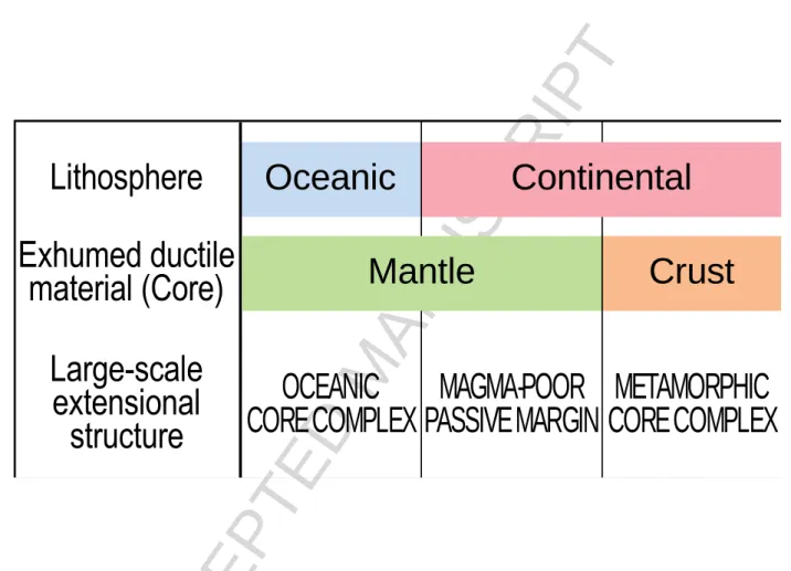
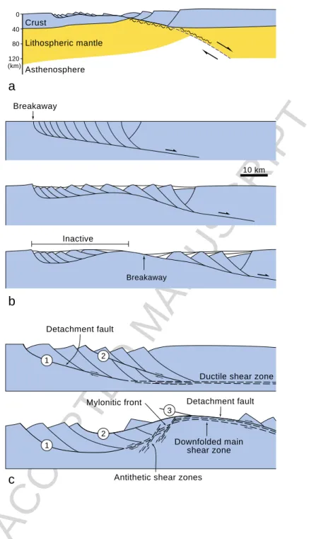
Crustal versus mantle core complexes
Texte intégral
Figure

Documents relatifs
“If most authors admit that the continental crust of the North Pyrenean Zone suffered an extension from the late Aptian onwards, many points are still poorly understood, especially [
The ages of the HT-LP metamorphism obtained on metasediments from the paleomargin give a bracket between 97 and 85 Ma, that is, Cenomanian to upper Coniacian –lower Santonian
* Given the level of uncertainty regarding tower life expectancy, due to the underlying uncertainty in the distributions of both corrosion rate and failure point, a strategy
For power amplifier (PA) systems, digital predistortion has been a popular way to enhance the linearity of the system without sacrificing power efficiency by power
Knowledge-based signal processing (KBSP) is the application of the numerical algorithms of signal processing and the symbolic inference techniques of expert systems
The water within the wood goes toward inside the joints, then stagnates against the metal plate during the warming up of the timber members and produces an endothermic
The aim of this study was to measure the prevalence of CTI and assess factors associated with infection in a sequential sample of undocumented immigrants without health insurance
Graphique 3 • Part des salaires compris entre 1,0 et 1,05 Smic et salaire mensuel net moyen pour les employés et les ouvriers en 2010, pour les principales conventions
