Controlling the Architectures and Optical Properties of
Conjugated Polymer Aggregates and Films
by
Andrew Satrijo
B.Sc. (First Class Honors) Chemistry, Co-op Education Science Simon Fraser University, 2002
Submitted to the Department of Chemistry
in Partial Fulfillment of the Requirements for the Degree of Doctor of Philosophy
at the
Massachusetts Institute of Technology June 2007
© Massachusetts Institute of Technology, 2007. All rights reserved.
Signature of Author: _____________________________________________________ Department of Chemistry May 16, 2007 Certified by: ____________________________________________________________ Timothy M. Swager Thesis Supervisor Accepted by: ___________________________________________________________ Robert W. Field
This doctoral thesis has been examined by a Committee of the Department of Chemistry as follows:
Professor Gregory C. Fu: _________________________________________________ Thesis Committee Chair
Professor Timothy M. Swager: _____________________________________________ Thesis Supervisor
Professor Barbara Imperiali: _______________________________________________ Department of Chemistry
Dedicated to my family,
for their unwavering love and support, and Elizabeth
Controlling the Architectures and Optical Properties of
Conjugated Polymer Aggregates and Films
by
Andrew Satrijo
Submitted to the Department of Chemistry on May 16, 2007 in Partial Fulfillment of the Requirements for the Degree of
Doctor of Philosophy in Chemistry. ABSTRACT
The semiconducting properties of conjugated polymers are finding use in various optoelectronic applications, including chemical sensors and light-emitting diodes. In this thesis, we investigate aggregation in conjugated polymers and how it affects the optical properties of these organic materials.
We discuss how aggregation enhances exciton transport properties in fluorescent polymers, thereby increasing the probability of excitons reaching low-energy sites in the polymer. A consequence of this aggregation-enhanced exciton migration is that low-energy defect sites in a conjugated polymer can dramatically alter the polymer’s fluorescence properties when it is in an aggregated state. In a poly(p-phenylene ethynylene) (PPE) that was previously proposed to form green-emitting excimers, we found that a small concentration of anthryl defects in the polymer emitted green fluorescence that was only noticeable when the polymer was in an aggregated state (otherwise the polymer was fluorescent blue). After elucidating the origin of the green fluorescence, we purposely added more emissive anthryl units into the polymer to enhance the blue-to-green fluorescence color change that accompanied polymer aggregation. Using this anthryl-doped conjugated polymer, we developed aggregation-based chemical sensors that exhibited a visually noticeable fluorescence color change upon addition of poor solvents or biologically relevant, nonquenching, multicationic analytes (e.g., polyamines, neomycin) to the polymer solution.
We also studied the effects of aggregation on the optical properties of a chiral poly(p-phenylene vinylene) (PPV) derivative in solutions and in films. We found that the organizations and functional properties existing in aggregated polymer solutions can be transferred to the film state by controlling the processing conditions. Using the same polymer, we were able to obtain films with different architectures and luminescence properties simply by adjusting the spin-casting solvent and film annealing conditions. Controlling the organizations and functional properties of conjugated polymer films is important in the fabrication of conjugated polymer-based optoelectronic devices.
Thesis Supervisor: Timothy M. Swager
Table of Contents
Title Page ... 1 Signature Page ... 3 Dedication ... 5 Abstract ... 7 Table of Contents ... 9 List of Abbreviations ... 11Lists of Figures, Schemes, and Tables ... 13
Chapter 1. Introduction to Conjugated Polymer Aggregation
... 211.1 Conjugated Polymers ... 22
1.2 Photophysical Processes in Conjugated Polymers ... 23
1.3 Fluorescence Quenching ... 27
1.3.1 Fluorescence Quenching by Analytes ... 27
1.3.2 Other Fluorescence-Quenching Mechanisms ... 29
1.4 Exciton Migration in Aggregated Conjugated Polymers ... 31
1.5 Aggregation Effects in Conjugated Polyelectrolyte-Based Chemical Sensors .... 33
1.6 Nonquenching Analytes and Emissive Defects ... 35
1.7 Conformations of Conjugated Polymers in Solutions and Films ... 36
1.7.1 J-Aggregates and H-Aggregates ... 37
1.7.2 Chiral Orientations and Exciton-Coupled Circular Dichroism Spectroscopy ... 38
1.8 Controlling the Architectures and Properties of Conjugated Polymer Films: Implications for Conjugated Polymer-Based Devices ... 39
1.9 References ... 41
Chapter 2. Enhanced Luminescence from Emissive Defects in
Aggregated Conjugated Polymers
... 452.1 Introduction ... 46
2.2 Results and Discussion ... 49
2.2.1 Preliminary Degradation Studies ... 49
2.2.2 Simulating a Degraded Polymer ... 53
2.2.3 Aggregation Studies ... 66
2.3 Conclusions ... 70
2.4 Experimental Section ... 71
2.5 References ... 78
Chapter 3. Anthryl-Doped Conjugated Polyelectrolytes as
Aggregation-Based Sensors for Nonquenching Multicationic Analytes
933.1 Introduction ... 94
3.2 Results and Discussion ... 98
3.2.1 Synthesis ... 98
3.2.2 Solvent-Induced Aggregation ... 100
3.2.3 Aggregation-Based Sensing of Nonquenching Multicationic Analytes 103 3.3 Conclusions ... 114
3.4 Experimental Section ... 115
3.5 References and Notes ... 119
3.A Appendix ... 123
Chapter 4. Facile Control of Chiral Packing in Poly(p-Phenylene
Vinylene Spin-Cast Films
... 1294.1 Introduction ... 130
4.2 Results and Discussion ... 131
4.2.1 Synthesis ... 131
4.2.2 Aggregation of PPV1 Solutions and Films ... 133
4.2.3 Aggregation of PPV2 Solutions and Films ... 138
4.3 Conclusions ... 140
4.4 Experimental Section ... 141
4.5 References and Notes ... 149
4.A Appendix ... 153
Chapter 5. Probing a Conjugated Polymer’s Transfer of
Organization-Dependent Properties from Solutions to Films
... 1655.1 Introduction ... 166
5.2 Results and Discussion ... 166
5.2.1 Optical Properties of Polymer Films ... 167
5.2.2 Optical Properties of Polymer Solutions... 170
5.2.3 Comparison of Fluorescence Quantum Yields ... 172
5.2.4 Comparison of gabs and glum Values ... 173
5.3 Conclusions ... 175
5.4 Experimental Section ... 176
5.5 References and Notes ... 178
Curriculum Vitae ... 183
List of Abbreviations
ATR–IR attenuated total reflection–infrared spectroscopy BT 2,1,3-benzothiadiazoleCD circular dichroism
CPE conjugated polyelectrolyte
CPL circularly polarized luminescence D low-energy, emissive defect
Δ heat
DCE 1,2-dichloroethane
DMAD dimethyl acetylenedicarboxylate DMF N,N-dimethyl formamide
DMSO dimethyl sulfoxide DNA deoxyribonucleic acid
ECCD exciton-coupled circular dichroism ESI electrospray ionization
EtOH ethanol
FT–ICR–MS Fourier-transform ion cyclotron resonance mass spectrometry GC–MS gas chromatography–mass spectrometry
GPC gel permeation chromatography HOMO highest occupied molecular orbital HRMS high-resolution mass spectrometry
hν photon
LED light-emitting diode
LUMO lowest unoccupied molecular orbital
MBL-PPV poly[5-methoxy-2-(4-sulfobutoxy)-1,4-phenylene vinylene] MeCN acetonitrile
MEH-PPV poly[2-(2’-ethylhexyloxy)-5-methoxy-1,4-phenylene vinylene] MeOH methanol
Mn number-average molecular weight
m.p. melting point
MPS-PPV poly(2-methoxy-5-propyloxy sulfonate phenylene vinylene)
MS mass spectrometry
MV2+ dimethyl viologen m/z mass-to-charge ratio NBS N-bromosuccinimide
NMR nuclear magnetic resonance OD optical density
PA polyacetylene
PAni polyaniline
PDI polydispersity index
PF polyfluorene
PFPB poly[(9,9-bis(6’-N,N,N-trimethylammoniumbromide)hexyl)fluorene-alt-1,4- phenylene]
PhMe toluene
PPE poly(para-phenylene ethynylene) PPV poly(para-phenylene vinylene) PPP poly(para-phenylene) PPy polypyrrole PT polythiophene PTFE polytetrafluoroethylene PVA poly(vinyl alcohol) Q fluorescence quencher QMA quadrupole mass analyzer
rt room temperature
Sn singlet electronic state
TBAF tetrabutylammonium fluoride TFA trifluoroacetic acid
TG–MS thermogravimetric–mass spectrometry TMEDA N,N,N’,N’-tetramethylethylenediamine Tn triplet electronic state
THF tetrahydrofuran UV–vis ultraviolet–visible v vibrational level v:v volume: volume ratio
List of Figures
Figure 1.1 Common examples of π-conjugated polymers. 22
Figure 1.2 Schematic representations of the interacting highest occupied molecular orbitals (HOMO) and lowest unoccupied molecular orbitals (LUMO) in a conjugated system, the valence band and conduction band of a semiconducting polymer, and the corresponding energy gaps, Eg. Each single-headed arrow represents an electron, which
can be excited from the HOMO to the LUMO by the absorption of a photon (hν) having energy greater than Eg.
24
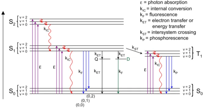
Figure 1.3 State energy diagram of some photophysical processes. Refer to the text for a detailed description.
26
Figure 1.4 Schematic illustration of a molecular wire sensor exhibiting exciton formation, migration, and deactivation by electron transfer or energy transfer between the fluorescent conjugated polymer and a fluorescence-quenching analyte (Q).
28
Figure 1.5 In an unconjugated system of isolated fluorescent molecules, one analyte (Q) can quench the fluorescence from only one molecule.
29
Figure 1.6 Schematic representations of exciton migration in conjugated polymers in a
dilute solution, an aggregated solution, and a solid film. 32 Figure 1.7 State energy diagrams for a J-aggregate, an H-aggregate, and an oblique
orientation of two chromophores. The dashed arrows represent forbidden transitions, and the long, solid arrows represent allowed transitions. The pairs of small arrows represent induced electric dipoles in the interacting chromophores.
37
Figure 1.8 Illustration of the exciton chirality rule, which correlates a) a negative CD
couplet to M-chirality, and b) a positive CD couplet to P-chirality. 38 Figure 1.9 Illustration of spin-casting deposition of a polymer solution to prepare a
uniform film, and fluorescence photographs of a solution (left) and spin-cast film (right) of a poly(p-phenylene vinylene) derivative (PPV1 in Chapters 4 and 5), irradiated with a 365 nm mercury lamp.
40
Figure 2.1 (a) Structure of anti-PPE, (b) normalized absorption and emission spectra of
anti-PPE in chloroform solution (dotted line) and as a spin-cast film (solid line), and (c)
normalized emission spectra of anti-PPE as a function of the absorption optical density (OD) of the film, indicative of its thickness, which was controlled by adjusting the concentration of the spin-casting solution.
48
Figure 2.2 Oxidative degradation of poly(9,9-dialkylfluorene) to produce fluorenone on-chain defects.
Figure 2.3 (a) Fluorescence spectra of an anti-PPE spin-cast film (OD = 0.24), upon photoirradiation with a fluorometer (excitation wavelength λex = 375 nm, bandpass = 2.5
nm) in an ambient air atmosphere. (b) Fluorescence spectra (λex = 375 nm) of anti-PPE
spin-cast films, before (red) and after (blue) the film (OD = 0.23) was irradiated for 3.5 minutes with a UVP Pen Ray mercury lamp (254 nm) in an inert nitrogen (glovebox) atmosphere. Green line: fluorescence spectrum (λex = 375 nm) of a spin-cast film (OD =
0.12) of a sample of anti-PPE that was previously heated to 300 ˚C in an inert helium atmosphere.
51
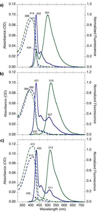
Figure 2.4 Absorption (dashed) and normalized fluorescence (solid) spectra of syn-PPE in chloroform solution (blue) and as a spin-cast film (green). Fluorescence spectra were obtained using an excitation wavelength λex = 375 nm.
54
Figure 2.5 Retro-Diels–Alder reaction in a PPE containing a [2.2.2] bicyclic ring system. 55 Figure 2.6 Proposed degradation product from the photoirradiation or heating of
syn-PPE.
55
Figure 2.7 Absorption (dashed) and normalized fluorescence (solid) spectra of (a) syn-PPE1, (b) syn-PPE9, and (c) thermally degraded syn-PPE in chloroform solution (blue)
and as spin-cast films (green). Fluorescence spectra were obtained using an excitation wavelength λex = 375 nm.
59
Figure 2.8 Normalized absorption spectra of anti-6 (red), syn-6 (blue), and the anthryl monomer, 8 (green), dissolved in chloroform.
61
Figure 2.9 Absorption (dashed) and normalized fluorescence (solid) spectra of syn-PPE9
(blue) and thermally degraded syn-PPE (red) in chloroform solution. Fluorescence spectra were obtained using an excitation wavelength λex = 375 nm. The low-energy
fluorescence spectra of each polymer were obtained by excitation at 459 nm (purple and brown, respectively).
62
Figure 2.10 Absorption (dashed) and normalized fluorescence (solid) spectra of thermally degraded anti-PPE (blue) in chloroform solution. The fluorescence spectrum was obtained using an excitation wavelength λex = 375 nm. The low-energy fluorescence
spectrum (purple) was obtained by excitation at 459 nm.
63
Figure 2.11 GC–MS of dimethyl acetylenedicarboxylate (DMAD), which had an elution
time of 6.70–6.90 min. 64
Figure 2.12 TG–MS of anti-PPE; thermogravimetric analysis (black) was performed with a heating ramp of 5 ˚C/min; MS data shown for m/z 52 (blue), 59 (red), and 111 (green).
Figure 2.13 Absorption (dashed) and fluorescence (solid) spectra of (a) syn-PPE and (b)
syn-PPE1 in solutions of tetrahydrofuran: water (v:v). Fluorescence spectra were
obtained using an excitation wavelength λex = 375 nm. Insets: fluorescence photographs
of the solutions in order of increasing aggregation from left to right, irradiated with a 365 nm lamp.
68
Figure 2.14 Normalized fluorescence spectra (λex = 375 nm) of a blend of PVA and
syn-PPE1 immediately after sample preparation (red), after washing in THF and drying in
vacuo (blue), and after submerging in H2O (green). Inset: fluorescence photograph of a
PVA/PPE blend that was only partially submerged in H2O, irradiated with a 365 nm
lamp. 69 Figure 2.A.1 1H NMR (300 MHz, CDCl3) of 7. 84 Figure 2.A.2 13C NMR (75 MHz, CDCl 3) of 7. 84 Figure 2.A.3 1H NMR (300 MHz, CDCl3) of 8. 85 Figure 2.A.4 13C NMR (75 MHz, CDCl3) of 8. 85
Figure 2.A.5 1H NMR (500 MHz, CDCl3) of anti-PPE. 86
Figure 2.A.6 1H NMR (500 MHz, CDCl3) of anti-PPE (magnified downfield region). 86
Figure 2.A.7 1H NMR (500 MHz, CDCl3) of syn-PPE. 87
Figure 2.A.8 1H NMR (500 MHz, CDCl3) of syn-PPE (magnified downfield region). 87
Figure 2.A.9 1H NMR (500 MHz, CDCl3) of syn-PPE1. 88
Figure 2.A.10 1H NMR (500 MHz, CDCl3) of syn-PPE1 (magnified downfield region). 88
Figure 2.A.11 1H NMR (500 MHz, CDCl3) of syn-PPE9. 89
Figure 2.A.12 1H NMR (500 MHz, CDCl
3) of syn-PPE9 (magnified downfield region). 89
Figure 2.A.13 1H NMR (500 MHz, CDCl3) of Thermally Degraded anti-PPE. 90
Figure 2.A.14 1H NMR (500 MHz, CDCl3) of Thermally Degraded anti-PPE (magnified
downfield region). 90
Figure 2.A.15 1H NMR (500 MHz, CDCl3) of Thermally Degraded syn-PPE. 91
Figure 2.A.16 1H NMR (500 MHz, CDCl3) of Thermally Degraded syn-PPE (magnified
Figure 3.1 Fluorescence spectra of an aqueous solution of PFPBx (structure in inset),
upon addition of DNA. 96
Figure 3.2 Absorption (dashed) and fluorescence (solid) spectra of (a) PPE0 and (b)
PPE2 in solutions of tetrahydrofuran: water (v:v).
101
Figure 3.3 Absorption (top) and fluorescence (bottom) spectra of anionic-PPE0 (left)
and anionic-PPE2 (right) in solutions of ethanol: hexane (v:v). Insets: fluorescence
photographs of the solutions in order of increasing aggregation from left to right, irradiated with a 365 nm mercury lamp.
101
Figure 3.4 (a) Absorption and (b) fluorescence spectra of anionic-PPE2 in ethanol, upon
addition of spermine. (c) Fluorescence spectra normalized to the blue emission (430–445 nm) intensity maximum. Insets: structure of fully protonated spermine; graph of the ratio of fluorescence intensity at 510 nm to that at 430 nm, as a function of the logarithm of spermine concentration; fluorescence photographs of the 0 and 83 µM solutions.
104
Figure 3.5 (a) Absorption and (b) fluorescence spectra of anionic-PPE2 in solutions of
ethanol: water (v:v). Inset: enlarged region of the absorption spectrum showing the onset of the aggregation-induced absorption band around 435 nm.
106
Figure 3.6 (a) Absorption, (b) fluorescence, and (c) normalized fluorescence spectra of anionic-PPE2 in 50:50 EtOH:H2O, upon addition of spermine. Insets: structure of fully
protonated spermine; graph of the ratio of fluorescence intensity at 508 nm to that at 429 nm, as a function of spermine concentration; fluorescence photographs of the 0 and 0.69 µM solutions.
107
Figure 3.7 Schematic illustration of the spermine-induced aggregation of the anionic conjugated polyelectrolyte and the accompanying blue-to-green fluorescence color change.
108
Figure 3.8 (a) Absorption, (b) fluorescence, and (c) normalized fluorescence spectra of anionic-PPE2 in a buffered 50:50 EtOH:H2O solution (20 mM NaOAc/AcOH, pH 6.0),
upon addition of spermine. Insets: structure of fully protonated spermine; fluorescence photographs of the 0 and 1.3 µM solutions.
109
Figure 3.9 Absorption (top row), fluorescence (middle row), and normalized fluorescence (bottom row) spectra of anionic-PPE2 in 50:50 EtOH:H2O, upon addition
of spermidine (left column), putrescine (middle column), and n-butylamine (right column). Insets: structures of fully protonated spermidine, putrescine, and n-butylamine; fluorescence photographs of the 0 and 1.6 µM spermidine solutions.
110
Figure 3.10 (a) Absorption, (b) fluorescence, and (c) normalized fluorescence spectra of anionic-PPE2 in 50:50 EtOH:H2O, upon addition of neomycin. Insets: graph of the ratio
of fluorescence intensity at 503 nm to that at 430 nm, as a function of neomycin concentration; fluorescence photographs of the 0 and 0.92 µM solutions.
Figure 3.A.1 1H NMR (500 MHz, CDCl3) of syn-PPE2. 124
Figure 3.A.2 1H NMR (500 MHz, CDCl3) of syn-PPE2 (magnified downfield region). 124
Figure 3.A.3 1H NMR (500 MHz, CD
3OD) of anionic-PPE0. 125
Figure 3.A.4 1H NMR (500 MHz, CD3OD) of anionic-PPE0 (magnified downfield
region).
125
Figure 3.A.5 1H NMR (500 MHz, CD3OD) of anionic-PPE2. 126
Figure 3.A.6 1H NMR (500 MHz, CD3OD) of anionic-PPE2 (magnified downfield
region).
126
Figure 3.A.7 ATR–IR of PPE0 (blue) and anionic-PPE0 (red). 127
Figure 3.A.8 ATR–IR of PPE2 (blue) and anionic-PPE2 (red). 127
Figure 4.1 CD and absorption spectra of PPV1 as (a) solutions in chloroform: acetonitrile (v:v) and (b) a spin-cast film, before (solid line) and after (dashed line) annealing.
133
Figure 4.2 Schematic illustrations of the proposed packing architectures: a P-chiral cholesteric assembly and an M-chiral twisted stack.
135
Figure 4.3 CD and absorption spectra of PPV1 as (a) a solution in 1,2-dichloroethane and (b) a corresponding spin-cast film without any annealing.
137
Figure 4.4 CD and absorption spectra of PPV2 as (a) solutions in chloroform: acetonitrile (v:v) and (b) a spin-cast film, before (solid line) and after (dashed line) annealing.
139
Figure 4.5 Schematic illustration of the proposed P-chiral packing architecture of PPV2. 139 Figure 4.A.1 1H NMR (300 MHz, CDCl
3) of 2a. 154
Figure 4.A.2 13C NMR (125 MHz, CDCl3) of 2a. 154
Figure 4.A.3 1H NMR (300 MHz, CDCl3) of 3a. 155
Figure 4.A.4 13C NMR (125 MHz, CDCl3) of 3a. 155
Figure 4.A.5 1H NMR (500 MHz, CDCl3) of 5a. 156
Figure 4.A.6 13C NMR (125 MHz, CDCl3) of 5a. 156
Figure 4.A.7 1H NMR (300 MHz, CDCl3) of 6a. 157
Figure 4.A.9 1H NMR (500 MHz, CD2Cl2) of PPV1. 158 Figure 4.A.10 1H NMR (500 MHz, CDCl3) of 2b. 159 Figure 4.A.11 13C NMR (125 MHz, CDCl 3) of 2b. 159 Figure 4.A.12 1H NMR (500 MHz, CDCl3) of 3b. 160 Figure 4.A.13 13C NMR (125 MHz, CDCl3) of 3b. 160 Figure 4.A.14 1H NMR (500 MHz, CDCl3) of 5b. 161 Figure 4.A.15 13C NMR (125 MHz, CDCl3) of 5b. 161 Figure 4.A.16 1H NMR (300 MHz, CDCl3) of 6b. 162 Figure 4.A.17 13C NMR (125 MHz, CDCl3) of 6b. 162 Figure 4.A.18 1H NMR (500 MHz, CD2Cl2) of PPV2. 163
Figure 5.1 (a) The g values of absorption (lines) and luminescence (markers), and (b) normalized absorption (solid lines) and fluorescence (dashed lines) spectra of PPV1 films spin-cast from 1,2-dichloroethane (DCE) and chloroform, before and after annealing. The gabs values of the DCE film were plotted at 20%of their actual values for
easier comparison.
168
Figure 5.2 Schematic illustrations of the proposed polymer backbone organizations of PPV1 and their corresponding circularly polarized luminescence (CPL).
170
Figure 5.3 (a) The g values of absorption (lines) and luminescence (markers), and (b) normalized absorption (solid lines) and fluorescence (dashed lines) spectra of PPV1 solutions.
171
List of Schemes
Scheme 1.1 Structures of MPS-PPV, MV2+, and MBL-PPV. 34
Scheme 2.1 Polyfluorene, left, and a poly(9,9-dialkylfluorene), right. 46
Scheme 2.2 Synthesis of anti-PPE and syn-PPE. 53
Scheme 2.3 Synthesis of the Model Degradation Polymers syn-PPEy 56
Scheme 3.1 Structures of the Fully Protonated Polyamines Used in This Study. 97
Scheme 3.2 Structure of Creatinine. 97
Scheme 3.3 Structure of Neomycin. 98
Scheme 3.4 Hydrolysis of PPEy to Produce anionic-PPEy 99
Scheme 3.5 Synthesis of PPEy 117
Scheme 4.1 Synthesis of Chiral PPV Derivatives PPV1 and PPV2. 132
Scheme 5.1 Structure of PPV1. 166
List of Tables
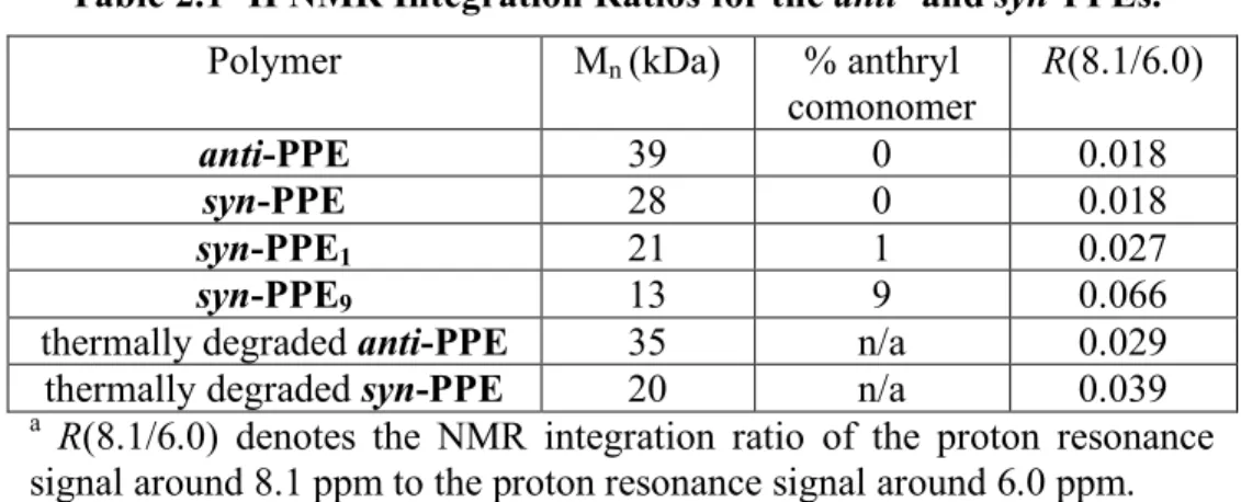
Table 2.1 1H NMR Integration Ratios for the anti- and syn-PPEs. 58 Table 2.2 Summary of Optical Properties of syn-PPEy Copolymers. 60
Table 3.1 Urinary Spermine and Spermidine Concentrations in Cancer Patients and Healthy Volunteers.
97
Table 3.2 Ratios of the Green Band Maximum Fluorescence Intensity to the Blue Band Maximum Fluorescence Intensity (Igreen/Iblue) in Aggregated Polymer Solutions
102
Table 5.1 Fluorescence Quantum Yields (Φ) for Solutions and Films of PPV1. 172 Table 5.2 Summary of gabs and glum Values for Solutions and Films of PPV1. 174
Chapter 1
1.1 Conjugated Polymers
Since the discovery of their conductive properties in 1977,1 conjugated polymers have been the subject of intensive research. This important discovery led to the Nobel Prize in Chemistry for 2000 being awarded to Shirakawa, MacDiarmid, and Heeger for their pioneering development of electrically conductive polymers.2-4 Conjugated polymers (also called conducting or semiconducting polymers) are, typically, organic macromolecules consisting of a backbone chain with alternating single and multiple bonds. The interactions between the molecular orbitals along the backbone chain result in an extended system of delocalized π-electrons. This conjugated π-electron system is responsible for the interesting electronic and optical properties exhibited from these organic materials. Several common examples of π-conjugated polymers are shown in Figure 1.1. N H S n n n n n n n H N n polyacetylene polythiophene polypyrrole polyaniline poly(para-phenylene) polyfluorene poly(para-phenylene vinylene) poly(para-phenylene ethynylene) PA PT PPy PAni PPP PF PPV PPE Figure 1.1 Common examples of π-conjugated polymers.
Conjugated polymers possess a unique combination of properties that set them apart from other materials: they have the mechanical properties and processing advantages of polymers, and they can also exhibit the electronic properties of metals and semiconductors. Another advantage that conjugated polymers have over inorganic materials is that their structures and properties can be easily tailored by organic synthesis. The diverse properties of conjugated polymers are finding use in a variety of applications including light-emitting diodes, field-effect transistors, chemical sensors, electromechanical actuators, and solar cells. Several monographs have been recently written about the synthesis, properties, and applications of conjugated polymers, and the interested reader is directed to a selection of these references for a more comprehensive introduction and review.5-11 In this chapter, we will introduce only the
fundamental details and prior research that are directly relevant to this thesis.
1.2 Photophysical Processes in Conjugated Polymers
In a small molecule containing an isolated double bond, a π-electron can be promoted from the highest occupied molecular orbital (HOMO) to the lowest unoccupied molecular orbital (LUMO) by the absorption of a photon with energy greater than the energy gap, Eg, between the two frontier orbitals (Figure 1.2). In comparison, a similar
molecule containing conjugated double bonds will have a HOMO higher in energy and a LUMO lower in energy. Since the orbital interactions resulted in a decreased energy gap, a lower-energy photon can promote a π-electron from the HOMO to the LUMO. In
a polymer consisting of similar repeating units that are conjugated with each other, the energy gap, Eg, can be even smaller.
As shown in Figure 1.2, the interactions between the molecular orbitals in a conjugated polymer lead to a band scheme analogous to that traditionally presented in solid-state physics for inorganic semiconductors (e.g., silicon).12 The mixing of the HOMOs produces a broadened, electron-filled band, analogous to the valence band of a semiconductor. Similarly, the mixing of the LUMOs produces a broadened, empty band, analogous to the conduction band of a semiconductor. As a consequence of
Figure 1.2 Schematic representations of the interacting highest occupied molecular orbitals (HOMO) and lowest unoccupied molecular orbitals (LUMO) in a conjugated system, the valence band and conduction band of a semiconducting polymer, and the corresponding energy gaps, Eg. Each single-headed arrow represents an electron, which can be excited from
the HOMO to the LUMO by the absorption of a photon (hν) having energy greater than Eg.
E
gE
gLUMO
HOMO
Valence Band
Conduction Band
n=1 n=2 n=3 n=4 H nHEnergy
H H i hν e -+these orbital interactions, π-conjugated polymers may exhibit semiconducting properties.
When a sufficiently energetic photon (hν) is absorbed by a semiconducting material, an electron can be promoted from the valence band to the conduction band, producing what is known as an “exciton.” An exciton is an excited-state quasiparticle consisting of an electrostatically bound electron–hole pair.13,14 This excited-state species can migrate from one location to another until it relaxes by some deactivation process. One of the most useful deactivation processes in conjugated polymers is luminescence (i.e., light emission).
Luminescence can be classified into two categories, fluorescence and phosphorescence, depending on the spins of the electrons involved in the radiative transition (Figure 1.3). If the excited electron has the same spin as the electron in the corresponding ground-state orbital, the emission of light is called phosphorescence. If the excited electron has the opposite spin as the electron in the corresponding ground-state orbital, the emission of light is called fluorescence. Phosphorescence involves an electronic transition from a triplet excited state (with unpaired electron spins) to a singlet ground state (with paired electron spins). Since this transition is formally forbidden by quantum-mechanical selection rules, it occurs at a much slower rate than fluorescence, which involves an allowed transition between a singlet excited state to a singlet ground state.15 Since electronic transitions between the singlet states and the triplet states typically occur at negligible rates in conjugated polymers, they will not be discussed any further in this thesis.
Figure 1.3 State energy diagram of some possible photophysical processes in a typical fluorescent molecule. Refer to the text for a detailed description.
There are many other photophysical processes that can occur in electronic excited states, and these can be illustrated in a state energy diagram, or Jablonski diagram (Figure 1.3). The singlet ground electronic state is denoted as S0, and the first
and second singlet excited states are denoted as S1, and S2, respectively. The first
triplet excited state is denoted as T1. Each of these electronic energy levels contains its
own vibrational energy levels, v = 0, 1, 2, etc.
Absorption of an energetic photon typically excites an electron from the lowest energy state (S0, v = 0) to S1 or S2. Usually, excited electrons rapidly relax by internal
conversion (a nonradiative transition accompanied by the release of heat) to the lowest vibrational level of S1. At this excited state (S1, v = 0), the singlet exciton exists long
important property for chemical sensors (vide infra). Eventually, the excited electron returns to its ground state by a deactivation process, such as fluorescence. Fluorescence involves electronic transitions from the lowest vibrational level (v = 0) of S1 to the vibrational levels (v = 0, 1, 2, etc.) of the electronic ground state (S0), and
these radiative transitions are denoted as (0,0), (0,1), (0,2), etc., respectively. Besides fluorescence, the excited state can also be deactivated by electron transfer or energy transfer processes involving a fluorescence-quenching defect or analyte (Q) or an emissive defect (D).
1.3 Fluorescence Quenching
1.3.1 Fluorescence Quenching by Analytes
Nonradiative electron transfer or energy transfer processes between a fluorescent molecule and another species (Q) can deactivate the excited state of the molecule. These nonradiative transitions compete with the fluorescence transitions, and therefore, decrease the fluorescence intensity of the molecule. This fluorescence quenching mechanism has been exploited to construct fluorescent chemical sensors.16 In 1995, our group demonstrated that the fluorescence-quenching sensory response towards an analyte can be amplified using a fluorescent conjugated polymer, which acts as a “molecular wire” (Figure 1.4).17,18
Figure 1.4 Schematic illustration of a molecular wire sensor exhibiting exciton formation, migration, and deactivation by electron transfer or energy transfer between the fluorescent conjugated polymer and a fluorescence-quenching analyte (Q).
The binding of a fluorescence-quenching analyte to a fluorescent conjugated polymer can provide an accessible, empty, low-energy LUMO to which an excited electron can be nonradiatively transferred. The efficient exciton transport properties in the conjugated polymer enables excited electrons from various locations along the polymer backbone to migrate to the binding site containing the analyte, resulting in the nonradiative deactivation of many excitons. Therefore, one quencher can dramatically decrease the number of fluorescence transitions of many conjugated polymer segments.
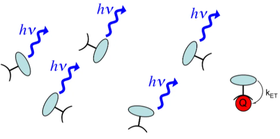
In comparison, a quencher in an unconjugated system of isolated fluorescent molecules can decrease the number of fluorescence transitions in only one molecule (Figure 1.5). Excitons created on molecules without bound analytes cannot migrate to
the binding site containing the analyte, so their fluorescence is unaffected by the quencher.
Figure 1.5 In an unconjugated system of isolated fluorescent molecules, one analyte (Q) can quench the fluorescence from only one molecule.
The amplified fluorescence-quenching response of conjugated polymers has been used to detect extremely small quantities of a variety of analytes, including explosives, metal ions, anions, proteins, carbohydrates, and nucleic acids.19,20
1.3.2 Other Fluorescence-Quenching Mechanisms
Besides interactions with a quenching analyte, a conjugated polymer may undergo fluorescence quenching by several other mechanisms. Notably, a conjugated polymer may experience fluorescence self-quenching, which is any interaction between an excited molecule, M*, and a ground-state molecule of the same type, M, that leads to fluorescence quenching of M*.13 For example, an intermolecular excited-state species, (MM)*, may be formed. This excited-state species, called an excimer, may be nonemissive or it may emit a lower-energy photon (see Chapter 2). Excimer formation
would compete with the usual fluorescence transitions; therefore, it would decrease the inherent fluorescence of a molecule.
Quantum-chemical calculations by Brédas et al. have suggested that the formation of π-stacked dimers or higher aggregates may also lead to decreased fluorescence intensities in conjugated polymers.21-25 They calculated that HOMO and
LUMO interactions between trans-stilbene molecules in a π-stacked dimer can lead to a splitting of the corresponding energy levels, resulting in a new HOMO and LUMO. Electronic transitions between the new energy levels are constrained by selection rules related to the symmetry of the dimer. The electronic transition between the dimer HOMO and LUMO is symmetry-forbidden, resulting in significantly weaker fluorescence from the dimer in comparison to that from isolated molecules.
Fluorescence quenching in conjugated polymers may also be facilitated by the formation of interchain species, called “polaron pairs,”26,27 which are interchain electron–
hole pairs held together by electrostatic interactions (similar to the usual intrachain excitons). The electronic transitions between an excited-state polaron pair to an electronic ground state are nonradiative and, therefore, quench the fluorescence of aggregated conjugated polymers.
The presence of chemical defects and impurities in a conjugated polymer can also lead to fluorescence quenching.28 For example, oxidative degradation in poly(p-phenylene vinylene) (PPV) can break the double bond of the vinyl group to produce a carbonyl moiety. The presence of carbonyl groups, which can be considered as π-electron acceptors, lead to nonradiative π-electron transfer processes between the PPV chains, resulting in fluorescence quenching of the polymer.22 In contrast to these
nonemissive carbonyl defects, which only reduce the inherent fluorescence intensity of the polymer, the presence of emissive defect sites can also produce new fluorescence transitions. The role of emissive defect sites will be discussed in greater detail in Chapters 2 and 3.
1.4 Exciton Migration in Aggregated Conjugated Polymers
The high sensitivity achieved by many conjugated polymer-based fluorescent chemical sensors relies on the efficient exciton migration (i.e., energy migration) properties of the semiconducting polymer. In a dilute solution, an exciton in a conjugated polymer can probe many repeating unit species, whereas the excited state of an isolated small molecule can only probe the binding sites in one molecule.17,18 As described earlier, if an exciton in a conjugated polymer migrates to a binding site containing a quenching analyte, the electron from the conduction band can be effectively trapped in the vacant, low-energy LUMO of the analyte (Figure 1.4). The electron transfer or energy transfer processes between the excited conjugated polymer and the quenching analyte are nonradiative transitions, and therefore, the inherent fluorescence of the polymer is effectively quenched by the analyte.
Exciton migration in a dilute conjugated polymer solution can be approximated by a one-dimensional random walk within an isolated polymer chain (Figure 1.6). In this model, excitons randomly move back and forth along the backbone chain with a high probability of revisiting the same polymer segments many times. Excitons exist for only a finite lifetime (e.g., 0.5 ns) before relaxing back to the ground electronic state by
fluorescence or another deactivation process, such as electron transfer to a quenching analyte (represented by the green octagons). Therefore, an exciton that revisits empty binding sites will be relatively inefficient at detecting a bound analyte.
Figure 1.6 Schematic representations of exciton migration in conjugated polymers in a dilute solution, an aggregated solution, and a solid film.
Exciton migration efficiency can be enhanced by decreasing the number of times an exciton revisits an empty binding site. This enhancement can be achieved by increasing the number of exciton migration pathways29,30 through polymer aggregation. In an isolated polymer chain, only intrachain exciton migration is possible. If the polymers are aggregated within close proximity to each other, interchain exciton migration becomes possible. In aggregated conjugated polymer solutions, this enhanced exciton transport increases the probability that an exciton will find a specific site in the conjugated polymer.
In a solid film state, conjugated polymer chains are aggregated in very close contact with many other chains. Therefore, excitons can move even more freely by a three-dimensional random walk, which means that an exciton will revisit an empty binding site only a minimal number of times before encountering a deactivation
pathway. The efficient exciton migration in conjugated polymer films has led to the development of very sensitive chemical vapor sensors. In 1998, our group reported the synthesis of highly fluorescent, electron-rich conjugated polymer films that underwent fluorescence quenching in the presence of trace amounts of electron-poor analytes, such as trinitrotoluene (TNT), a compound used in explosives.31,32
1.5 Aggregation Effects in Conjugated Polyelectrolyte-Based
Chemical Sensors
Aggregation-enhanced exciton migration in conjugated polymers has also played a role in the development of extremely sensitive solution-state chemical sensors. In 1999, Whitten et al. reported33 the sensitive fluorescence quenching of a dissolved conjugated polyelectrolyte (CPE), which is a conjugated polymer functionalized with multiple ionic groups.34 The authors found that the fluorescence of an anionic poly(p-phenylene vinylene) derivative (labeled as MPS-PPV in Scheme 1.1), was very effectively quenched by a dicationic analyte, dimethyl viologen (MV2+). The highly sensitive response, termed “superquenching,”35 was attributed to a combination of factors, including efficient exciton migration to quencher sites and a strong association between the cationic quencher and the polyanionic polymer, caused by electrostatic and hydrophobic interactions. However the authors did not recognize that the dicationic MV2+ also promoted aggregation between MPS-PPV chains even under dilute conditions, leading to other fluorescence quenching mechanisms.20
Scheme 1.1 Structures of MPS-PPV, MV2+, and MBL-PPV. n MeO O SO3 Li N N Me Me MPS-PPV MV2+ n MeO O Li MBL-PPV SO3 poly(2-methoxy-5-propyloxy
sulfonate phenylene vinylene) dimethyl viologen poly[5-methoxy-2-(4-sulfobutoxy)-1,4-phenylene vinylene]
Using a similar polyanionic polymer, Heeger et al. investigated the fluorescence quenching between MBL-PPV (Scheme 1.1) by the same dicationic quencher MV2+.36,37 The authors observed that as the quencher concentration increased, the efficiency of fluorescence quenching dramatically increased (superlinearly). This effect was initially attributed to a “sphere-of-action quenching mechanism” (an enhanced local concentration of quenchers in the proximity of the luminescent polymer),15 but many subsequent studies showed that analyte-induced aggregation of the conjugated polyelectrolyte chains was responsible for this effect.38-43 As discussed in the previous section, aggregation in conjugated polymers can lead to enhanced exciton migration to quenching sites, as well as other fluorescence-quenching processes. Thus, aggregation in conjugated polyelectrolytes can dramatically increase fluorescence quenching responses.
In another study, Heeger et al. also found that the fluorescence quenching efficiency increased as the number of positive charges on the viologen quencher increased.44,45 This result was attributed to the ability of highly charged quenchers to form more strongly bound complexes with the polyanionic conjugated polymer. It was
also attributed to a greater “sphere-of-action quenching mechanism” by highly charged quenchers. However, the enhanced fluorescence quenching by highly charged analytes could also be attributed to the ability of the additional charged sites to effectively induce interchain aggregation.41
The dependence of polymer aggregation behavior on the number of charged sites on an analyte can impart selectivity to the response of a chemical sensor (see Chapter 3). Unfortunately, aggregation in conjugated polyelectrolytes is not a very specific response, and a number of other factors can affect aggregation, including solvent polarity, solution ionic strength, interfering multicationic or multianionic species, and temperature. Despite the problem of nonspecificity, conjugated polyelectrolytes may still be useful in chemical sensing applications as components of sensor arrays.20
1.6 Nonquenching Analytes and Emissive Defects
Not all desired analytes for chemical sensing applications can directly quench the fluorescence of conjugated polymers by electron transfer or energy transfer processes. Such analytes are herein described as “nonquenching”.46,47 Additionally, not all defects in conjugated polymers are nonemissive like the carbonyl defect in degraded poly(p-phenylene vinylene) (PPV), described in Section 1.3. Taking another look at the state energy diagram in Figure 1.3, a low-energy, emissive defect (labeled as D) can provide another possible deactivation pathway for the excited state. Also, in Figure 1.6, the exciton trap sites (represented by the green octagons) may also refer to emissive species, not just nonemissive, quenching species. If low-energy sites are located in a
conjugated polymer, they will act as efficient exciton traps since exciton migration only advances from high-energy sites (e.g., the polymer segments) to low-energy sites, and not in the opposite direction. These low-energy sites can either nonradiatively quench the fluorescence intensity or emit low-energy photons. In Chapters 2 and 3, we will describe examples of nonquenching analytes and emissive defects that can significantly alter the fluorescence properties of conjugated polymers. We will demonstrate that a small concentration of emissive defect sites in a conjugated polymer can dominate the fluorescence properties of aggregated solutions and films.
1.7 Conformations of Conjugated Polymers in Solutions and Films
The electronic and optical properties of a conjugated polymer can be heavily influenced by how it is assembled and organized.48,49 As discussed in Section 1.3.2, intermolecular interactions between closely assembled conjugated polymer chains generally lead to self-quenching of fluorescence intensity. Intermolecular interactions may also lead to changes in transition wavelengths (i.e., the energies of emitted photons). For example, if two chromophores are adjacent to each other, their excited-state energy levels may interact with each other when one of the chromophores is excited. This delocalized excitation (exciton coupling)50 results in a splitting of theFigure 1.7 State energy diagrams for a J-aggregate, an H-aggregate, and an oblique orientation of two chromophores. The dashed arrows represent forbidden transitions, and the long, solid arrows represent allowed transitions. The pairs of small arrows represent induced electric dipoles in the interacting chromophores.
1.7.1 J-Aggregates and H-Aggregates
As shown in Figure 1.7a, if the electric dipoles of the two chromophores are organized in a top-to-bottom alignment (J-aggregate), only the transition to the lowest excited-state energy level is allowed by selection rules. Therefore, the lowest-energy electronic transition in a J-aggregate will be lower in energy than that in isolated chromophores (e.g., the aggregate absorption band will be red-shifted). In contrast, if the electric dipoles of the two chromophores are organized in a parallel alignment (H-aggregate), only the transition to the higher excited-state energy level is allowed by selection rules (Figure 1.7b). Therefore, the lowest-energy electronic transition allowed in an H-aggregate will be higher in energy than that in isolated chromophores (e.g., the aggregate absorption band will be blue-shifted). Since excited electrons rapidly relax from higher energy levels to the lowest energy excited state (as described in Section 1.2), and since the lowest-energy electronic transition is forbidden, fluorescence processes in an H-aggregate will be inefficient.
1.7.2 Chiral Orientations and Exciton-Coupled Circular Dichroism Spectroscopy If the two chromophores are arranged in an oblique orientation, electronic transitions to both excited-state energy levels are allowed (Figure 1.7c). Notably, if the chromophore orientation is chiral, then it can be probed by circular dichroism (CD) spectroscopy, which is a widely used technique for the conformational analysis of chiral molecules and materials.51-53 Chirality (i.e., handedness) is a geometric property of an
object being non-superimposable on its mirror image. Compared to ultraviolet–visible (UV–vis) absorption spectroscopy, CD spectroscopy can more easily detect exciton coupling in chromophores organized in a chiral orientation because the two electronic transitions involving the split energy levels give rise to CD signals (Cotton effects) that are oppositely signed. Importantly, the CD spectrum of exciton-coupled chromophores can also be directly correlated with the relative orientation of the two electric dipole transition moments (Figure 1.8).
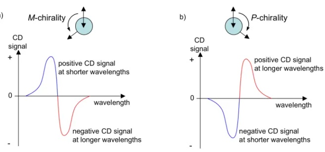
Figure 1.8 Illustration of the exciton chirality rule, which correlates a) a negative CD couplet to M-chirality, and b) a positive CD couplet to P-chirality.
According to the exciton chirality rule,54 when the electric dipoles are oriented in
a negative torsion angle (M-chirality), the long-wavelength component of the exciton couplet exhibits a negative CD signal and the short-wavelength component exhibits a positive CD signal (Figure 1.8a). This bisgnate spectral pattern is referred to as a negative CD couplet.55 Analogously, when the electric dipoles are oriented in a positive torsion angle (P-chirality), the long-wavelength component of the exciton couplet exhibits a positive CD signal and the short-wavelength component exhibits a negative CD signal (Figure 1.8b). This bisgnate spectral pattern is referred to as a positive CD couplet.55 Therefore, an exciton-coupled circular dichroism (ECCD) spectrum can
elucidate the chiral organization of the electric dipole transition moments of the interacting chromophores. In Chapters 4 and 5, we will use circular dichroism spectroscopy to probe the conformations of chiral conjugated polymers in solutions and films.
1.8 Controlling the Architectures and Properties of Conjugated
Polymer Films: Implications for Conjugated Polymer-Based Devices
Most conjugated polymer-based devices, such as light-emitting diodes, field-effect transistors, chemical vapor sensors, and solar cells, are constructed using conjugated polymers in their solid film state. Therefore, it is important to be able to understand and control the polymer film architecture in order to optimize device performance. For a solution-processed conjugated polymer, the final architecture in the solid film is dependent on how the polymer is assembled in its solution state.49,56-58 In
Chapter 4, we will investigate the relationship between the conformation of a chiral conjugated polymer in solution and its architecture in a solid film. To prepare a polymer film on a substrate, we employed spin-casting (i.e., spin-coating) deposition (Figure 1.9). This deposition technique involves applying an excess of a polymer solution onto a glass or quartz substrate and then rapidly spinning the system. The rapid spinning motion spreads the polymer solution evenly over the substrate by centrifugal force, and it also facilitates solvent evaporation, leaving behind a uniform polymer film on the substrate.
Figure 1.9 Illustration of spin-casting deposition of a polymer solution to prepare a uniform film, and fluorescence photographs of a solution (left) and spin-cast film (right) of a poly(p-phenylene vinylene) derivative (PPV1 in Chapters 4 and 5), irradiated with a 365 nm mercury lamp.
In Chapter 5, we will discuss how to transfer the conformational organization and optical properties of an aggregated conjugated polymer from the solution state to the film state. Controlling the organization-dependent properties of a conjugated polymer is important in optimizing deposition and processing techniques of films for conjugated polymer-based optoelectronic devices.
1.9 References
(1) Shirakawa, H.; Louis, E. J.; MacDiarmid, A. G.; Chiang, C. K.; Heeger, A. J. J. Chem. Soc. Chem. Commun. 1977, 578-580.
(2) Shirakawa, H. Angew. Chem. Int. Ed. 2001, 40, 2575-2580. (3) MacDiarmid, A. G. Angew. Chem. Int. Ed. 2001, 40, 2581-2590. (4) Heeger, A. J. Angew. Chem. Int. Ed. 2001, 40, 2591-2611.
(5) Conjugated Polymers: The Novel Science and Technology of Highly Conducting and Nonlinear Optically Active Materials; Brédas, J.-L.; Silbey, R. J., Eds.; Kluwer Academic Publishers: Boston, 1991.
(6) Conjugated Conducting Polymers; Kiess, H. G.; Baeriswyl, D., Eds.; Springer-Verlag: New York, 1992.
(7) Barashkov, N. N.; Gunder, O. A. Fluorescent Polymers; Ellis Horwood: New York, 1993.
(8) Conjugated Polymers and Related Materials: The Interconnection of Chemical and Electronic Structure; Salaneck, W. R.; Lundström, I.; Rånby, B. G., Eds.; Oxford University Press: New York, 1993.
(9) Advances in Synthetic Metals: Twenty Years of Progress in Science and Technology; Bernier, P.; Lefrant, S.; Bidan, G., Eds.; Elsevier: New York, 1999. (10) Roth, S.; Carroll, D. One-Dimensional Metals: Conjugated Polymers, Organic
Crystals, Carbon Nanotubes, 2nd ed.; Wiley-VCH: Weinheim, 2004.
(11) Handbook of Conducting Polymers, 3rd ed.; Skotheim, T. A.; Elsenbaumer, R. L.; Reynolds, J. R., Eds.; CRC Press: New York, 2007.
(12) Moliton, A.; Hiorns, R. C. Polym. Int. 2004, 53, 1397-1412.
(13) Turro, N. J. Modern Molecular Photochemistry; University Science Books: Sausalito, CA, 1991.
(14) Yan, M.; Rothberg, L.; Hsieh, B. R.; Alfano, R. R. Phys. Rev. B 1994, 49, 9419-9422.
(15) Lakowicz, J. R. Principles of Fluorescence Spectroscopy, 2nd ed.; Kluwer Academic/Plenum: New York, 1999.
(17) Zhou, Q.; Swager, T. M. J. Am. Chem. Soc. 1995, 117, 7017-7018. (18) Zhou, Q.; Swager, T. M. J. Am. Chem. Soc. 1995, 117, 12593-12602.
(19) McQuade, D. T.; Pullen, A. E.; Swager, T. M. Chem. Rev. 2000, 100, 2537-2574. (20) Thomas, S. W.; Joly, G. D.; Swager, T. M. Chem. Rev. 2007, 107, 1339-1386. (21) Cornil, J.; Heeger, A. J.; Brédas, J.-L. Chem. Phys. Lett. 1997, 272, 463-470. (22) Cornil, J.; dos Santos, D. A.; Crispin, X.; Silbey, R.; Brédas, J.-L. J. Am. Chem.
Soc. 1998, 120, 1289-1299.
(23) Brédas, J.-L.; Cornil, J.; Beljonne, D.; dos Santos, D. A.; Shuai, Z. Acc. Chem. Res. 1999, 32, 267-276.
(24) Cornil, J.; dos Santos, D. A.; Silbey, R.; Brédas, J.-L. Synth. Met. 1999, 101, 492-495.
(25) Cornil, J.; Calbert, J. P.; Beljonne, D.; Silbey, R.; Brédas, J.-L. Synth. Met. 2001, 119, 1-6.
(26) Yan, M.; Rothberg, L. J.; Kwock, E. W.; Miller, T. M. Phys. Rev. Lett. 1995, 75, 1992-1995.
(27) Wang, P.; Collison, C. J.; Rothberg, L. J. J. Photochem. Photobiol. A 2001, 144, 63-68.
(28) Yan, M.; Rothberg, L. J.; Papadimitrakopoulos, F.; Galvin, M. E.; Miller, T. M. Phys. Rev. Lett. 1994, 73, 744-747.
(29) Levitsky, I. A.; Kim, J.; Swager, T. M. J. Am. Chem. Soc. 1999, 121, 1466-1472. (30) Hennebicq, E.; Pourtois, G.; Scholes, G. D.; Herz, L. M.; Russell, D. M.; Silva, C.;
Setayesh, S.; Grimsdale, A. C.; Müllen, K.; Brédas, J.-L.; Beljonne, D. J. Am. Chem. Soc. 2005, 127, 4744-4762.
(31) Yang, J. S.; Swager, T. M. J. Am. Chem. Soc. 1998, 120, 5321-5322. (32) Yang, J. S.; Swager, T. M. J. Am. Chem. Soc. 1998, 120, 11864-11873.
(33) Chen, L. H.; McBranch, D. W.; Wang, H. L.; Helgeson, R.; Wudl, F.; Whitten, D. G. Proc. Natl. Acad. Sci. U.S.A. 1999, 96, 12287-12292.
(34) Pinto, M. R.; Schanze, K. S. Synthesis 2002, 1293-1309.
(35) Achyuthan, K. E.; Bergstedt, T. S.; Chen, L.; Jones, R. M.; Kumaraswamy, S.; Kushon, S. A.; Ley, K. D.; Lu, L.; McBranch, D.; Mukundan, H.; Rininsland, F.; Shi, X.; Xia, W.; Whitten, D. G. J. Mater. Chem. 2005, 15, 2648-2656.
(36) Wang, J.; Wang, D. L.; Miller, E. K.; Moses, D.; Bazan, G. C.; Heeger, A. J. Macromolecules 2000, 33, 5153-5158.
(37) Wang, J.; Wang, D.; Miller, E. K.; Moses, D.; Heeger, A. J. Synth. Met. 2001, 119, 591-592.
(38) Gaylord, B. S.; Wang, S. J.; Heeger, A. J.; Bazan, G. C. J. Am. Chem. Soc. 2001, 123, 6417-6418.
(39) Tan, C. Y.; Pinto, M. R.; Schanze, K. S. Chem. Commun. 2002, 446-447. (40) Pinto, M. R.; Kristal, B. M.; Schanze, K. S. Langmuir 2003, 19, 6523-6533.
(41) Tan, C. Y.; Alas, E.; Muller, J. G.; Pinto, M. R.; Kleiman, V. D.; Schanze, K. S. J. Am. Chem. Soc. 2004, 126, 13685-13694.
(42) Haskins-Glusac, K.; Pinto, M. R.; Tan, C. Y.; Schanze, K. S. J. Am. Chem. Soc. 2004, 126, 14964-14971.
(43) Jiang, H.; Zhao, X. Y.; Schanze, K. S. Langmuir 2006, 22, 5541-5543.
(44) Wang, D. L.; Wang, J.; Moses, D.; Bazan, G. C.; Heeger, A. J.; Park, J. H.; Park, Y. W. Synth. Met. 2001, 119, 587-588.
(45) Wang, D. L.; Wang, J.; Moses, D.; Bazan, G. C.; Heeger, A. J. Langmuir 2001, 17, 1262-1266.
(46) Lissi, E.; Abiuin, E. In Solubilization in Surfactant Aggregates; Christian, S. D., Scamehorn, J. F., Eds.; M. Dekker: New York, 1995, p 297-332.
(47) Lee, J. H.; Carraway, E. R.; Hur, J.; Yim, S.; Schlautman, M. A. J. Photochem. Photobiol. A 2007, 185, 57-61.
(48) Kim, J. Pure Appl. Chem. 2002, 74, 2031-2044.
(49) Schwartz, B. J. Annu. Rev. Phys. Chem. 2003, 54, 141-172.
(50) Kasha, M.; Rawls, H. R.; El-Bayoumi, M. A. Pure Appl. Chem. 1965, 11, 371-392.
(51) Circular Dichroism: Principles and Applications, 2nd ed.; Berova, N.; Nakanishi, K.; Woody, R. W., Eds.; Wiley-VCH: New York, 2000.
(52) Lightner, D. A.; Gurst, J. E. Organic Conformational Analysis and Stereochemistry from Circular Dichroism Spectroscopy; Wiley-VCH, Inc.: New York, 2000.
(53) Materials-Chirality; Green, M. M.; Nolte, R. J. M.; Meijer, E. W., Eds.; John Wiley & Sons: Hoboken, NJ, 2003; Vol. Vol. 24.
(54) Harada, N.; Nakanishi, K. Circular Dichroic Spectroscopy: Exciton Coupling in Organic Stereochemistry; University Science Books: Mill Valley, CA, 1983.
(55) Berova, N.; Nakanishi, K. In Circular Dichroism: Principles and Applications, 2nd ed.; Berova, N., Nakanishi, K., Woody, R. W., Eds.; Wiley-VCH: New York, 2000, p 337-382.
(56) Grell, M.; Bradley, D. D. C.; Long, X.; Chamberlain, T.; Inbasekaran, M.; Woo, E. P.; Soliman, M. Acta Polym. 1998, 49, 439-444.
(57) Ong, B. S.; Wu, Y. L.; Liu, P.; Gardner, S. Adv. Mater. 2005, 17, 1141-1144. (58) Hoppe, H.; Sariciftci, N. S. J. Mater. Chem. 2006, 16, 45-61.
Chapter 2
Enhanced Luminescence from Emissive Defects
in Aggregated Conjugated Polymers
2.1 Introduction
One of the most widely studied applications for conjugated polymers is in light-emitting diodes.1 Robust polymer light emitting diodes (PLEDs) with sufficiently long working lifetimes have been assembled using π–conjugated polymers that emit green, red, and yellow light; however, constructing a PLED with a stable, blue-emitting polymer film still remains a formidable challenge.2 One of the most popular classes of conjugated polymers for blue PLEDs is
polyfluorene and its derivatives (Scheme 2.1).3,4
However, the stability and working lifetime of these conjugated polymers are still limited.
Under normal operating conditions, the light emission from poly(9,9-dialkylfluorene) PLEDs can change in color from the desired blue to an unwanted green. The new, low-energy, green band in the polyfluorene emission spectrum was initially attributed to the formation of emissive aggregates and/or excimers.5,6 Generally, an excimer is an intermolecular excited-state species, (MM)*, formed by the interaction between an electronically excited chromophore, M*, and an unexcited chromophore of the same type, M (Equation 2.1).
(Eq. 2.1) Typically, excimers are spectroscopically characterized by broad, vibrationally unstructured, low-energy emission bands with long excited-state lifetimes.7,8 In addition to polyfluorene, conjugated polymer excimers have also been previously reported9 in heterocyclic, rigid-rod conjugated polymers,10-12 ladder-type poly(p-phenylene)s,13 and cyano-substituted poly(p-phenylene vinylene)s.14 Recently, our group has reported the
n C n
6H13
C6H13
Scheme 2.1 Polyfluorene, left, and a poly(9,9-dialkylfluorene), right.
!
synthesis of highly emissive conjugated polymer excimers based on poly(p-phenylene ethynylene) (PPE) containing [2.2.2] bicyclic ring systems having an alkene bridge substituted with ester groups, labeled in Figure 2.1a as anti-PPE.15 When anti-PPE was dissolved in dilute chloroform solution, the polymer chains were isolated from each other, so the emission spectrum (Figure 2.1b) was dominated by the inherent short-wavelength (0,0) emission of the polymer around 432 nm and the accompanying (0,1) emission7 at 459 nm. Emission at these wavelengths made the solution appear fluorescent blue when irradiated with ultraviolet light. However, when anti-PPE was aggregated in either a concentrated solution, a multilayer thin film, or a spin-cast film, it exhibited a new, low-energy, green emission band, similar to those observed in polyfluorene films. As the thickness of the spin-cast film increased, the emission intensity of the green band increased relative to the inherent blue emission of the polymer (Figure 2.1c). This effect was attributed to two factors. First, thicker films would have a greater probability of excimer formation since there would be a higher ratio of polymer–polymer interfaces relative to polymer–air and polymer–substrate interfaces. Second, thicker films would have enhanced exciton migration from high-energy sites (e.g., polymer chain segments) to low-high-energy sites (e.g., excimers). This phenomenon arises from migrating excitons being more efficient, according to random-walk statistics, at sampling a larger number of different sites in thick three-dimensional films than in thin two-dimensional films.16 In the present study, we investigated this phenomenon of aggregation-enhanced exciton migration in conjugated polymers, and we studied how it led to amplified green emissions from these PPE films.
Figure 2.1 (a) Structure of PPE, (b) normalized absorption and emission spectra of anti-PPE in chloroform solution (dotted line) and as a spin-cast film (solid line), and (c) normalized emission spectra of anti-PPE as a function of the absorption optical density (OD) of the film, indicative of its thickness, which was controlled by adjusting the concentration of the spin-casting solution. (Adapted with permission from reference 15, copyright 2005 American Chemical Society.)
The origin of the low-energy, green emission bands in various conjugated polymer films have been under much debate over the past few years. Several groups have recently argued that the green bands in the polyfluorene emission spectrum were actually not due to the presence of emissive conjugated polymer aggregates or excimers, but due to the formation of emissive on-chain defects.17-29 It has been proposed that polyfluorenes can easily undergo oxidative degradation, resulting in the formation of fluorenone defects sites on the polymer chain (Figure 2.2).
C6H13 C6H13 x+y C6H13 C6H13 y x O oxidative degradation
Figure 2.2 Oxidative degradation of poly(9,9-dialkylfluorene) to produce fluorenone on-chain defects.
MeO2C CO2Me CO2Me MeO2C C8F17 F3C n a) b) green band c) anti-PPE green band
Since conjugated polymer films are very efficient at funneling excitons from high-energy sites (e.g., the blue-emitting fluorene segments) to low-high-energy sites (e.g., the green-emitting fluorenone defects), only a small concentration of low-energy defect sites is necessary to effectively alter the polymer film emission from blue to green. This efficient exciton transport16,30,31 in conjugated polymer films makes them very sensitive to the presence of emissive defects, quenching defects, and emission-quenching analytes targeted for sensor applications.32-34 Therefore, we decided to further investigate the origin of the green emission bands from films of PPEs containing [2.2.2] bicyclic ring systems having an alkene bridge substituted with ester groups. We examined whether the green emission actually originated from excimers, as originally proposed,15 or from emissive defects similar to those in polyfluorene systems.
2.2 Results and Discussion
2.2.1 Preliminary Degradation Studies
One of the biggest limitations of implementing organic materials in semiconductor devices is the poor stability of many organic structures, leading to short working lifetimes relative to inorganic materials, such as silicon.2,35 Although this stability problem is well known in the field of conjugated polymers, it is still commonly overlooked. To investigate whether the green emission from films of anti-PPE originated from excimers or emissive defects formed by degradation, we characterized the polymer before and after purposely degrading it (Figure 2.3). First, anti-PPE (Mn =
2.2).36 This polymer was reported to have a relatively high ionization potential, partially
due to its electron-withdrawing, perfluorinated alkyl chains. For the present study, spin-cast films of the polymer were subjected to photodegradation in an ambient air atmosphere or in an inert nitrogen atmosphere. Both types of light exposure resulted in enhancements of the green band fluorescence intensity relative to the inherent blue (0,0) emission of the polymer (around 439 nm). For thermal degradation studies, a bulk sample of anti-PPE was heated to 300 ˚C in an inert helium atmosphere using a thermogravimetric–mass spectrometer (vide infra). The degraded polymer was then dissolved in chloroform, filtered, and then spin-cast into a film. Similar to those of the photodegraded polymer films, the fluorescence spectrum of the thermally degraded polymer also showed an enhanced emission intensity of the green band relative to the inherent blue (0,0) emission of the polymer (around 440 nm).