Publisher’s version / Version de l'éditeur:
Pulp and Paper Magazine of Canada, 64, 2, pp. T56-T62, 1963-04-01
READ THESE TERMS AND CONDITIONS CAREFULLY BEFORE USING THIS WEBSITE.
https://nrc-publications.canada.ca/eng/copyright
Vous avez des questions? Nous pouvons vous aider. Pour communiquer directement avec un auteur, consultez la première page de la revue dans laquelle son article a été publié afin de trouver ses coordonnées. Si vous n’arrivez pas à les repérer, communiquez avec nous à [email protected].
Questions? Contact the NRC Publications Archive team at
[email protected]. If you wish to email the authors directly, please see the first page of the publication for their contact information.
NRC Publications Archive
Archives des publications du CNRC
This publication could be one of several versions: author’s original, accepted manuscript or the publisher’s version. / La version de cette publication peut être l’une des suivantes : la version prépublication de l’auteur, la version acceptée du manuscrit ou la version de l’éditeur.
Access and use of this website and the material on it are subject to the Terms and Conditions set forth at
Buildings for paper mills. Part III: Some practical considerations in
design
Latta, J. K.
https://publications-cnrc.canada.ca/fra/droits
L’accès à ce site Web et l’utilisation de son contenu sont assujettis aux conditions présentées dans le site LISEZ CES CONDITIONS ATTENTIVEMENT AVANT D’UTILISER CE SITE WEB.
NRC Publications Record / Notice d'Archives des publications de CNRC:
https://nrc-publications.canada.ca/eng/view/object/?id=644e5da1-63e4-4287-aa73-65695f18c5f5 https://publications-cnrc.canada.ca/fra/voir/objet/?id=644e5da1-63e4-4287-aa73-65695f18c5f5no.
179
c .
2
NATIONAL RESEARCH COUNCIL
CANADA
DIVISION OF BUILDING RESEARCH
Buildings
for
Paper
Mills
Part
I I I
:
Some Practical ~ o n s i d l ~ r a t ' i o n ~
in Design
Reprinted
from
PULP AND PAPER MAGAZINE OF CANADA
- ,RESEARCH PAPER NO.
179
OF THE
DIVISION OF RITILDING RESEARCH
Price 10 cents
Ottawa
This publication is being distr:buted by the Division of Building Research of the National Research Council. I t should not be reproduced in whole or in p a r t , without permission of the original pub- lisher. The Division would be glad to be of assist- ance in obtaining such permission.
Publications of the Division of Building Research m a y be obtained by mailing the appropriate remit- tance, ( a Bank, Express, or Post Office Money Order or a cheque made payable a t p a r in Ottawa, to the Receiver General of Canada, credit National Research Council to t h e National Research Council, Ottawa. Stamps a r e not acceptable.
A coupon system has been introduced to make payments f o r publications relatively simple. Cou- pons a r e available in denominations of 5, 25 and 50 cents, and may be obtained by making a remittance a s indicated above. These coupons m a y be used for the purchase of all National Research Council pub- lications including specifications of t h e Canadian Government Specifications Board.
Buildings
for Paper
Mills
Part
Ill:
Some
Practical Considerations
in
Design
J. K. LATTA
Research
office^,Construction Section, Division of Bz~ilcliny Research, National Research Council
Water, in conjunction with other agents, is the most potent single cause of deterioration in buildings. The many harmful effects which water has on building ma- terials a r e reviewed followed by a n account of the sources of t h e water and some of t h e steps which can be taken t o control it.
I
T HAS been stated t h a t there would be no need f o r building research were i t not f o r the effect of water in the wrong places. This statement, like all such gen- eralizations, is an over-simplification and cannot be entirely supported. Nevertheless, the harmful effects of water on building materials can hardly be overem- phasized. If they did not exist, the construction of dur- able buildings would be greatly simplified and the task of the designer made much easier. I n this paper i t is intended to review, briefly, some of these harm- ful effects and to discuss various methods by which water can be controlled.H A R M F U L EFFECTS OF WATER Dimensional Change
With a change in moisture content many building ma- terials show considerable change in dimension, the magnitude of which may be greater than t h a t caused by normal temperature variations. Thus, if a material takes on water a t one period and releases it later, there will be a continuing expansion and contraction t h a t may lead to the destruction of the material or al- ternatively may break it loose from surrounding ma- terials. Two materials t h a t are bonded together and subjected to the same conditions may have different expansions and a warping effect may be produced similar to t h a t produced on a bi-metallic strip by changes in temperature. Composite building panels, f o r example, which have a facing material of a com- position different from the backing, may be subject to such warping. A differential moisture content through the thickness of a homogeneous material will produce a similar result, in much the same way as a difference i n temperature.
Paper presented a t the Seventeenth Engineering Confer- ence sponsored jointly by t h e Technical Section, Canadian Pulp and Paper Association, and by the Technical Asso- ciation of the Pulp and Paper Industry, and held in Mon-
real, October 15-18, 1962. Also presented a t the 49th Annual Meeting of t h e Technical Section, C.P.P.A., Montreal, J a n u a r y 22-25, 1963. This paper is not to be reproduced without permission of the above organizations.
Corrosion
Corrosion is largely an electrolytic action in which an electrical potential causes a current to flow if there is an electrolyte to complete the circuit. T h i s electro- lyte can be provided by any water in the building as- sembly which reaches the potential corrosion site. The electrical potential can be provided by two dissimilar metals or by one metal if there are salts i n the water. Even with pure water corrosion can take place if oxy- gen is present to combine with the hydrogen gener- ated and t h u s remove it, permitting the action to pro- ceed. As in many of the processes of destruction other agents must be present with the water before corro- sion takes place, but without water the material will not corrode.
Rotting
Rotting of wood is caused by the growth of fungi in the wood tissue; for rotting to take place several con- ditions must be satisfied. There must be food for the fungus to feed on, and t h i s is provided by the wood itself. There must be a i r ; if the wood is completely submerged t h e a i r supply is cut off and t h e decay will be stopped. The temperature must lie within a certain range with optimum conditions being between 70 and 90 deg. F. Finally, there must be a n adequate supply of water since the fungal spores do not germinate readily on wood which is below the f i b r e saturation point. With many woods t h i s point is reached at about 27 to 30 per cent of the oven-dry weight, but because of variations in the moisture distribution i n the wood i t is usually accepted t h a t t h e moisture content must be kept below 20 per cent t o stop rotting.
Blistering
When laying a built-up roof every precaution must be taken to prevent water f r o m being trapped either be- tween the plies or underneath the membrane. Should water become trapped and vapourized with the heat of the sun, t h e r e is danger of the formation of a blister in the roof, although passages can be provided through the insulation to relieve t h e pressure if t h e water is below the entire membrane. Such Dressure relief Das- sages cannot be provided between ilies of roofing ?elt, however, and water trapped in the thickness of the membrane will almost inevitably raise a blister and may also cause the roofing felts to rot. W a t e r trapped between felts is likely also to cause them to expand, or swell, t h u s adding to t h e possibility t h a t deteriora- tion will occur.
hem on the surface as the wate
ing very expensive materials and constr be argued that i t is better to let t h e
Liquid water moving through concrete and mortar can and designs provided the designer understands also cause a steady deterioration of these materials
by leaching out the calcium from the calcium silicate bonding materials. This action is most pronounced with soft or mildly acidic waters. Such waters may be produced in machine rooms by the pure condensed water vapour absorbing carbon dioxide from the air. If this water migrates through concrete roof beams, the calcium compounds may be dissolved from the cement and then left as stalactites when the drop of water re-evaporates. This condition was observed in one mill where there was no cementing material left on the undersides of the beams and they were covered with loose sand which could be brushed off by hand.
Freezing
The most striking feature of the Canadian climate is the long period of very cold weather that affects many parts of the country during the winter. I t is often thought that cold temperatures a r e responsible for much of the destruction that takes place in a build- ing envelope. I n actual fact, however, cold tempera- tures do not of themselves have any very serious ef- fect on the materials. Naturally, the large tempera- t u r e range between summer and winter will cause large expansions and contractions, but usually these can be allowed f o r by suitable expansion joints. On the other hand, the effect of freezing conditions in conjunction with water can lead to very rapid deteri- oration, and under extreme circumstances one freez- ing may be enough to shatter the material. The way in which destruction takes place is complex, but i t is known to depend upon a number of factors including the degree of saturation with water, the rate and num- ber of times of freezing, the strength and elastic properties of the material, and the nature of the pore structure in the material.
One of the mechanisms that produces frost damage is a n ice lensing action in which ice crystals tend to draw water from warmer regions in a manner simi- lar to t h a t causing frost heaving in soils. This mech- anism is now considered to cause more damage than does the expansion of water on turning to ice and as an indication t h a t this is so, materials have been destroyed by freezing organic liquids which contract on freezing.
I t is also possible f o r the expansion of water, on turning to ice, to cause destruction. This situation oc- curs when the water in a completely filled space or rela- tively large pore freezes rapidly and the excess water must flow away through the capillaries. If these capil- laries a r e too fine to permit sufficient flow quickly enough, relative to the speed of freezing, a pressure will be built up which may fracture the material.
NEED FOR CONTROL OF WATER
The list of the harmful effects of water in building materials and assemblies is a long one. In many in-
behaviour of water in its various forms and appl the necessary controls to prevent i t from accumul ing in harmful quantities.
The water that can be so harmful to buildings ca come from many sources such as rain and sno water vapour in the air, water leaking from pipes used for washing floors, walls, and equipment. It also in many cases a n essential ingredient in struction. The means by which the water may e the building envelope from these various sources the action needed to control it will now be discus
Rain
One obvious source of water is rain, particularly whe wind-driven. Considerable protection can be given
t
the walls of low buildings against vertically or nearly vertically falling rain by overhanging eaves and these should be provided where possible. For taller build ings (say over 20 ft.) their effect is proportionate1 less, and they are also less effective against 1blown by high winds.
iMasonry W a l l s . In the case of masonry walls i t has
been found that rain seldom penetrates through the masonry units themselves, but usually through cracks and fissures in the mortar joining them. These cracks can be caused by movement of the wall due to expan- sion and contraction or by differential settlement. An- other reason f o r fine hairline cracking is a poor bond between the masonry unit and the mortar, caused by a n incompatibility of the two items or by poor laying techniques. The precise mechanism by which the bond between the mortar and the masonry unit is estab- lished is still under investigation although i t is usual- ly considered necessary t o bring the two into intimate contact. Such contact cannot be achieved if t h e mortar is not plastic and workable when the unit is placed on it. A unit which exerts a strong suction may draw moisture out of the mortar as soon as i t i s placed on the lower course, causing i t to stiffen and making it incapable of forming a good bond with the upper course. Laboratory experiments have shown that a large amount of the leakage takes place a t the top of the mortar layer.
The suction of a masonry unit can be measured by wetting i t in l/s in. of water for 1 min., and observing the gain in weight due t o the water absorbed in that time. I n the case of bricks, the most satisfactory bond is given when this initial r a t e of water absorption is in the range of 5 to 20 gm. per 30 sq.in. of surface. Bricks with a high suction can have their suction re- duced to the optimum value by wetting them, but this is difficult to control on t h e job. The suction of the brick can also be reduced by pretreatment with a water- soluble silicone and a better bond may result [I].
I n conjunction with masonry units t h a t have the optimum suction i t is necessary to use a mortar that combines adequate water-retaining properties and
ity. T h e water-retaining properties measured by comparing t h e extent of flow o r spread when jarred on a f l a t table [2] be- f o r e and a f t e r i t h a s been subjected t o suction which draws moisture f r o m i t in t h e s a m e manner a s a n ab- sorptive brick [3]. Unfortunately, workability can- be measured so readily, b u t t h e difference in mor- of various composition is easily seen. Usually, a r s with h i g h w a t e r retentioil capabilities have
workability.
o r t a r composed of portland cement and s a n d i s characterized by h a r s h working properties and rela- tively low capacity to r e t a i n moisture against t h e suc- tion of a n absorbent brick. M o r t a r s composed of lime and sand, however, a r e usually h i g h in water-retain- i n g capacity and have excellent working qualities. The properties of w a t e r retentiveness and workability benefit f r o m increasing t h e proportion of lime but, since lime m o r t a r does not s e t in t h e s a m e manner a s ement mortar, i t may be necessary t o d r a w some moisture o u t of i t in order to s t i f f e n it. If t h i s is not done i t is possible t h a t under some circumstances t h e weight of succeeding courses may squeeze t h e still- plastic m o r t a r o u t of t h e lower joints.
Although i t was emphasized earlier t h a t t h e ma- jority of t h e r a i n which penetrates masonry walls passes t h r o u g h cracks between t h e m o r t a r a n d t h e masonry unit, i t does not follow t h a t t h e porosity of t h e masonry unit can be neglected. A highly porous material will soak up more w a t e r t h a n a n impervious one, and so may be more liable to damage. The pro- vision of impervious units, however, will not of itself produce a d r y wall if those units a r e n o t compatible w i t h the mortar used t o joint them.
I t is equally t r u e t h a t very s t r o n g nlortars a r e not always required t o make a satisfactory wall since t h e crushing s t r e n g t h of t h e wall does not increase in proportion t o t h e crushing s t r e n g t h of t h e mortar. I n one series of t e s t s on brick piers carried out ill G r e a t B r i t a i n , i t was found t h a t a pier made with a m o r t a r w i t h a crushing s t r e n g t h of 2000 p.s.i. h a d a s t r e n g t h of 2000 p.s.i. whereas one formed w i t h a 500 p.s.i. m o r t a r had a s t r e n g t h of 1500 p.s.i. T h u s i t can be seen t h a t walls of strength adequate f o r many p u r - poses can be constructed without using very s t r o n g m o r t a r a n d so, if a comparatively weak m o r t a r i s needed t o make a wall resistant to r a i n penetration, t h e r e need be little objection to i t s use. T h e important factor is, a s stated earlier, to obtain a complete bond between t h e m o r t a r and t h e masonry unit. I n general i t i s found t h a t if the u n i t s have a n initial w a t e r ab- sorption of between 5 a n d 25 gm. and a r e used with a m o r t a r having a lime content a t least equal t o one half the volume of Portland cement, a rain-resistant wall should result.
T h e effects of such good materials will be nullified, however, if t h e joints a r e not properly filled; t h e r e a r e several methods which can be used t o ensure t h a t they are. I n one such method t h e m o r t a r f o r t h e bed joint is spread to a uniform thickness o r only lightly furrowed. T h e head joints a r e formed by heavily but- t e r i n g t h e ends of s t r e t c h e r bricks a n d the edges of header bricks before they a r e placed. Filling of collar joints i s completed by slushing t h e m o r t a r in f r o m above. Other methods of filling t h e joints a r e by pouring i n g r o u t o r by shoving t h e brick with a side- ways motion into m o r t a r placed on t h e bed (pick-and- dip method).
Although t h e workmanship throughout t h e thick- ness of t h e wall i s probably of greater importance i n building satisfactory masonry walls, t h e method of
-
although they have t h e i r place, should not be used buildings subject to severe wind-driven r a i n . F such joints tends t o d r a w t h e m o r t a r a w a y f r units, whereas in f o r m i n g concave joints t h e mo compressed a n d a f i r m bond created between
t
and t h e m o r t a r a t t h e f a c e of t h e wall. T h i s is also excellent f o r shedding water. (Details ous methods of building masonry walls t h a t wi resistant t o r a i n penetration can be f o u n d in refer- ences 4, 5 a n d 6.)T r e a t m e n t of parapets w a r r a n t s special mention since these can be a prolific source of trouble, as they a r e exposed t o rain penetration f r o m b o t h sides and f r o m t h e top. I n addition to r a i n penetration they a r e also subject to severe freezing a n d to freeze- t h a w cycling. T h u s i t is essential t h a t r a i n should be prevented f r o m entering by means of a covering of impervious material on t h e back and t h e top. A through-flashing near t h e roof line will help in pre- venting a n y water which h a s penetrated f r o m perco- lating downward. I n addition this f l a s h i n g may assist in preventing moisture-laden air f r o m inside t h e building r i s i n g into the parapet t h r o u g h cracks.
One f u r t h e r mechanism which may promote t h e en- t r y of w a t e r into a wall should be mentioned since un- der some conditions i t i s possible f o r moisture t o be forced t h r o u g h the units a s well a s t h e m o r t a r under t h e effect of sun on a w e t wall. If t h e surfiice layers of t h e wall have been wetted by rain, h a v e absorbed some w a t e r , and then t h e surface i s warmed by t h e sun, t h e moisture n e a r t h e surface m a y move t o t h e cooler i n n e r p a r t s of the wall, t h u s r a i s i n g the mois- t u r e content of those parts.
C u ~ t a i n Walls. I n large panels of industrial-type cur- tain walls t h e r e a r e f e w e r joints t h r o u g h which t h e r a i n call be driven t h a n t h e r e a r e in a masonry wall. F u r t h e r m o r e t h e location of possible cracks is usually clearly established whereas in a masonry wall they may be quite random depending upon variations in t h e units, t h e m o r t a r , and t h e skill in laying. Movement under t e m p e r a t u r e variations which m u s t be allowed f o r will be g r e a t e r both because of t h e g r e a t e r length between t h e joints and because t h e s u r f a c e skin i s often much thinner and so will respond more rapidly to changes in temperature. Thus, although there a r e fewer joints, t h e problem of sealing t h e m may be more difficult t h a n i s t h e case in a m a s o n r y wall.
Rain penetration can occur in two d i f f e r e n t ways: water r u n n i n g down t h e f a c e of the panel may f i n d a channel which will direct i t through t o t h e inside, pos- sibly with t h e help of capillary action, o r wind pres- s u r e may force i t in t h r o u g h open joints. The f i r s t case should not be troublesome in a well-designed building, since t h e joints will be carefully detailed t o shed t h e w a t e r to t h e outside and flashings will be provided wherever they a r e needed. T h e possibility of a panel being erected incorrectly m u s t be gua against, however, a s m u s t the occurrence of cracks o r passages t h r o u g h the outer skin of the which could allow t h e w a t e r t o 'wick' in b y capillari
W a t e r blown in by wind pressure i s a more serio problem a n d careful t h o u g h t must be given to findi a satisfactory solution. R a i n carried by wind s t r i t h e face of t h e building a n d will then flow over surface u n d e r the combined action of gravity wind. Normally one thinks of i t a s r u n n i n g down, a t places where t h e a i r currents move upward o r across t h e face of t h e building, t h e w a t e r may be
iven in the same direction. When the film of water aches a joint in the impermeable facing i t may enter is joint by various means depending upon the na- r e of the gap. If the gap is narrow t h e water film 11 bridge i t and the water will be forced into the joint should there be a pressure drop through the wall. If the gap is too wide to be bridged by a film of water, t h e water may cling to t h e surface of t h e gap and be carried in by the drag of an a i r flow through the joint. In either case there will be a n a i r flow through the joint caused by the pressure drop through the wall. If the gap is bridged, t h e flow can be quite slow but may, nevertheless, be responsible f o r the passage of considerable quantities of water. If the gap is not bridged, a rapid a i r flow is needed to induce the neces- sary drag. For this reason, it is usually better to cauik a joint from the inside when possible rather than from the outside since even small cracks in the caulk- ing may reduce the air flow until i t cannot carry any water into the wide outer p a r t of the joint. If the caulking is on the outside any small cracks in it will be bridged by the film of water and the pressure drop through the joint will force i t in.
If i t were possible to seal the joint completely and so to eliminate all cracks then t h e perfect solution would have been achieved. In many cases this is at- tempted but the demands made on the sealing device a r e very severe. With reasonably large panels the movement to be accommodated by the joint caused by temperature variations can be very large. If a caulk- ing compound is used, it must continue to allow these movements without losing its elasticity or breaking the bond during the life of the wall. Alternatively the old compound must be raked out and t h e joint re- caulked. Other types of joint sealers may be used, such a s inflatable tubes, but these a r e usually expen- sive and will require some maintenance and replace- ment from time to time. Despite these drawbacks the 'sealed' joint is often used and gives satisfactory serv- ice.
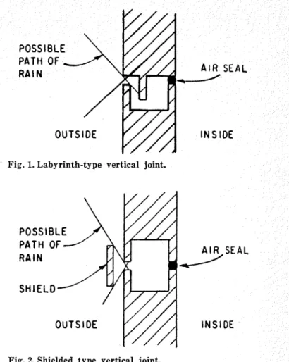
If i t is accepted t h a t perfection in sealing a joint cannot be achieved, a different approach to the p r o b lem must be adopted. I n this approach the quantity of water entering t h e joint must be reduced to a mini- mum; any water t h a t does enter the joint must be prevented from passing f u r t h e r in and causing trouble in the wall construction. I t is obviously important, therefore, t h a t there should not be a direct path through the joint through which rain could pass re- gard:ess of the angle a t which i t may strike the wal!. I t is also necessary t h a t the width of the joint be a s narrow a s possible to restrict the amount of rain t h a t can enter i t directly. This requirement unfortunately conflicts with the need to make the gap sufficiently wide to prevent i t from being bridged by a film of water. Expansion and contraction of t h e facing panel will cause the width of the gap to vary and the width when the panels have expanded to their greatest ex- tent will be the critical condition. To prevent water from passing straight through t h e joint a labyrinthian passage can be used a s shown in Fig. 1 or a shield can be placed in front of the joint a s shown in Fig. 2. The shield actually provides both a labyrinth a s well a s preventing rain drops entering directly.
Despite these precautions some water will enter the joint either by splashing of rain drops, running down from above or by being blown sideways across the face of the panel. This water must be prevented from working its way further through the joint by reducing the drag of the air flow on it. This can be achieved by reducing the air flow through the joint
A I R SEAL
d
INS ID€
Fig. 1. Labyrinth-type vertical joint.
INSIDE
Fig. 2 Shielded type vertical joint.
to a minimum by 'sealing' t h e joint a t t h e inner face of the wall. The air flow will then be restricted to the amount leaking through the seal together with t h a t which enters the joint a t one point to return to the outside a t another under the action of pressure differences on the face of the building. Furthermore, i t is necessary to reduce t o a minimum t h e velocity of the a i r which does enter t h e joint by increasing the cross-sectional area behind the outer face. This wid- ening can have the additional advantage of increas- ing the path along which t h e water must flow before i t reaches t h e a i r seal. T h i s seal must not become wet since if i t is, the water will bridge the small cracks in it and be forced into t h e building just a s it would through cracks in a joint 'sealed' a t the outer face.
I n summary, the joint must be designed t o restrict the direct entry of rain, t o intercept the water which does enter, to reduce to a minimum the volume and velocity of t h e air passing through the joint and to provide a s long a path a s possible between the outer face and t h e air seal. One way to meet these require- ments is t o construct a separate rain screen in front of the main wall, held out from i t by suitable brack- ets. This provides an infinitely long path along the wetted surface of the joint between the entrance of the joint and the inner airtight wall. The a i r flow in the space behind the rain screen may have to be re- stricted by vertical and horizontal baffles. Great ad- vances have been made by t h e Norwegian Building Re- search Institute in develpoing rational methods of design to restrict water entry [7].
Whatever method is adopted to provide raintight joints, i t is necessary to consider each case on its own merits since the conditions will vary from building to building and no one solution can be applied in all sit- uations.
Roofs. The basic function of a roof is to keep the rain out of a building. Since i t is always possible f o r any device to fail to carry out its function, i t may al- low the water to leak in. The roof covering is usually supported by a deck of some sort, very often with a layer of insulation between them, and so i t is not al- ways clear t h a t the roof is leaking until there is a general disintegration of one or more of the various components forming the roof structure. When this happens, i t is sometimes difficult to determine whether the water entered the roof assembly from the outside a s rain or from t h e inside a s vapour. Thus the roof should always be examined critically f o r any possibil- ity of leakage. This critical approach should s t a r t with the initial design, follow through the construction stage, and continue throughout the whole life of the roof.
With pitched roofs covered with overlapping shingles, rain is shed from the higher to the lower shingles and i t is obviously essential t h a t there should be no path which water running down the roof could follow and work its way through to the inside. I n ad- dition, i t is necessary t h a t there be sufficient overlap on the shingles so t h a t rain cannot be blown up under- neath the shingles and penetrate into the roof. I t is normally accepted t h a t the vertical rise up which the water must be blown to enter the building should equal the wind pressure expressed in inches of water column. In contrast, built-up roofs a r e often laid flat or even 'dished' since they rely upon the bituminous ma- terial used in their construction to form a continuous waterproof membrane. The roofing felts are incor- porated in the roof to bind the mastic together and prevent i t from cracking. Thus i t is clear t h a t a full coat of mastic over the entire roof cover is a prime requirement for a waterproof roof. Since the roofing felts overlap one another, it is important that they a r e well bonded together, otherwise water which pene- trates between the layers will be able to work its way through the roof covering. To ensure a complete cov- erage of bitumen, either pitch or asphalt, sufficient material must be used and a full mopping given to the area being covered by the felt. The felt should then be unrolled onto the hot bitumen and should push a small wave ahead of i t while this is being done. After this t h e felt should be firmly pushed down onto the bitumen, usually by brushing with stiff brooms. The practice of workmen shuffling i t out with their feet is not adequate. The other practice of cutting the required length of felt from the roll and laying i t onto the bitumen may be equally bad since i t is almost in- evitable t h a t a i r bubbles will be trapped and a bond with the bitumen prevented.
I t is also important t h a t the bitumen should be a t the right temperature when the felts a r e rolled out onto i t which means t h a t there must be no undue delay a f t e r i t has been removed from t h e kettle. I t is equally, if not more, important to ensure t h a t i t is not overheated in the kettle since this will drive off some of the oils which give the material its desirable flexi- bility. Coal t a r pitch should be kept i n the range of 325 to 375 deg. F. and asphalt between 400 to 430 deg. F. (Further information about built-up roofs is contained i n Canadian Building Digest 24 [8].)
Both in walls and roofs the importance of good flashing to shed water to the outside cannot be over- stressed. If good laying techniques a r e followed it is a relatively easy matter to construct a waterproof roof over a plain flat unobstructed roof deck. When this deck is broken by vents, f a n outlets, skylights, and other obstructions, the difficulties a r e compounded.
Each obstruction has to be treated individually thus irltcrrupting t h e process of laying the roof, increasing the risk of rain penetration and adding to t h e cost.
W a t e r Vapour
Vapour Flozu. Rain penetration from outside is only
part of the story. Another most important source of water which may enter t h e building envelope and cause damage is the water vapour in the a i r inside the building. This water vapour is invisible and not readily sensed and until comparatively recently has not been recognized as a troublesome source of mois- ture.
F o r most cases met in building construction a mix- ture of water vapour and a i r can be considered a s a mixture of two gases. I t then follows t h a t in many respects the two gases act independently of one an- other and so t h e water vapour may pass into the build- ing envelope even though t h e a i r is stopped. Water vapour moves under the influence of a vapour pres- sure differential which may exist between t h e inside and the outside of the building envelope. T h i s differ- ence is greatest in winter when the cold outside tem- perature holds the outside vapour pressure below a low value. I t is in winter, then, t h a t the maximum amount of water can accumulate in the building en- velope under this action.
Unfortunately, in many cases, this is not a simple problem: some of the difficulties which m a y be en- countered have been described in P a r t I1 of this series [9]. It was shown t h a t the total moisture flow through a building material can be regarded a s t h e algebraic sum of a vapour flow under a vapour pressure dif- ferential and a liquid moisture flow under a moisture content differential. The mechanism involved in these phenomena is rather complex but the basic practical approach to t h e problem can be stated. This is to pre- vent a s f a r a s possible t h e entry of t h e w a t e r in the f i r s t place and to make provision f o r t h e escape of any water which does enter the building envelope. With the exception of one class of material, which will be mentioned later, the basic requirement i n prevent- ing the entry of water from the interior of the build- ing is a good vapour barrier on the inside face since most of t h e water enters a s water vapour. Sometimes liquid water will be present on the surface either as a result of condensation or from leakage b u t usually, if the requirements to prevent the entry of water vapour a r e met, the liquid water will also be kept out. Thus to avoid a potentially harmful accumulation of water in t h e building envelope, i t is essential that the flow of moisture from inside the building to any point in the envelope is always less than t h e potential flow from t h a t point to the outside. This result can be obtained in two different ways or by
a
combination of both. Firstly the resistance of the inner face to vapour flow can be increased by t h e application of a suitable vapour barrier and secondly, the resistance of the outer skin can be reduced either by ventilation behind i t or by selecting materials which will permit the pas- sage of vapour. In designing a building, it is neces- sary to calculate the potential vapour flow in to and out of the envelope in order to ensure t h a t there is no accumulation of condensation. I t is a t this stage that the effects of liquid moisture migration are most confusing and i t is left to t h e designer to make a suit- able allowance for i t a s best h e can. In view of the dif- ficulty in doing this, i t i s usually wisest t o provide the best possible vapour barrier to restrict the entry of moisture in the f i r s t place and to control the liquid moisture migration by means of a i r gaps,is not amenable to cal be handled by intelligent gu
borne in mind t h a t water vapour has a slow r a t e of on through still air. ~ h u s diffusion alone can-
relied upon to promote t h e escape of water from a n enclosed space and there must be a ent of a i r to carry the vapour. I n the case of or low pitch roofs which have ventilation pas- sages between the insulation arid the roof membrane, this flow can most readily be promoted by leaving these passages open a t t h e eaves so t h a t the wind can blow through freely. Gooseneck breathers only on a roof a r e not sufficient to promote the flow since they can only act under a difference in pressure caused by a chimney effect which will be small in this case be- cause they will all be a t more or less the same eleva- tion.
A considerable amount of work on this subject has been done by t h e Norwegian Building Research Insti- tute and is described in their publication entitled 'Ventilated and Unventilated Flat, Compact Roofs'
[lo].
One class of insulating materials which may not normally require a vapour barrier is composed of those materials which have t h e ability to wick the moisture back to t h e warm face t h u s raising the rela- tive humidity there and counteracting the f u r - t h e r entry of vapour from the air. I n this case any- thing which partially seals the face may cause t h e moisture content of the material to build up. Exam- ples of materials which behave in this manner a r e foamed concrete and sprayed asbestos fibre. Unfor- tunately the conditions under which they will operate satisfactorily without a vapour barrier are not yet well established.
One saving grace in t h e matter of vapour migration through building envelopes is t h e ability of some ma- terials o r the type of construction to absorb limited quantities of water without harm and then to release this water later. Since t h e greatest accumulation of water takes place in winter this cycle is often a sea- sonal one. Naturally t h e effects of moisture expansion and contraction and the danger of freezing when wet will have to be considered before this action can be relied upon.
Air
Movement. As stated earlier, t h e water vapour in the a i r inside the building behaves in some respects a s a n independent gas, but, despite this, will be carried along in a moving stream of air. Thus although vapour migration on its own is one method of moving mois- ture into the structure, a i r leakage through cracks and other openings is a second and potentially more pow- erful mechanism. The a i r , in passing through passages i n the structure, carries water vapour with i t ; this vapour may condense on some colder point in t h e wall o r roof. A pressure differential must exist across t h e building envelope before this a i r flow can take place and this differential can be caused in several ways. Wind action will cause a suction t o be created on the leeward side of a building over much of the roof sur- face and also in many other locations depending upon the size and shape of t h e building. Even on the wind- ward face of a tall building a suction can exist over a narrow s t r i p up the edges and across t h e top. This ef- fect is particularly serious a t the top corners. Strong suctions may be produced also on t h e windward top corner of a building where the wind is blowing diag- onally across it. Discussions on the nature of windand wind action on buildi 121.
Wind action is, of course, intermittent and a p a r t of a building which is subjected to a suction one day may have a pressure on i t on another, but since a large quantity of water can be deposited in t h e passages through the envelope in quite a short t i m e the wind effect may be serious. On the other hand, t h e chimney action may be continuous over long periods. Chimney action is produced by the a i r inside a heated buildir~ being warmer and less dense than t h a t outside, thu causing a pressure which tries t o force a i r out of
t
top of the building. If the a i r can escape, i t will car1 moisture with it. The chimney effect could be a mented by a pressure set up in the building by ventilation system. In some buildings a slight p sure is created deliberately in an e f f o r t to com d r a f t s and so to increase t h e comfort of t h e occupan and reduce the heating load. In addition to bein harmful to the building structure a t some points forcing in moisture, the small pressures induced seldom sufficient to overcome the effects of wind p sure on any other than t h e calmest days when drafts a r e not serious anyway.Throughout this section the emphasis has b placed upon the outward movement of a i r rather t h the infiltration caused by positive wind pressures. The inward flow of a i r is seldom harmful to a buildin cept when it carries rain with it. Outside air wh infiltrates through the building envelope usually counters steadily increasing temperatures. Thus, e though i t may be saturated, these warming conditio will reduce the relative humidity and prevent co densation. On the other hand inside a i r moving o ward will be cooled with a n increasing danger of con- densation.
Leakage and Wash Water
Water t h a t may penetrate the building envelope from inside is not all carried by the air. Some may be i n the form of liquid water which can come from leaking pipes, etc., or from water used for washing. Some of the water may have been carried by t h e air a t one stage but condensed on cold pipes or f r e s h air ducts and similar cold surfaces, and then has run down o r dripped off to come in contact with t h e building en- velope. Some building materials may then soak up this water and so give it an opportunity to destroy the ma- terial. Surface condensation on cold walls may also be instrumental in initiating t h e processes of deteriora- tion.
Construction Water
A source of water t h a t must be recognized and dealt with is t h a t introduced into the construction either of necessity or by accident during erection of the build- ing. Many construction materials, such a s concrete, require water in the process of manufacture. Obvious- ly concrete cast on site will be saturated a t the time of placing and good practice requires considerable care to be exercised over the drying-out process. It should also be realized t h a t factory-made concrete units may also contain considerable quantities of water a t the time of delivery to t h e site.
In addition to the water deliberately introduced into the building materials during construction, it is pos- sible for large quantities t o be introduced accidentally either by r a i n or by carelessly handled o r leaky hoses. Sometimes materials become wet through improper storage b u t very often i t i s impossible t o protect them once they have been set i n place, without resorting t o
Ae uilding the designer has a mul- to
him only a small segment not something whic ed in this paper. I n addi- up' a building. tion to the problems presented by water he must cope count the man
with consideration of layout, foundation and construc- may rapidly deteriorate and require frequent ma 1 stability, and mechanical and electrical services. nance.
R E F E R E N C E S
8. BAKER, M. C., Built-up roofing. National Research Council, Division of Building Research, Ottawa, De- cember, 1961. CBD 24.
9. LATTA, J. K., Buildings f o r paper mills. P a r t 11- .-cube specimens), p. 124-130. Some fundamental considerations. P u l p P a p e r M a g .
C91-60. Standard Specifications f o r Can. 63, no. 9 :T449-454 (Sept. 1960). (reprinted a s NRC 7089).
10. HOLMCREN, J., and ISAKSEN, T., Ventilated and un- ventilated flat, compact roofs. Norwegian Building search, Ottawa, June, 1960. CBD 6. Research Institute, Oslo, 1959. Report No. 27, 158 p. ITCHIE, T. Cavity walls. National Research Council, (available in English).
Division of Building Research, Ottawa, September, 11. DALCLEISH, W. A., a n d BOYD, D. W., W i n d on build- 1961. CBD 21. ings. National Research Council, Division of Build-