HAL Id: insu-02270107
https://hal-insu.archives-ouvertes.fr/insu-02270107
Submitted on 23 Aug 2019
HAL is a multi-disciplinary open access
archive for the deposit and dissemination of
sci-entific research documents, whether they are
pub-lished or not. The documents may come from
teaching and research institutions in France or
abroad, or from public or private research centers.
L’archive ouverte pluridisciplinaire HAL, est
destinée au dépôt et à la diffusion de documents
scientifiques de niveau recherche, publiés ou non,
émanant des établissements d’enseignement et de
recherche français ou étrangers, des laboratoires
publics ou privés.
Combining a High-Level Design Tool for Safety-Critical
Systems with a Tool for WCET Analysis on Executables
C Ferdinand, R Heckmann, T Le Sergent, D. Lopes, B Martin, X Fornari, F.
Martin
To cite this version:
C Ferdinand, R Heckmann, T Le Sergent, D. Lopes, B Martin, et al.. Combining a High-Level Design
Tool for Safety-Critical Systems with a Tool for WCET Analysis on Executables. Embedded Real
Time Software and Systems (ERTS2008), Jan 2008, toulouse, France. �insu-02270107�
Combining a High-Level Design Tool for Safety-Critical
Systems with a Tool for WCET Analysis on Executables
C. Ferdinand
1, R. Heckmann
1, T. Le Sergent
2, D. Lopes
2, B. Martin
2, X. Fornari
2, F. Martin
11: AbsInt Angewandte Informatik GmbH, Science Park 1, D-66123 Saarbr ¨ucken, Germany 2: Esterel Technologies, 9 rue Michel Labrousse, F-31100 Toulouse, France
Abstract: Synthesizing code from model-based software specifications using automatic code gener-ators such as the SCADE Suite allows design verifi-cation at early project stages and helps to avoid cod-ing errors, thus reduccod-ing the need for low-level test-ing. Non-functional properties of the implementa-tion such as execuimplementa-tion time and memory consump-tion require specific analysis. Static program anal-ysis tools like AbsInt’s StackAnalyzer and timing analyzer aiT complete ideally the model-based de-sign process with the verification of these proper-ties. These tools can also give SCADE users a di-rect feedback on the effects of their design decisions on resource usage, allowing them to select more ef-ficient designs and implementation methods. The SCADE tool, StackAnalyzer and aiT can be inte-grated in a way that the analysis results for code generated by the SCADE tool are conveniently ac-cessible from within the SCADE development envi-ronment. We present the tools and their integra-tion, preliminary results, and plans for integration with other tools for timing analysis.
Keywords: Model-based code generation, timing
analysis, stack-usage analysis
1. Introduction
Software developers in the avionics sector face some specific challenges: Many software systems are safety-critical and, thus, must achieve high quality objectives. Model-based design aims at sat-isfying the high safety requirements in combina-tion with good development productivity by start-ing with a software specification. The implemen-tation process is not necessarily automatic. It is therefore still possible to introduce software defects through misinterpretation of design and specifica-tion documents or through human error during the manual coding process. Automatic code generators such as the one provided by SCADE are increas-ingly used to generate the implementation from the specification. By creating C code directly from the model-based specification, these code genera-tors avoid the typical translation problems that oc-cur in the implementation stage. Moreover, as the SCADE Suite code generator, SCADE KCG, is
qual-ified as a development tool w.r.t. DO-178B level A, unit testing on the generated code can be avoided. Many design and implementation errors are avoided by synthesizing code from specifications. However, non-functional properties such as ab-sence of memory overflow and timer overruns are still an issue. To verify such properties of the imple-mentation, unit tests and runtime measurements are currently widely used in the industry. These approaches have some limitations:
• To acquire a high level of confidence to have detected the worst-case (or close to worst-case) behaviors, a huge (often prohibitive) number of test cases needs to be considered.
• Testing to detect worst-case memory and /or timing behavior can be complex and time-consuming. The results are often only avail-able late in the development cycle and cannot be used to optimize the model during the devel-opment.
Recent advances in the area of static program anal-ysis based on abstract interpretation led to the de-velopment of tools to automatically detect worst-case execution times (WCET) and worst-worst-case stack usage like AbsInt’s timing analyzer aiT and Stack-Analyzer (see [10] for a survey of timing analysis tools). Such tools that determine safe and precise bounds on resource usage can be very helpful for SCADE users.
In the context of safety-critical hard real-time ap-plications, aiT and StackAnalyzer are used as veri-fication tools, i.e., they are used to demonstrate and prove that pieces of code are guaranteed to always execute within limited time intervals and resource bounds.
In this paper, we propose to complement model-based design processes with static program anal-ysis tools. We argue that to develop hard real-time systems, model-driven development coupled with detailed analysis of the implemented software is much better suited than traditional development methods that rely on programming C code.
The users of SCADE usually work on a much more abstract level than the producers of manual code.
Our tight integration enables the SCADE user to conveniently access static analysis results from within the SCADE development environment. This gives SCADE users a direct feedback on the effects of their design decisions on the resource usage, al-lowing them to select more efficient designs and im-plementation methods.
In the following, we present the tools, the experi-mental integration, preliminary results and plans for further tool integration.
2. SCADE Language and Toolset
SCADE is a model-based design tool dedicated to the development of safety-critical embedded sys-tems that require certification, for example sub-ject to DO-178B, IEC 61508, EN 50128, or ISO 26262 standards. SCADE modeling capabilities cover the design, verification, and optimization of complex algorithms, control intensive applications, and graphic interfaces. Furthermore, the SCADE automatic code generator has been qualified to pro-duce a portion of the evidence mandated by certifi-cation authorities, supporting a safety-critical pro-cess in a cost-effective manner.
The SCADE language provides a graphical and textual notation to express data-flow and control-flow. The data-flow is defined in a declarative way through equations and the control flow is expressed with control structures that go from simple “if-then-else” like constructs to complex hierarchical and parallel state machines called Safe State Ma-chines (SSM). In SCADE 6 both data-flow and SSM formalisms can be mixed and nested one into the other without limitation (see section5), with both formalisms sharing the same fundamental inter-pretation and characteristics, namely:
• Explicit data typing,
• Explicit management of discrete time, • Single assignment in data-flow,
• Concurrency solved through synchronous be-havior and data and control dependencies, • Deterministic execution.
Figure 1: SCADE operator modCount Figure1pictures a simple SCADE dataflow opera-tor. The predefined SCADE operator FBY is a
de-lay of n ticks, n being its first parameter; at ini-tialization the output value is given by the second parameter, here 0. The operator defined in Figure1 is a simple counter modulo the value modulo pro-vided as input. The counter value is incremented at each tick in which input incr is true. Output
rippleClockis true when the counter is reset by the modulo operator.
Figure 2: SCADE operator countTime1 An operator can be instantiated several times as in Figure 2. The instance number appears at the top right corner of the instance. Instance 1 of
modCountincrements the output at each tick (in-put incr is always true). Each time it is reset, it causes an increment in the second instance of
modCountbecause the output rippleClock of the first instance is connected to the input incr of the second. Same for the 3rdinstance that counts only when the 2ndinstance reaches 60. The output of the operator countTime1 is a vector of 3 integers that represents the time in [seconds, minutes, hours] if it is called at every second.
SCADE 6 introduces loops via iterator constructs as a means to perform computations on arrays. It-erators come in two families:
• Map iterators, which apply a SCADE 6 operator to a bunch of arrays of identical size as input, and produce a bunch of arrays of the same size as output. The SCADE 6 operator is applied to each array component independently. A map it-erator can be used to compute the sum of two vectors for instance (c[i] =a[i] +b[i]).
• Fold iterators, which apply a SCADE 6 operator to an array and an accumulator, iterating from the first array cell to the last one. Each compu-tation is applied to the value of the current cell and the previous accumulator value, leading to a new accumulator value. The final result is the
last accumulator value. A fold iterator can be used to sum up all the cell values of a given ar-ray (b=a[0] +a[1] + · · · +a[n−1]).
Both families of iterators have variants that use a stop condition. As soon as the condition is false, the iteration stops. In all cases, the generated code is guaranteed to generate bounded loops that have statically determined iteration bounds.
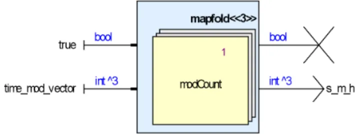
Figure 3: SCADE operator countTime2 An additional iterator, mapfold, is a combination of map and fold. It can be used to implement the functionality of countTime1 in a more concise way (see Figure 3). The mapfold iterator, as all iterators, applies to an operator (here modCount), and is used with an iteration number of 3 in this case, as we want to instantiate modCount 3 times. The first input of an operator under a mapfold is the accumulator input, while the first output is the accumulator output. With SCADE constant
time_mod_vector defined as [60, 60, 24], the be-havior of operator countTime2 is the same as the one from countTime1.
From a SCADE design, the SCADE code genera-tor generates a set of C functions, forming a call graph from a root function that executes one step of computation. Another set of functions is also gen-erated for the initialization of the memory that is the context on which the step function is applied. To develop a complete embedded application, these functions (reset and cycle) must be called from a main function that also integrates calls to drivers, and interacts with the underlying Operating Sys-tem. This code generated by SCADE is in general extended by hand-written user integration code. Then all that code must be compiled and linked to get an executable that can then be downloaded on the target.
The code generated by KCG from operator
countTime2is given below.1 The reset and cycle functions call respectively the reset and cycle func-tions generated from operator modCount within a loop that implements the mapfold iterator.
1The formatting has been changed to let the code fit better to the given column width.
void countTime2_reset(outC_countTime2 *outC){ kcg_int i;
for (i = 0; i < 3; i++) {
modCount_reset(&outC->Context_modCount[i]); }
}
void countTime2(outC_countTime2 *outC) { kcg_bool tmp; kcg_int i; /* P1::countTime2::_L3 */ kcg_bool _L3; _L3 = kcg_true; for (i = 0; i < 3; i++) { modCount(_L3, time_mod_vector[i], &outC->Context_modCount[i]); outC->s_m_h[i] = outC->Context_modCount[i].count; tmp=outC->Context_modCount[i].rippleClock; _L3=tmp; } }
SCADE KCG has several optimization options. One of the most interesting is the ability to inline the equations from any operators as first step of the compilation. This allows inter-operator optimiza-tions. Generated code from countTime2 with
modCountinlined is shown below.
void countTime2_reset(outC_countTime2 *outC){ kcg_int i;
for (i = 0; i < 3; i++) { outC->init_1[i] = kcg_true; }
}
void countTime2(outC_countTime2 *outC) { kcg_bool tmp; kcg_int i; /* modCount_3_raw_count */ kcg_int raw_count_1; /* modCount_3_last_count */ kcg_int last_count_1; /* P1::countTime2::_L3 */ kcg_bool _L3; _L3 = kcg_true; for (i = 0; i < 3; i++) { if (outC->init_1[i]) { last_count_1 = 0; } else { last_count_1 = outC->count_1[i]; } if (_L3) { raw_count_1 = 1+last_count_1; } else { raw_count_1 = last_count_1; } outC->count_1[i] = raw_count_1 % time_mod_vector[i]; tmp = raw_count_1 != outC->count_1[i]; outC->s_m_h[i] = outC->count_1[i]; outC->init_1[i] = kcg_false; _L3 = tmp; } }
In order to generate code that can be quali-fied against stringent rules such as the one from
DO178B, KCG must ensure a high traceability be-tween the model and the generated code. This fea-ture directly benefits the SCADE-aiT coupling.
3. StackAnalyzer and aiT
aiT is AbsInt’s timing analyzer, which can find upper bounds for the worst-case execution times (WCETs) of sequential tasks. StackAnalyzer can find upper bounds for the stack usage in an applica-tion. For a precise computation of WCET and stack usage, aiT and StackAnalyzer operate on the exe-cutable. Both tools exist in different versions, de-pending on the target architecture.
The latest versions of aiT and StackAnalyzer share a GUI that offers ways to specify the memory ar-chitecture of the target, the location of source files, the name of the executable, the name of a separate parameter file called AIS file, the name of the re-port files to be written, etc., and the start point of the analysis (a routine name or an address). All this information can be stored in a project file. The AIS file may contain the clock rate of the target pro-cessor, upper bounds for the iteration numbers of loops, possible targets of computed calls, etc. The analyses of aiT/StackAnalyzer are mainly based on the executable. If available, aiT/StackAnalyzer can also read the source files for further informa-tion. The association between addresses in the exe-cutable and positions in the source files is obtained from the debug information in the executable.
Figure 4: Phases of WCET computation aiT determines the WCET of a given task in several phases [4] (see Figure4). In the first step a decoder reads the executable and reconstructs the control flow [8]. Then, value analysis determines lower and upper bounds for the values in the processor regis-ters for every program point and execution context,
which lead to bounds for the addresses of memory accesses (important for cache analysis and if mem-ory areas with different access times exist). Value analysis can also determine that certain conditions always evaluate to true or always evaluate to false. As consequence, certain paths controlled by such conditions are never executed. Thus value analysis can detect and mark some unreachable code. WCET analysis requires that upper bounds for the iteration numbers of all loops be known. aiT tries to determine the number of loop iterations by loop bound analysis [5], but succeeds in doing so for sim-ple loops only. Bounds for the remaining loops must be provided as specifications in the AIS file or an-notations in the C source.
If the target processor has caches, an optional cache analysis follows, which classifies the accesses to main memory into hits, misses, or accesses of un-known nature. Pipeline analysis models the pipe-line behavior to determine execution times for se-quential flows (basic blocks) of instructions as done in [7]. It takes into account the current pipeline state(s), in particular resource occupancies, con-tents of prefetch queues, grouping of instructions, and classification of memory references by cache analysis. The result is an execution time for each basic block in each distinguished execution context. Using this information, path analysis determines a safe estimate of the WCET. The program’s control flow is modeled by an integer linear program [6,9] so that the solution to the objective function is the predicted worst-case execution time for the input program.
Figure 5: Phases of WCET computation After a successful analysis, aiT reports its results in several ways:
1. aiT can produce a graphical output showing the call graph of the analyzed part of the applica-tion, consisting of the routines and their call-ing relationships (see Figure 5). The routine
boxes can be opened to show their control-flow graphs with WCET results or stack levels for basic blocks. Technically, aiT writes a descrip-tion of these graphs in a GDL file, which can be visualized by AbsInt’s graph browser aiSee. 2. aiT can write a text report meant to be human
readable, and a more formal XML report. These reports contain detailed results for all analyzed routines in all calling contexts, including spe-cific results for the first few iterations of loops vs. a result for the remaining iterations. The XML report file is used in the SCADE-aiT inte-gration.
4. SCADE-aiT-Integration
4.1 Use scenarios
aiT and StackAnalyzer operate on the executable for a precise computation of WCET and stack us-age. The coupling between SCADE and aiT/Stack-Analyzer should support the use of the WCET/stack computation in the following two scenarios:
1. at the design phase of the SCADE model, and, 2. together with the user-defined integration code. For the first scenario, a simple integration code will be automatically generated by the SCADE/aiT in-tegration in order to perform WCET/stack analysis directly from the SCADE IDE without the need for manually writing C code. For the second scenario, aiT and StackAnalyzer are used directly on the fi-nal application.
Since feedback of the computed WCET information to the SCADE model should be provided when only parts of the application come from a SCADE design, we propose to use the SCADE/aiT integration also in this case, but without automatically generated integration code, using the final executable instead. 4.2 Analyzability of the SCADE-generated code Thanks to the good properties of the SCADE lan-guage, the code generated by SCADE KCG is very regular by nature and poses no special challenges for the analysis.
Stack analysis does not cause any difficulties, as there is no recursion in SCADE generated code, so the stack size is always bounded and statically com-putable.
The WCET analysis by aiT requires that upper bounds for the iteration numbers of all loops are known. This is the case for all loops generated by SCADE KCG. The bounds are communicated to the aiT tool via AIS specifications (referring to a source code line), e.g.,
loop file ’name’ line number max bound by default;
4.3 Workflow
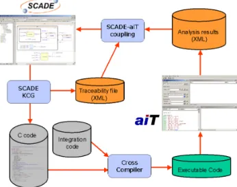
The global workflow for the coupling is pictured in Figure6.
Figure 6: SCADE-aiT workflow
• The SCADE Code Generator generates C code from a SCADE model.
• This code is compiled and linked with user inte-gration code to get an executable.
• aiT performs the WCET analysis on the exe-cutable and produces results for the routines in the executable, which correspond to C functions. The traceability information that is also produced from the SCADE Code Generator provides the de-tailed relation from SCADE operators to generated C functions. This information is used for feeding back WCET results to the SCADE model.
The following issues are detailed in the next sec-tions:
• Integration code generation
• Linking the information between the tools • Reporting the information in the SCADE IDE 4.4 Integration code generation
As expressed in section4.1, there are two different possibilities for the integration code:
1. A simple integration code that is automatically generated;
2. User code defined outside the SCADE environ-ment.
Case 2 requires no special handling. aiT is used on the final executable.
In Case 1, additional C-files are generated from SCADE tools. This is implemented by the “wrap-per” mechanism of SCADE tools, which is a means
to extend the code generation action with other ac-tions, in particular the generation of additional files like “capsule code” that defines a C main() func-tion that calls the SCADE generated code.
As shown in section2, SCADE KCG generates two functions per operator Op:
• Op_reset() that must be called once, before any cycle Op() is executed;
• Op() that performs one execution of the opera-tor.
Usual application code looks like this: main() {
// declarations Op_reset(); while (true) {
//get sensor values Op();
//update actuators }
}
This is a non-ending loop that clearly has no finite WCET and can thus not be analyzed by aiT. There-fore, we generate an alternative code pattern for analysis with aiT. The minimal main code would look like: main() { // declarations Op_reset(); Op(); }
But Op_reset() sets Boolean variables that are later on tested in Op() to distinguish between the first execution of the operator and any subsequent executions, then reset to false in Op().
With the main code proposed above only the “true” part of the conditionals is used in the first execu-tion of Op(), while later execuexecu-tions of Op() in the real application may also use the “false” part. Thus, this simple code can lead to wrong WCET results because aiT recognizes and uses data dependencies between the functions called. Calling Op() a sec-ond time in the “main” wrapper does not solve the problem because in deeper levels of the code, the first execution of an operator with memory can be delayed to several steps from the beginning. To keep the independence between the
Op_reset() and Op() functions and the volatile aspect of input and output contexts and to deter-mine an overall WCET valid for all executions, it is possible to create an analyze function that takes two pointers to contexts, one for the Op_reset() function and the other for the Op() function.
analyze(CtxInType * initInCtx, CtxInType * cycleInCtx, CtxOutType * initOutCtx, CtxOutType * cycleOutCtx) { // declarations
Op_reset (initInCtx, initOutCtx); Op (cycleInCtx, cycleOutCtx); }
Using these contexts it is possible to distinguish be-tween invariant data set in Op_reset() and used in all instances of Op(), and volatile data set in
Op_reset(), but modified in Op() and thus used only in the first instance or first few instances of
Op().
A main function calling the analyze() function is also generated. Finally a complete makefile based on a makefile template provided by the user to set all cross compiler and linker paths and options is generated.
4.5 Linking the information between the tools The results computed by aiT should be mapped back into the SCADE model so that SCADE users can see the results as additional information at the appropriate SCADE operators at the level of the model, without the need to look at the generated C code.
In order to show the SCADE-aiT coupling on a model with more than two operators, the example used hereafter is a car Cruise Control demo exam-ple designed with SCADE.
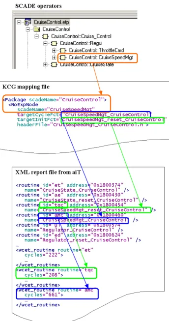
As detailed in previous sections, each SCADE oper-ator is implemented as two C functions, one for the initialization of the operator and one for its normal cyclic execution. Depending on the compiler used or the options given to the compiler, the C func-tion names may not be the same as the SCADE operator names; some compilers for instance put an underscore “_” before the name and /or shorten the identifier. This did not happen in the exam-ple presented in Figure 7; if it happens, an as-sociation between C names and assembly names must be maintained. This is done via a mapping file generated from KCG. In the example of Fig-ure 7, operator CruiseSpeedMgt e.g., is mapped to C functions CruiseSpeedMgt_CruiseControl and CruiseSpeedMgt_reset_CruiseControl. The XML report file produced by aiT contains WCET estimations for assembly routines. The mapping from assembly routine names to times is realized in an indirect way: the XML output file assigns internal identifiers to the routine names; in Figure 7 these are tqc for
CruiseSpeedMgt_reset_CruiseControl and
Figure 7: Linking assembly code to SCADE opera-tors through C code
WCET estimates for these routines can then be found via these routine identifiers (208 cycles for
tqcand 661 cycles for amc).
As shown in Figure7, all the needed information is there to allow a direct feedback from the analysis made on the executable by aiT to the user design in the SCADE IDE.
4.6 Sessions and difference reports
Whatever is the chosen production method for the binary (with auto-generated main and makefile, or using “classical” means), it is interesting to be able to report the effect of changes in the SCADE design and /or in the KCG options. For this, users should be able to handle data obtained from several
differ-ent launches of aiT from the SCADE IDE.
For this reason, we have introduced the concept of sessions. A session is a set of data obtained from one aiT launch. It contains:
• SCADE KCG options, • aiT options,
• WCET data attached to nominal items from the SCADE call graph.
Sessions allow the comparison of WCET results re-sulting from different runs with different SCADE modeling, KCG options, cross-compiler options, and aiT options. Sessions can be selected individually from a panel created in the SCADE IDE.
From the created sessions, the following actions are possible:
• open a session report window (described below), by double-clicking on a session;
• open a diff report by selecting two session items.
Figure 8: WCET analysis report
The session report window (Figure 8) gives an overview of aiT results corresponding to SCADE op-erators to be able to quickly locate bottleneck opera-tors. The SCADE operators are listed in two tables, the first one for cycle functions and the other one
for reset functions. Each may show the following values:
WCET: WCET contribution of the function
with-out descendants. The max, the average, and the sum of the function WCETs computed for indi-vidual calling contexts are given.
CWCET: WCET contribution of the function with
descendants. The max, the average, and the sum of the function WCETs computed for indi-vidual calling contexts are given.
Max Space: The maximum stack usage of the
function without parent stack usage.
CMax Space: The maximum stack usage of the
function cumulated with parent stack usage. The representation allows sorting each column. The report can be customized through an option mechanism offering the possibility to hide some columns (this has been done for the report shown in Figure8).
Each operator definition can be located in the SCADE model by clicking on the “Show in model” icon. A detailed report of a specific SCADE opera-tor can be opened by clicking on the corresponding link in the session report. This detailed report dis-plays the information given by the session report and shows the WCET contribution of each child.
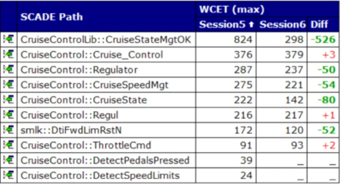
Figure 9: Session diff report
The diff report (Figure9) is structured in the same way as the session report, but for each data, the re-port displays the values for both sessions, and the (absolute and relative) difference between them. The diff report can be customized in the same way as the session report.
The diff report shows precisely, at model level, the effect of the options set for SCADE KCG or the cross compiler. The example from Figure9shows the ef-fect of selecting a higher optimization level in KCG, and inlining two more operators. Improvement is clear for all operators but three whose WCET slightly increased.
5. Evaluation on an industrial model
The technologies presented in this paper have been evaluated on real-size applications. We give here metrics on a Fuel Management Controller for a civil aircraft (more precise information cannot be dis-closed). As a safety-critical application, the code must be certified against DO178B level A; it is a typical application for SCADE design, code being generated by SCADE KCG.
The SCADE model comprises about 80 operators, and the depth of instances reaches 9. The top-level operator has more than 20 inputs, several being rays of 30 elements, and 9 outputs that are also ar-rays and one structure of arar-rays. The model con-tains about 50 iterators, i.e., 50 loops in the gener-ated C code, some being nested loops.
SCADE KCG has been used with different options, in order to examine their influence on the WCET of the application via the diff feature of the SCADE-aiT coupling. If the highest KCG optimization level (level 3) is selected, and all operators are inlined ex-cept for the main 20 top-level operators, 6500 lines of C code are generated. The executable was built with the Wind River Compiler, with standard opti-mization level, for target PowerPC 555.
aiT performed the WCET analysis in 15 seconds, the result being a WCET of 270,000 cycles. With a 40 MHz processor, this gives a WCET of 6.75 ms.
6. Planned Extensions
As described in section2, SCADE 6 unifies dataflow and hierarchical state machines paradigms. For details on the semantics of such a unification, see [1, 2]. Figure 10 gives an example. This model is detailed in the SCADE Language tuto-rial [3]. It is the chronometer part of a standard digital watch model; the Chrono automaton that uses the modCount operator runs in parallel with the Display automaton.
The code generated from SCADE KCG for such a model consists in nested C switches, basically with one case per automata state. C functions are gen-erated only for non-inlined operators. For a model with a hierarchy of several levels of macro-states and dozens or even hundreds of states, aiT com-putes the WCET for the whole operator. In prac-tice the worse case corresponds to one state for each of the parallel automata. If the WCET value must be improved, one needs to know which automaton’s states must be redesigned or split. Generating an aiT parameterization file from the SCADE model, and completing the XML files for the linking oper-ation should allow us to reach this goal.
Figure 10: SCADE Unified Modeling Style
7. Conclusion
Tools based on abstract interpretation can perform static program analysis of embedded applications. Their results hold for all program runs with arbi-trary inputs. Employing static analyzers is thus or-thogonal to classical testing.
Combined with model-based design and automatic code generation, the potential of static analysis tools is increased greatly: More strict specification and development guidelines enforced by tools like SCADE allow for a high precision of the analyzer’s estimates. The resulting combination allows for the development of more secure and better-performing systems while decreasing time-to-market through enhancing development productivity.
For the developer, the immediate and detailed feed-back provided by mapping feed-back aiT’s results into the SCADE IDE helps to find the critical areas of the project where most of the resources are spent. The concept of diff reports also helps to decide be-tween alternatives to solve a given problem. Using model-based design, different modeling techniques can lead to strongly varying code. Here, the
infor-mation provided by aiT can help to prototype and develop software more rapidly.
8. Acknowledgement
The authors acknowledge Jean-Louis Colac¸o, one of the main designers of the SCADE 6 language, who made the first experiments with WCET analysis on code generated from SCADE KCG.
Collaboration between AbsInt GmbH and Esterel Technologies has been supported by the FP6 STREP project INTEREST (INTEgrating euRo-pean Embedded Systems Tools).
9. References
[1] Jean-Louis Colac¸o, Bruno Pagano, and Marc Pouzet. A conservative extension of synchronous data-flow with state machines. In Wayne Wolf, ed-itor, Proceedings of EMSOFT 2005, 5th ACM Inter-national Conference On Embedded Software, pages 173–182. ACM, 2005.
[2] Franc¸ois-Xavier Dormoy. SCADE 6 – A model based solution for safety critical software development. In 4th European Congress ERTS Embedded Real Time Software, Toulouse, France, January 2008.
[3] Esterel Technologies. SCADE language tuto-rial.http://www.esterel-technologies.com, September 2007.
[4] Christian Ferdinand, Reinhold Heckmann, Marc Langenbach, Florian Martin, Michael Schmidt, Henrik Theiling, Stephan Thesing, and Reinhard Wilhelm. Reliable and precise WCET determina-tion for a real-life processor. In Proceedings of EMSOFT 2001, First Workshop on Embedded Soft-ware, volume 2211 of Lecture Notes in Computer Science, pages 469–485. Springer-Verlag, 2001. [5] Christian Ferdinand, Florian Martin, Christoph
Cullmann, Marc Schlickling, Ingmar Stein, Stephan Thesing, and Reinhold Heckmann. New developments in WCET analysis. In Thomas Reps, Mooly Sagiv, and J¨org Bauer, editors, Program Analysis and Compilation, Theory and Practice, volume 4444 of Lecture Notes in Computer Science, pages 12–52. Springer-Verlag, 2007.
[6] Yau-Tsun Steven Li and Sharad Malik. Perfor-mance Analysis of Embedded Software Using Im-plicit Path Enumeration. In Proceedings of the 32nd ACM/IEEE Design Automation Conference, 1995. [7] J¨orn Schneider and Christian Ferdinand. Pipeline
Behavior Prediction for Superscalar Processors by Abstract Interpretation. In Proceedings of the ACM SIGPLAN Workshop on Languages, Compilers and Tools for Embedded Systems, volume 34, pages 35– 44, May 1999.
[8] Henrik Theiling. Extracting Safe and Precise Con-trol Flow from Binaries. In Proceedings of the 7th Conference on Real-Time Computing Systems and Applications, Cheju Island, South Korea, 2000.
[9] Henrik Theiling and Christian Ferdinand. Combin-ing abstract interpretation and ILP for microarchi-tecture modelling and program path analysis. In Proceedings of the 19th IEEE Real-Time Systems Symposium, pages 144–153, Madrid, Spain, De-cember 1998.
[10] Reinhard Wilhelm, Jakob Engblom, Andreas Er-medahl, Niklas Holsti, Stephan Thesing, David Whalley, Guillem Bernat, Christian Ferdinand, Reinhold Heckmann, Tulika Mitra, Frank Mueller, Isabelle Puaut, Peter Puschner, Jan Staschulat, and Per Stenstr¨om. The worst-case execution time problem – overview of methods and survey of tools. ACM Transactions on Embedded Computing Sys-tems, 5:1–47, 2007.

![Figure 4: Phases of WCET computation aiT determines the WCET of a given task in several phases [4] (see Figure 4)](https://thumb-eu.123doks.com/thumbv2/123doknet/14800048.605764/5.892.69.418.683.993/figure-phases-wcet-computation-determines-wcet-phases-figure.webp)