Publisher’s version / Version de l'éditeur:
ASHRAE Transactions, 106, Pt. 1, pp. 605-619, 2000-07-01
READ THESE TERMS AND CONDITIONS CAREFULLY BEFORE USING THIS WEBSITE. https://nrc-publications.canada.ca/eng/copyright
Vous avez des questions? Nous pouvons vous aider. Pour communiquer directement avec un auteur, consultez la première page de la revue dans laquelle son article a été publié afin de trouver ses coordonnées. Si vous n’arrivez pas à les repérer, communiquez avec nous à [email protected].
Questions? Contact the NRC Publications Archive team at
[email protected]. If you wish to email the authors directly, please see the first page of the publication for their contact information.
NRC Publications Archive
Archives des publications du CNRC
This publication could be one of several versions: author’s original, accepted manuscript or the publisher’s version. / La version de cette publication peut être l’une des suivantes : la version prépublication de l’auteur, la version acceptée du manuscrit ou la version de l’éditeur.
Access and use of this website and the material on it are subject to the Terms and Conditions set forth at
Smoke movement for sprinklered fires
Lougheed, G. D.; McCartney, C. J.; Taber, B. C.
https://publications-cnrc.canada.ca/fra/droits
L’accès à ce site Web et l’utilisation de son contenu sont assujettis aux conditions présentées dans le site LISEZ CES CONDITIONS ATTENTIVEMENT AVANT D’UTILISER CE SITE WEB.
NRC Publications Record / Notice d'Archives des publications de CNRC:
https://nrc-publications.canada.ca/eng/view/object/?id=6cc78c81-95db-4344-af95-bbb547b2318c https://publications-cnrc.canada.ca/fra/voir/objet/?id=6cc78c81-95db-4344-af95-bbb547b2318cSmoke movement for sprinklered fires
Lougheed, G.D.; McCartney, C.; Taber, B.C.
Posting courtesy American Society of Heating, Refrigerating and Air-Conditioning Engineers, Inc. www.ashrae.org Originally published in ASHRAE Transactions
Droits d'auteur : affiché avec la permission de l'American Society of Heating, Refrigerating and Air-Conditionning Engineers Inc. www.ashrae.org
Publié à l'origine dans les transactions ASHRAE.
www.nrc.ca/irc/ircpubs
NRCC-43138
ABSTRACT
This paper presents the initial results of a project initiated by the American Society of Heating, Refrigerating and Air-Conditioning Engineers (ASHRAE) and the National Research Council of Canada to investigate smoke movement resulting from a sprinklered fire in a communicating space into an adjacent large open area such as an atrium or retail mall. Recent research on the interaction of sprinkler spray with a smoke layer is also reviewed. In addition, information in the literature from full-scale fire tests of mercantile and office occupancies is discussed.
As part of the joint project, a large-scale test facility was established to investigate smoke flow for sprinklered fires. This facility is described in the paper. The results of steady-state fire tests using a propane burner system are discussed. These tests indicate that two smoke flow regimes can occur depending on the fire size. For fires with low heat release rates, the smoke temperature was uniform over the height of the compartment opening and was near ambient. Under this condition, the smoke was nonbuoyant and accumulated near the opening. With higher heat release rates, a two-zone air and smoke flow regime resulted. The smoke exited the compartment in the hot upper layer. The fire test results were used to determine approx-imate limits for the smoke flow regimes.
Preliminary tests were conducted to investigate the effec-tiveness of opposed airflow systems in limiting smoke flow between the test compartment and the adjacent area. Initial results are also provided for this portion of the investigation.
INTRODUCTION
Design information concerning smoke management for atria and malls is provided in codes and engineering guides
(NFPA 1995; Klote and Milke 1992; Hansel and Morgan 1994; BOCA 1996; ICBO 1994). Although there are differ-ences in the equations used for designing an atrium smoke management system for a fire on the atrium floor, the general approach for atrium smoke management with this fire scenario is similar in each. The atrium smoke management systems rely either on the use of smoke filling the atrium space or the use of smoke ventilation from the hot upper layer to provide a clear height in the atrium for a time period sufficient for occupants to respond and evacuate.
Protecting the occupants of a building from the adverse effects of smoke in the event of a fire is one of the primary objectives of any fire protection system design. Achieving this objective becomes more difficult when dealing with very large spaces, such as an atrium or a mall, where a large number of occupants may be present and the compartment geometries may be complex. Because of these difficulties, model building codes place restrictions on the use of such spaces in buildings. Some of the requirements that are commonly applied in codes include:
• the installation of automatic sprinklers throughout the building,
• limitations on the amount of combustible materials either used in the construction of the building or located on the floor of the atrium, and
• the provision of smoke management systems to main-tain tenable conditions in egress routes.
The requirements for automatic fire suppression and controlling the fuel provide methods to limit the fire size and thus reduce smoke production.
Smoke Movement for Sprinklered Fires
Gary D. Lougheed, Ph.D.
Cam McCartney
Bruce C. Taber
Member ASHRAE
Gary D. Lougheed is a senior research officer and Cam McCartney and Bruce C.Taber are technical officers in the Fire Risk Management
Program, Institute for Research in Construction, National Research Council of Canada, Ottawa, Ontario.
Frequently, in buildings with atria or malls, the commu-nicating spaces (shops, walkways, offices, etc.) open onto the interconnected floor space. There is design guidance provided in engineering guidelines such as NFPA 92B (NFPA 1995) to manage smoke from a fire that originates in a communicating space. One approach is to use the atrium smoke management system to remove any smoke that enters the large, open space to limit the depth of smoke accumulation or delay smoke fill-ing. An alternative approach is to prevent smoke originating in the communicating space from propagating into the large space by using physical barriers or opposed airflow. The limit-ing average velocity required for an opposed airflow system can be calculated using equations developed by Heskestad (1989), which are included in NFPA 92B.
It is assumed in NFPA 92B that it will not be possible to manage smoke within the communicating space without the use of physical barriers to limit smoke movement or methods to limit smoke production, such as controlling the fuel or using automatic sprinklers. Although automatic fire suppression is frequently used to reduce smoke production from fires in a communicating space, there are limited data available on the potential size of sprinklered fires and the transport of smoke cooled by sprinklers. Data such as that produced by Liu (1977) indicates that the smoke from a sprinklered fire may not be buoyant. There are also indications that a sprinklered fire can produce sufficient smoke to result in obscurations that exceed normally accepted tenability limits in the compartment of fire origin (Lougheed 1997).
In 1997, a joint research project was initiated between the American Society of Heating, Refrigerating and Air-Condi-tioning Engineers (ASHRAE) and the National Research Council of Canada (NRC) to investigate smoke movement from a sprinklered fire in a compartment that is allowed to propagate into a large open area (ASHRAE Research Project RP-976). This paper provides initial results from this project, which include a review of previous research on the interaction of sprinkler spray with a smoke layer, heat release rate from sprinklered fires, and smoke movement for sprinklered fires. The large-scale test facility set up to investigate smoke move-ment from a sprinklered compartmove-ment into a large open area is described. Results of tests to determine smoke flow for such fires with and without opposed airflow are discussed.
REVIEW OF SPRINKLERED FIRES
A number of studies have investigated the effects of sprin-klers on the smoke produced by a fire. This includes studies to determine the effects of the sprinkler spray on the hot smoke layer, the heat release rate, and other parameters for sprin-klered fires and smoke movement resulting from a sprinsprin-klered fire. In this section, the research in each of these areas is summarized.
Sprinkler Interaction with the Smoke Layer
Much of the research on the effects of sprinklers on the hot smoke layer has investigated the effects between
sprin-klers and smoke venting in warehouse and industrial applica-tions. McGrattan et al. (1998) and Hinkley et al. (1993a, 1993b) summarize research in this area.
Numerical models were developed for the interaction of sprinkler spray with the hot gases in the smoke layer and in the fire plume (Bullen 1974; Morgan 1979; Alpert 1985; Heske-stad 1991; Cooper 1991; Chow and Fong 1991; Forney and McGrattan 1995). The models generally take into account the convective cooling of the hot layer and the entrainment of hot air in the sprinkler spray.
The research indicates that, prior to control of the fire by the sprinklers, the hot gases in the smoke layer can be entrained by the sprinkler spray, resulting in the smoke layer penetrating into the cold lower layer. However, if the temper-ature of the induced gas flow is above the tempertemper-ature of the cold layer, it will experience a buoyant force, resulting in a reversal of the downward flow (Heskestad 1991). Thus, if the convective cooling by the sprinklers is small relative to the heat content in the hot upper layer, the hot layer will remain buoyant. However, once the sprinklers gain control of the fire, the temperature in the upper layer decreases, leading to a deep-ening of the smoke layer (Morgan 1979). With further decreases in temperature, the buoyancy of the upper layer will decay and the smoke will be transported to the floor and even-tually dispersed throughout the test volume (Heskestad 1991). A limited number of experimental studies were conducted to investigate the cooling of smoke by sprinkler water spray. Liu (1977) investigated the cooling produced by a corridor sprinkler system. In these tests, no sprinklers were included in the burn room. The interaction of the water spray from the corridor sprinkler system on the hot gas flow in the corridor was determined. These tests indicated that the corri-dor sprinkler system was effective in cooling the hot gas flow. In some cases, the smoke temperature exiting the corridor was less than ambient, resulting in nonbuoyant flow.
Morgan and Baines (1979) conducted tests using an exist-ing large-scale test facility, which represented a part of a covered mall. The facility included a store (fire compartment) and a section of an adjacent mall with the sprinkler installed in the latter area. As with the investigations by Liu (1977), these tests determined the heat transfer between the sprinkler spray and the hot gas flow produced by the fire. The results indicated that sprinklers could remove a significant amount of heat and buoyancy from a hot gas layer.
A series of tests were conducted to investigate the cool-ing of a smoke layer by sprinkler spray for a fire in a compart-ment (You et al. 1986, 1989). These tests were conducted in a 3.66 m by 7.32 m by 2.44 m high compartment with a 1.22 m by 2.44 m high opening. A single sprinkler was installed in the test compartment. The fire source was a heptane spray fire with total heat release rates of up to approximately 500 kW. These tests were used to determine empirical correlations for the heat absorption by the sprinkler spray and the rate of convective heat loss through the room opening.
Mawhinney and Tamura (1994) conducted two series of tests using shielded wood crib fires to investigate the interac-tion of sprinklers with the smoke layer in a compartment. The first test series was conducted using a one-story test room and the second was conducted on the seventh floor of a ten-story test facility. In the tests in the one-story room, the center of the wood cribs was shielded from direct impingement by water spray and burning continued in spite of the sprinklers. However, the heat release rate and the temperatures in the test compartment were reduced, with the amount of reduction dependent on the sprinkler application density. At a density of 4.1 L/min per m2, the heat release rate was approximately 850-1200 kW and the temperature near the ceiling was approximately 150°C.
Size of Sprinklered Fires
The performance objective of automatic sprinklers installed in accordance with NFPA 13 (NFPA 1996) is to provide fire control that is defined as follows: limiting the size of a fire by distribution of water so as to decrease the heat release rate and pre-wet adjacent combustibles, while control-ling ceicontrol-ling gas temperatures to avoid structural damage. A limited number of investigations have been undertaken in which full-scale fire tests were conducted in which the sprin-kler system was challenged but provided this level of perfor-mance. The results of these studies are summarized in this section.
There are limited full-scale test data available for use in determining design fire size for sprinklered occupancies. Hansell and Morgan (1994) provide conservative estimates for the convective heat release rate based on U.K. fire statis-tics: 1 MW for a sprinklered office, 0.5-1.0 MW for a sprin-klered hotel bedroom, and 5 MW for a sprinsprin-klered retail occupancy. For the latter case, it was assumed that the fire size is 3 m by 3 m. These steady-state design fires assume the area is fitted with standard response sprinklers.
Full-scale sprinklered fire tests were conducted for open-plan office scenarios (Madrzykowski and Vettori 1992; Lougheed 1997). These tests indicate that there is an exponen-tial decay in the heat release rate for the sprinklered fires after the sprinklers are activated and achieve control. Although a peak heat release rate of approximately 1 MW was measured, the results of these tests indicate that a design fire with a steady-state heat release rate of 500 kW would provide a conservative estimate for a sprinklered open-plan office.
For the open-plan office test (Lougheed 1997), the temperature in the smoke layer in the compartment was quickly reduced to less than 100°C with the operation of the sprinklers. With a shielded fire scenario used in the test arrangement, the smoke initially remained buoyant after sprinkler operation. However, as the fire decayed, the smoke lost its buoyancy and was mixed throughout the fire compart-ment.
Full-scale fire tests for retail occupancies were conducted in Australia (Bennetts et al. 1997). These tests indicated that
for many common retail areas (clothing and bookstores), the fire was controlled and eventually extinguished with a single sprinkler. However, tests simulating areas with shielded fire loads did result in large fires. This includes tests simulating a fire in a toy store and in a storage area for a shoe store. Only four active normal response sprinklers were installed for these tests with a water flow rate of approximately 91 L/min per sprinkler with four sprinklers operating.
The toy store had predominantly plastic combustibles arranged in high shelving. The ignition source was located away from the sprinklers to minimize direct impingement on the fire during the initial fire growth. With this scenario, the fire continued to spread along the shelving but did not spread to other racks. The sprinklers limited the temperatures at the ceiling and at the edge of the test structure. The temperature of the smoke leaving the test area was generally less than 100°C compared to more than 1000°C for the nonsprinklered test. The smoke remained buoyant. The temperature at the ceiling of the test facility was less than 40°C compared to 320°C for the nonsprinklered test.
For the tests simulating the shoe store storage area, the shelves were spaced much closer together than for the toy store. The spacing and height of the shelving met Australian standards. However, based on water spray tests, minimal water would reach the base of the test arrangement.
In both the sprinklered and nonsprinklered tests, the fire took a considerable time (10 to 30 minutes) to develop. Once fully developed, the four activated sprinklers were not able to fully control the fire. However, they did substantially reduce the temperatures in the test structure and at the ceiling of the main test facility (145°C versus 360°C for the nonsprinklered test). Also, the temperature in the vicinity of the sprinklers was 200°C-250°C, suggesting that more sprinklers would have activated in a real fire situation.
Full-scale fire tests were conducted for a variety of occu-pancies (retail, cellular offices, and libraries) in the U.K. (Ghosh 1997). The retail fire simulations included supermar-ket displays, carpet displays, video stores, and liquor stores. For these tests, the sprinklers controlled the fire. The shelving sheltered the fuel and the fire could continue to spread along the shelves. However, the sprinklers did decrease the temper-ature of the gases, reducing the convective portion of the heat release rate from the test area to 30%-50% of the total heat release rate compared to 65%-75% for nonsprinklered tests. The convective heat release rate per unit area for sprin-klered fires varied from 150 kW/m2 to 650 kW/m2. This indi-cates that the use of a constant 500 kW/m2 convective heat release rate for sprinklered fires as suggested by Hansell and Morgan (1994) may not always be justified (Ghosh 1997).
Full-scale fire tests were conducted for compact mobile storage systems used for document storage (Lougheed et al. 1994). Such systems are frequently used in a variety of appli-cations including libraries, offices, and hospitals. Information on tests conducted in 1979 on behalf of the Library of Congress is provided in Appendix G of NFPA 910 (NFPA
1991). Subsequent full-scale fire tests were conducted for the Library of Congress Archives II and the National Library of Canada and showed that fires in compact mobile systems are difficult to extinguish and large quantities of smoke could be produced even after sprinkler activation (Lougheed et al. 1994).
The results of the research summarized in this section indicate that, for a fire control situation, the heat release rate is reduced but smoke can continue to be produced. The temperature of the smoke is also reduced. The smoke was buoyant, at least in the initial stages of tests with larger fire sizes. However, once the sprinklers begin to suppress the fire, the smoke can become nonbuoyant and remain at floor level.
Smoke Movement for Sprinklered Fires
There are very limited test data providing information on smoke movement to areas outside the fire zone for sprinklered fires. However, some studies do provide useful information. These studies are summarized in this section.
As part of an extended study on fires in patient rooms of health care facilities, 21 full-scale fire tests were conducted at the U.S. National Institute of Standards and Technology. These tests involved either a mattress with bedding or a clothing wardrobe. Under nonsprinklered conditions, the combustible clothing wardrobe fire resulted in room flash-over in 120 seconds and rapid development of a smoke layer in the room and adjoining corridor with smoke obscuration and CO concentrations exceeding tenability levels through-out the test area (O’Neill et al. 1980).
In subsequent tests with standard 71°C pendent sprinklers arranged to provide a 6.9 (L/min)/m2 application density, the ceiling gas temperature was lowered. However, the fire could still be seen burning inside the wardrobe until smoke obscured visibility 60 seconds after the activation of the sprinkler. Also, very high concentrations of CO were measured at the 1.5 m height throughout the test area with the instantaneous hazard-ous threshold of 1% exceeded in the patient room, the corridor, and the remote lobby area.
In tests with the same wardrobe fire scenario using a stan-dard 71°C horizontal sidewall sprinkler arranged to provide the same application density as the pendent sprinkler, better fire control was obtained. CO concentrations were signifi-cantly lower.
As part of the research on shielded wood crib fires, Mawhinney and Tamura (1994) investigated smoke move-ment in a ten-story test facility set up to simulate a building with zoned smoke control. The smoke control system prevented smoke spread to adjacent pressurized floors. However, the smoke could spread into the stairshaft if the door to the fire floor was open. By opening the doors to the stair-shaft on other floors or to the exterior, the stairstair-shaft could be pressurized, reducing the smoke flow into the stairshaft. Also, with the zoned smoke control system shut off, the buoyancy pressures were sufficient to cause smoke spread into adjacent areas.
Lougheed and Carpenter (1997) investigated smoke movement into a corridor and subsequently into a stair shaft using a ten-story test facility. The fire scenario was similar to those used in a series of sprinklered open-plan office tests (Lougheed 1997). Differences in sprinkler operation during the initial stage of the tests had an impact on the smoke temper-ature in the corridor and thus on the extent and rate at which smoke spread in the test facility. Shortly after sprinkler acti-vation, the temperature and CO concentrations measured at various locations in the corridor did not vary substantially with height, indicating minimal smoke stratification once the sprin-klers began to suppress the fire.
Review Summary
The available information on the interaction of sprinkler spray on a smoke layer, the size of sprinklered fires, and smoke movement into adjacent areas for a sprinklered fire were reviewed in this section. Although the research in this area is limited, some general trends can be determined.
1. The size of a fire will be limited by the sprinklers, assuming the sprinkler system meets its design objective. However, during the fire control phase, a fire can continue to burn, producing smoke. The size of the sprinklered fire depends on the occupancy (the typical fuel load) and the ability of the sprinkler spray to reach the seat of the fire (shielding effects of furnishing, shelving, etc.). An analysis of U.K. fire statistics indicates that the major effect of sprinklers is to reduce the probability of a sprinklered fire reaching a given size compared to the equivalent nonsprinklered case (Morgan 1998). For example, approximately 7% of fires in sprinklered public-access areas and 13% of fires in sprin-klered non-public areas of retail occupancies will exceed a fire damage area of 10 m2.
2. For office occupancies, the fire size in office areas is limited to 1 MW or less. A steady 500 kW fire would provide a conservative design fire. However, assuming an exponen-tial decay in fire size provides a more accurate representa-tion of the suppression phase. The potential fire size in document and other storage areas has not been determined. However, there are indications that a substantial sprinklered fire could develop in such areas (Lougheed 1997). 3. For retail occupancies, the fire size will depend on the use
of the space. Based on a review of U.K. fire statistics, a conservative design fire of 5 MW has been used extensively for design purposes. There are, however, indications that the 5 MW design fire size is conservative for many appli-cations (Ghosh 1997). Tests simulating fires in clothing stores, which generally constitute a high proportion of the floor area in modern shopping centers, were suppressed by the sprinklers (Bennetts et al. 1997). However, there are other areas in retail facilities in which there can be substan-tial fire loads shielded from direct water spray and in which larger fires may occur (Ghosh 1997; Bennetts et al. 1997). Considering the broad range of use of non-public retail
areas, it is difficult to develop a single design fire, and further work is required to develop a range of representative design fires (Ghosh 1997).
4. During the early stages of a sprinklered fire, the water spray will cool the hot layer. However, the smoke will generally remain buoyant until the sprinklers begin to suppress the fire (Heskestad 1991). This smoke will rise above floor level once it exits the sprinklered area (Bennetts et al. 1997). 5. With fire suppression, the smoke layer is rapidly cooled and it will lose its buoyancy. During this stage, the smoke will be distributed over the entire height of the compartment (Heskestad 1991; Lougheed 1997). A similar result can also occur if there is cooling by water spray from sprinklers in adjacent areas (Liu 1977). The conditions under which the transition between buoyant and nonbuoyant smoke flow occurs was investigated in the full-scale tests discussed in this paper.
6. The temperature of the smoke outside the fire zone is dependent on a combination of parameters, such as the heat release rate of the fire and the sprinkler spray density (Mawhinney and Tamura 1994). However, there are very limited data available upon which to determine the convec-tive heat content and, thus, the temperature of the smoke leaving the sprinklered area. For design purposes, it can be assumed that the maximum temperature of the smoke exit-ing a sprinklered fire area is approximately the activation temperature of the sprinklers (Morgan and Gardiner 1990). If the smoke temperature substantially exceeds this temper-ature, further sprinklers will be activated, resulting in a cooling of the smoke layer. The various parameters that affect the smoke temperature exiting the fire zone are discussed in this paper.
7. There is very limited information available on smoke movement external to the fire zone. Under some test
condi-tions, the CO concentrations and smoke obscuration in adjacent areas exceeds generally accepted tenability limits (Mawhinney and Tamura 1994; Lougheed and Carpenter 1997). There are also indications that the extent and rate of smoke spread for sprinklered fires is dependent on the temperature of the smoke leaving the fire area (Lougheed and Carpenter 1997).
DESCRIPTION OF EXPERIMENT
A large-scale test facility was set up to investigate the impact of sprinklers on smoke movement from a compartment into a large adjacent area. This facility was used to conduct a series of tests with propane-fueled fires to determine the parameters that affect the smoke temperature.The parameters that determine whether the smoke will be buoyant or nonbuoy-ant were also investigated. Tests were also conducted to deter-mine the ability of opposed airflow systems to limit smoke flow through the opening in the test compartment. Tests simu-lating retail fire situations are planned for the second phase of the project. The results of these tests will be discussed in a subsequent paper. A description of the large-scale test facility is provided in this section.
Test Facility
The test facility setup for this project made use of a large-scale atrium physical model used for a previous joint project between ASHRAE and NRC (ASHRAE Research Project RP-899). Detailed information on the atrium physical model is provided in the paper by Lougheed et al. (1999). The atrium facility had a floor area of 13.1 m by 17.2 m and a height of 12.2 m.
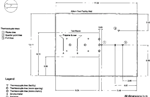
For the present test series, a test compartment was constructed inside the atrium facility. A plan and elevation view of the atrium test facility are shown in Figures 1 and 2.
The test compartment was a two-story steel structure with a floor area of 5.2 m by 9.2 m and an overall height of 6.4 m. A secondary floor was installed at the 3.39 m height to provide a raised test compartment simulating a retail space on an upper level of a retail mall. This compartment was used for all the tests discussed in this paper and had a floor to ceiling height of 3.01 m. Plan and elevation views of the test compartment are shown in Figures 3 and 4, respectively.
Three walls of the test compartment were lined with 18 gauge galvanized steel sheets. The fourth side, located at the center of the atrium facility, was open to provide ventilation to the fire and to allow the smoke produced by the fire to enter the large secondary test space. The test arrangement was such that
the centerline of the open wall in the test compartment was at the center of the atrium facility (Figures 1 and 2).
For most of the tests, the opening was the full height of the compartment, allowing the smoke produced by the fire to flow along the ceiling of the compartment and into the adjacent test area. The opening was 5.0 m wide by 3.01 m high.
Selected tests were conducted with a 0.6 m deep soffit at the top of the opening simulating the case in which the door opening between the communicating space and the mall does not extend to the ceiling. For these tests, the ing was 5.0 m wide by 2.4 m high. The tests with this open-ing arrangement also investigated the effects of the development of a contained hot layer in the test compart-ment on the smoke exiting the test compartcompart-ment.
Figure 2 Large scale atrium facility and instrumentation (elevation).
Instrumentation
Thermocouple trees were located in the test compartment and the atrium facility. The locations of the thermocouple trees in the atrium facility are shown in Figures 1 and 2. The plume thermocouple tree (Location 1) and the quarter point thermocouple tree (Location 2) were used for the tests discussed in this paper. The plume thermocouple tree was located 0.5 m from the test compartment (Figure 1) and on the centerline of the opening in the compartment. The quarter point thermocouple tree was located at the northeast quarter point of the atrium facility. For both thermocouple trees, the spacing between thermocouples was 0.5 m starting at a height of 0.69 m and 3.2 m above the floor of the main test facility for the plume and quarter point thermocouple trees, respectively. Three thermocouple trees were installed in the opening in the compartment (Figures 3 and 4). These thermocouple trees were located at the ¼ width, the center, and the ¾ width of the opening. Six thermocouples spaced at 450 mm were installed on each tree starting at a height of 730 mm above the floor of the compartment. The top thermocouples were 2.98 m above the floor and approximately 30 mm below the ceiling of the compartment.
Two thermocouple trees, with six thermocouples on each tree, were located inside the test compartment (Figures 3 and 4). These thermocouple trees were located on the centerline of the compartment 3.04 and 6.24 m from the compartment opening. The thermocouples were spaced at 500 mm starting 400 mm above the compartment floor.
Thin metal shields were installed above the thermocou-ples on the trees inside the test compartment and in the open-ing. These shields were 230 mm in diameter and minimized direct water spray from the sprinklers reaching the thermo-couples. It was shown in a previous test program (Lougheed 1997) that such shields are effective in minimizing the cooling
of the thermocouples by the water spray, allowing the temper-ature of the air to be measured.
In addition to the room and opening thermocouple trees, thermocouples were also installed adjacent to each of the four sprinklers in the test compartment (Figures 3 and 4).
Two smoke meters were located in the atrium facility near the compartment opening (Figures 1 and 2). These smoke meters were located 3.5 m from the test compartment at the centerline of the opening and were 1.7 m and 3.7 m above the floor of the main test facility. They were used to determine if the smoke exiting the test compartment was nonbuoyant, resulting in downward smoke flow.
Two video cameras were located in the atrium facility. One camera was on the south wall viewing the fire inside the test compartment. The second camera was mounted on the east wall at the same height as the top of the compartment opening and was used to obtain video records of the smoke plume as it exited the test compartment. Video records were also taken of smoke conditions at floor level.
Propane Burner Fire Source
A propane burner was used as the fire source for the majority of the tests discussed in this paper. Propane was provided through a T-connection located at the center of a 2.7 m long, 50 mm I.D. steel pipe. The pipe was capped at both ends. Two rows of 70 equispaced 4.7 mm diameter holes were located in the bottom section of the pipe. The pipe was mounted 410 mm above the floor and was shielded by a 1.23 m wide by 2.45 m long metal table. The top of the table was 640 mm above the pipe.
Rotameters were mounted in the propane line, which fed the propane from the main propane tanks to the burner. Three rotameter sets with ranges of 62-624, 131.1-1311, and 245.5-2455 standard L/min were used in series and provided
measurements over the complete range of flow rates used in the test series. The propane flow rate was used to estimate the heat release rate using the measured heat of combustion for the propane.
The propane burner was used to conduct a series of steady-state fire tests. For each test, the propane flow rate was set at an initial level. Sufficient time was allowed for condi-tions in the compartment to come to steady state. The propane burner was subsequently adjusted to higher flow rates with sufficient time allowed at each step to obtain steady condi-tions. In this way, conditions in the test compartment could be determined for several heat releases under the same test condi-tions.
Sprinkler System
A sprinkler system with four pendent sprinklers was installed in the test compartment. The location of the klers is shown in Figure 3. The protection area for each sprin-kler was 12 m2 to simulate a sprinkler system in an ordinary hazard occupancy. The distance between the two branch lines was 4.6 m, which is the maximum spacing allowed for an ordi-nary hazard occupancy. The sprinkler spacing on each branch line was 2.6 m. The sprinklers were 2.3 m from the back wall of the test compartment and 1.3 m from the sidewalls.
Tests were conducted with the propane burner at two loca-tions in the test compartment. One series of tests was conducted with the burner 1.6 m from the back (north) wall of the test compartment (Location A in Figure 3). This simulated a fire near a wall with the hot gases exiting through the sprin-kler spray. Tests were conducted with two and four operating sprinklers.
The second series of tests was conducted with the propane burner located midway between the two sprinkler branches (Location B in Figure 3). This simulated a fire in the central area of a room with the nearest four sprinklers activated.
Tests were conducted with three water flow rates selected to provide an application density of 4.1, 6.1, and 8.1 (L/min)/m2, which covers the design range in NFPA 13 (NFPA 1996) for ordinary hazard occupancies. A pressure gauge was installed in the main sprinkler pipe and was used to monitor the water flow rate during a test.
A thermocouplewas installed in the sprinkler pipe and the temperature of the sprinkler water was recorded throughout a test. The water for the sprinkler system was obtained from a cistern located below the test facility. The water temperature was constant throughout a test. The water temperature was, however, dependent on the time of year in which the test was conducted. It varied between 12°C and 16°C.
Fan System for Opposed Flow Tests
To simulate opposed airflow systems, mechanical exhaust systems were connected to the back wall of the test compartment. One portion of the system used two nominal 2.8 m3/s fans connected through 460 mm diameter ducts to six exhaust inlets in the test compartment. The exhaust inlets
were 0.85 m from the sidewalls and were centered 0.29 m, 1.34 m, and 2.77 m above the compartment floor. The second portion of the system used a nominal 7.1 m3/s fan connected to two 610 mm diameter exhaust inlets located at the center of the wall of the compartment. The exhaust inlets were centered 1.34 m and 2.67 m above the compartment floor.
Tests were conducted with three fan/inlet arrangements: 1. The two small fans operating using the two mid-height
inlets with a total fan capacity of 5.6 m3/s.
2. Three fans operating using the highest inlets with a total fan capacity of 12.7 m3/s.
3. Three fans operating using the three mid-height inlets with a total fan capacity of 12.7 m3/s.
Test Parameters
Approximately 50 tests covering 125 test conditions were conducted with the propane burner fire source to investigate the impact of various parameters. The parameters included 1. location of the fire (Location A and B in Figure 3), 2. heat release rates (150, 200, 250, 300, 400, 500, 600, 750,
1000, 2000, 3000 kW),
3. number of sprinklers operating (two and four),
4. sprinkler application density (4.1, 6.1, and 8.1 (L/min)/m2), 5. with opposed airflow at different flow rates,
6. with and without soffit at the top of the compartment open-ing.
PROPANE BURNER TEST RESULTS Smoke Flow Tests
Each fire test consisted of a series of steady-state fires. The other parameters, including the sprinkler flow rate, remained constant.
During each stage of the test, the propane flow rate and thus the total heat release rate were maintained steady for sufficient time for the temperature conditions in the test compartment to stabilize. Figure 5 shows the temperature measured at a thermocouple tree in the compartment open-ing for a typical test. The heat release rates were 1000, 2000, and 3000 kW and the sprinkler application density was 6.1 (L/min)/m2. With each change in heat release rate, the temperatures measured in the compartment opening quickly adjusted to relatively constant levels. A similar result was also noted for the temperatures measured inside the compartment.
The temperature data were used to determine an average temperature at each thermocouple location to develop temper-ature versus height profiles for the steady-state conditions. Since there is no provision for conditioning the environment in the test facility, the ambient temperature varied between 10°C and 30°C depending on the time of year. To simplify the comparison of temperature profiles between tests, the ambient temperature was subtracted from the measured temperature.
The results were plotted as temperature rise versus height profiles.
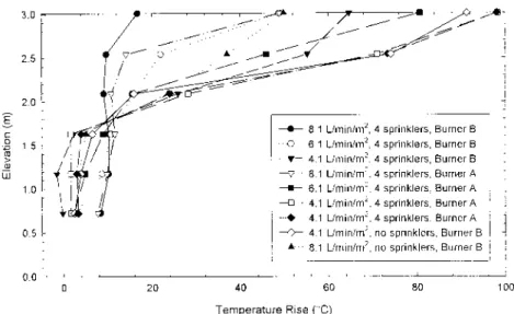
The temperature profiles obtained at the three-thermo-couple locations in the compartment opening for a series of tests at 500 kW are shown in Figure 6. The temperature profiles are similar at each location except for small varia-tions. These differences are most likely due to the dynamics produced in the compartment by the fire and sprinkler spray. Since the temperature variation across the compart-ment opening was minimal, the profiles at the three compartment opening locations were averaged to produce a series of composite temperature rise versus height profiles. Temperature rise profiles are shown in Figures 7-9 for tests conducted with the two locations for the propane burner and three sprinkler application densities with four operat-ing sprinklers. The heat release rates were 250, 1000, and 2000 kW. The temperature profile for tests without sprin-klers is also shown in Figure 7. In addition, the results for tests conducted at 1000 kW with two sprinklers are shown in Figure 8.
As shown in Figures 7-9, the burner location, the number of operating sprinklers, and the sprinkler application density impacted on the temperature rise in the smoke exiting the test compartment. The variations in the profiles were consistent with those expected with convective cooling of the smoke by the sprinkler spray. These include
1. a reduction in temperature for tests with four operating sprinklers compared to two sprinklers,
2. a reduction in temperature for tests with the burner located at the back of the compartment compared with the middle of the compartment, and
3. a systematic decrease in the temperature with sprinkler application density.
Although there may be some reduction in the amount of propane fuel burned, the test results indicate that suppression of the fire by the sprinklers was minimized. By using a shielded propane burner, the smoke flow tests were focused on the impact of the water spray from the sprinklers on the smoke produced by the fire. The differences in the temperature rise profiles are indicative of the changes in convective heat in the smoke layer exiting the compartment with changes in test parameters.
Temperature rise versus heat release rate at the six eleva-tions in the compartment opening are shown in Figures 10 and 11 for sprinkler flow rates of 4.1 and 8.1 (L/min)/m2, respec-tively. In all cases, the burner was located at the back of the compartment. The test results indicate that there were three smoke flow regimes with the sprinklered fires:
1. If the convective cooling of the smoke by the sprinklers was small compared to the convective heat produced by the fire, the predominant smoke flow is in a hot upper layer. The depth of this layer remained relatively constant at approxi-mately 1 m. The temperature in the lower portion of the opening was near ambient. The airflow in this region was predominantly into the compartment to provide combus-tion air.
Figure 5 Temperature profiles for thermocouples in the compartment opening for test with heat release rates of 1000, 2000, and 3000 kW and a 6.1 (L/min)/m2 sprinkler application density.
Figure 6 Temperature profiles at three locations in the compartment opening for tests at 500 kW.
Figure 8 Average temperature profiles in opening for tests at 1000 kW.
Figure 9 Average temperature profiles in opening for tests at 2000 kW.
2. If the convective cooling of the smoke by the sprinklers was high compared to the convective heat produced by the fire, a hot upper layer was not formed. The temperature was uniform over the height of the compartment opening. The temperature was slightly above ambient.
3. For intermediate heat release rates, there was a transition zone in which a hot layer formed at the ceiling and there was also a mixture of cold smoke in the lower layer. With increasing heat release rate, there was a shift to the two-zone flow regime as the temperatures increased in the upper layer and decreased to near ambient in the lower portion of the compartment.
Using the temperature rise versus heat release rate data, approximate upper and lower limits can be estimated for the three smoke flow regimes. The results are shown in Table 1. The criteria used to select the two limits are as follows: 1. The upper limit to the cold smoke flow regime was the heat
release rate above which the temperature at ceiling level was higher than at the lower levels.
2. The lower limit for the two-zone flow regime was the heat release rate above which the temperature at 0.73 m height began to decrease.
The potential for the smoke produced by the fire to impact on life safety is different in the two smoke flow regimes: 1. Cold Smoke Flow: The smoke temperature was close to
ambient and the smoke flow from the compartment was over the total height of the opening. As a result, the smoke meters located in the large space measured smoke obscura-tion, indicating there was a potential for reduced visibility. However, with the reduced temperature, the flow velocity was reduced, which may provide sufficient time for occu-pants to safely evacuate from the fire area.
2. Two-Zone Smoke Flow: With higher heat release rates, a hot
upper layer developed in the test compartment and the smoke flow from the test compartment into the adjacent space was predominantly in the upper hot layer. The sprin-klers reduce the convective heat content in the hot layer. However, they do not reduce the mass flow rate through the opening (Morgan and Gardiner 1990). Further tests are planned to determine the smoke-filling rate in the adjacent space for fire scenarios that produce smoke flow in this regime.
Opposed Air Flow Tests
A method for determining the air velocity through the opening to a communicating space to limit smoke originating in the communicating space from propagating into the large space is provided in NFPA 92B (NFPA1995). The limiting velocity is calculated using the following equation:
v = 0.64 [gH (Tf− To) / Tf]1/2 (1) where
v = air velocity (m/s),
g = acceleration of gravity (9.8 m/s2),
TABLE 1
Heat Release Rate Limits Smoke Flow Regimes
Sprinkler Application Density ((L/min)/m2) Burner Location Upper Limit Cold Smoke Regime (kW) Lower Limit Two-Zone Regime (kW) 4.1 Middle <150 150 4.1 Back <150 300 6.1 Middle 200 750 6.1 Back 300 750 8.1 Middle 500 750 8.1 Back 800 1000
H = height of the opening (m),
Tf = temperature of heat smoke (K),
To = temperature of ambient air (K).
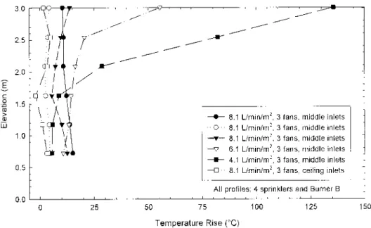
Preliminary tests were conducted with the fan systems described in this paper. All the tests were conducted with the full compartment opening. The estimated average velocity through the opening using the two small fans with a total capacity of 5.6 m3/s was 0.37 m/s. With the three fans operat-ing with a total capacity of 12.7 m3/s, the estimated velocity was 0.85 m/s.The flow rates produced using the three-fan system should be effective for low heat release fires in which the temperature rise is less than 20°C.
Figure 12 shows the average temperature measured in the compartment opening for tests conducted at 500 kW. For these tests, the burner was located at the middle of the compartment and four sprinklers were used. The results indicate that the smoke had to be relatively cool for the opposing airflow to completely reduce smoke flow through the opening. With lower sprinkler application densities, there was sufficient temperature in the hot layer to result in smoke flow through the opening.
There are indications that improved performance was obtained in tests with the exhaust inlets located in the upper portion of the compartment, resulting in direct exhaust from the smoke layer. However, the tests conducted thus far are at the lower operating limits of such a system. Tests are planned with the compartment opening partially blocked to provide increased airflow through the opening. These tests will provide a better indication of the range of performance for the opposed air flow system.
CONCLUSIONS
This paper provides initial results of a joint ASHRAE and NRC research project to investigate smoke flow into a
large-volume space as a result of a sprinklered fire in an adjacent compartment.
The recent literature on the effects of sprinkler spray on smoke flow is reviewed. The research in this area is limited, with much of the work related to the interaction between sprin-klers and building vents. However, there were indications that a hot smoke layer will be maintained until the sprinklers begin to suppress the fire. This observation is consistent with the results obtained in the propane burner fire tests conducted in the full-scale test facility, which are described in this paper. Specifically, if the heat release rate exceeded a lower limit, the smoke flow through the compartment opening was predomi-nantly in a hot layer in the upper portion of the opening.
Based on the test results, approximate heat release rate limits were determined above which hot smoke flow was predominant for the test conditions. The limits were depen-dent on fire location and sprinkler application density ranging between approximately 150 kW to 750 kW for 4.1 (L/min)/m2 and 8.1 (L/min)/m2, respectively.
With increasing heat release rates, there was a steady increase in the temperatures measured in the upper layer. However, for high heat release rates, the temperature near the ceiling exceeded 100°C, and further sprinklers would be expected to operate in a real fire, cooling the upper layer (Morgan and Gardiner 1990). The limits within which further sprinklers might operate in the test configuration ranged from approximately 1500 kW for the low sprinkler application density to approximately 2500 kW for the high sprinkler appli-cation density. This is within the range of fire sizes that could be expected in retail occupancies with high fire loads (Ghosh 1997; Bennetts et al. 1997). Further fire tests are planned to assess the smoke flow with realistic fire scenarios and the potential smoke filling in the adjacent large space.
For low heat release rate fires (<800 kW), the smoke was evenly distributed over the height of the compartment open-ing. Under such conditions, the smoke had limited buoyancy and would accumulate near the opening. This result is consis-tent with observations in the literature (Heskestad 1991; Liu 1977; Bennetts et al. 1997). Such smoke could result in a loss of visibility for occupants. However, the cold nonbuoyant smoke flow regime generally occurs near the end of the fire incident as the sprinklers begin to suppress the fire (Heskestad 1991; Lougheed 1997). By this time, most occupants should have evacuated the fire area. Tests simulating fires in mercan-tile occupancies are planned for the second phase of the project to investigate the potential impact on life safety.
Initial tests were conducted to evaluate the effectiveness of opposed airflow in limiting smoke produced by a compart-ment fire from entering the adjacent space. All the tests conducted thus far were with the full compartment opening with a maximum fan capacity of 12.7 m3/s. This provided an average velocity through the opening of 0.85 m/s. Even with these low air velocities, the tests conducted thus far indicate that the system may be effective if the smoke is sufficiently cooled by the sprinklers. A further test series is planned in which the size of the compartment opening is reduced to increase the airflow velocity.
REFERENCES
Alpert, R.L. 1985. Numerical modeling of the interaction between automatic sprinkler sprays and fire plumes.
Fire Safety Journal 9: 157-163.
Bennetts, I.D., M. Culton, M.L. Dickerson, R. Lewins, K.W. Poh, S.L. Poon, R. Ralph, A.C. Lee, P.F. Beever, R.J. Cooper, P.I. Haggar, I.P. Moore, G.C. Ramsay, and G.R. Timms. 1997. Simulated shopping centre fire tests, BHPR/SM/R.G/062. Australia: Broken Hill Proprietary Company Limited.
BOCA. 1996. The BOCA National Building Code. Country Club Hills, Ill: Building Officials and Code Administra-tors International Inc.
Bullen, M.L. 1974. The effect of a sprinkler on the stability of a smoke layer beneath a ceiling. Fire Research Note
No. 1016, Garston, U.K.: Building Research
Establish-ment.
Chow, W.K., and N.K. Fong. 1991. Numerical simulation on cooling the fire-induced air flow by sprinkler water sprays. Fire Safety Journal 17: 263-290.
Cooper, L. 1991. Interaction of an isolated spray and a two-layer compartment fire environment. NISTIR 4587. Gaithersburg, Md.: National Institute of Standards and Technology.
Forney, G.P., and K.B. McGrattan. 1995. Computing the effects of sprinkler sprays on fire induced gas flow.
Pro-ceedings, International Conference on Fire Research and Engineering. Orlando: Society of Fire Protection
Engineers.
Ghosh, B.K. 1997. Fires in real scenarios. International
Symposium on Fire Science and Technology, ISFST 1997, Seoul, Korea, p. 439-447.
Hansell, G.O., and H.P. Morgan. 1994. Design approaches for smoke control in atrium buildings, BR-258. Garston, U.K.: Building Research Establishment.
Heskestad, G. 1989. Inflow of air required at wall and ceiling apertures to prevent escape of fire smoke. FMRC J.I.0Q4E4.RU. Norwood, Mass.: Factory Mutual Research Corporation.
Heskestad, G. 1991. Sprinkler/hot layer interaction. NIST-GCR-91-590. Gaithersburg, Md.: National Institute of Standards and Technology.
Hinkley, P.L., G.O. Hansell, N.R. Marshall, and R. Harrison. 1993a. Large-scale experiments with roof-vents and sprinklers. Part 1, Temperature and velocity measure-ments in immersed ceiling jets with a simple model.
Fire Science and Technology 13: 19-41.
Hinkley, P.L, G.O. Hansell, N.R. Marshall, and R. Harrison. 1993b. Large-scale experiments with roof-vents and sprinklers. Part 2, The operation of sprinklers and the effects of venting with growing fires. Fire Science and
Technology 13: 43-59.
ICBO. 1994. The Uniform Building Code. Whittier, Calif.: International Conference of Building Officials.
Klote, J.K., and J.A. Milke. 1992. Design of smoke
manage-ment systems. Atlanta: American Society of Heating,
Refrigerating and Air-conditioning Engineers.
Liu, S.T. 1977. Analytical and experimental study of evapo-rative cooling and room fire suppression by corridor sprinkler system. NBSIR 77-1287. Gaithersburg, Md.: National Institute of Standards and Technology. Lougheed, G.D., J.R. Mawhinney, and J. O’Neill, J. 1994.
Full-scale fire tests and the development of design crite-ria for sprinkler protection of mobile shelving units. Fire
Technology 30: 98-133.
Lougheed, G.D. 1997. Expected size of shielded fires in sprinklered office buildings. ASHRAE Transactions 103 (1): 395-410.
Lougheed, G.D., and D.W. Carpenter. 1997. Full-scale fire tests for sprinklered offices in a high rise building,
Pro-ceedings Second International Conference on Fire Research and Engineering, Gaithersburg, Md., pp.
475-486.
Lougheed, G.D, G.V. Hadjisophocleous, C. McCartney, and B.C. Taber. 1999. Large-scale physical model studies for an atrium smoke exhaust system. ASHRAE
Transac-tions, 105 (1): 676-698.
Madrzykowski, D., and R. Vettori. 1992. A sprinkler fire suppression algorithm. J. of Fire Prot. Engr. 4: 151-164. Mawhinney, J.R., and G.T. Tamura. 1994. Effect of auto-matic sprinkler protection on smoke control systems.
ASHRAE Transactions 100 (1): 494-513.
McGrattan, K.B., A. Hamins, and D.W. Stroup. 1998. Inter-national fire sprinkler; smoke and heat vent; Draft
cur-tain fire test project—Large scale experiments and model development. Quincy, Mass.: National Fire Pro-tection Research Foundation.
Morgan, H.P. 1979. Heat transfer from a buoyant smoke layer beneath a ceiling to a sprinkler spray. 1. A tenta-tive theory. Fire and Materials 3: 27-32.
Morgan, H.P. 1998. Sprinklers and fire safety design. Fire
Safety Engineering 5: 16-21.
Morgan, H.P., and K. Baines. 1979. Heat transfer from a buoyant smoke layer beneath a ceiling to a sprinkler spray. 2. An experiment. Fire and Materials 3: 34-38. Morgan, H.P., and J.P. Gardiner. 1990. Design principles for
smoke ventilation in enclosed shopping centres. BR 186. Garston, U.K.: Building Research Establishment. NFPA. 1991. NFPA 910, Recommended practice for the
pro-tection of libraries and library collections. Quincy,
Mass.: National Fire Protection Association.
NFPA. 1995. NFPA 92B, Guide for smoke management
sys-tems in malls, atria, and large areas. Quincy, Mass.:
National Fire Protection Association.
NFPA. 1996. NFPA 13, Standard for the installation of
sprinkler systems. Quincy, Mass.: National Fire
Protec-tion AssociaProtec-tion.
O’Neill, J.G., W.D. Hayes, and R.H. Zile. 1980. Full-scale fire tests with automatic sprinklers in a patient room, Phase II. NBSIR 80-2097. Gaithersburg, Md.: National Institute of Standards and Technology.
You, H.-Z., H.-C. Kung, and Z. Han. 1986. Spray cooling in room fires. NBS-GCR-86-515. Gaithersburg, Md.: National Institute of Standards and Technology.
You, H.-Z., H.-C. Kung, H.-C., and Z. Han. 1989. The effects of spray cooling on the ceiling gas temperature at the door opening of room fires. Fire Safety Science,
Pro-ceedings of the Second International Symposium, Hemi-sphere, NY, p. 655-665.
DISCUSSION
Kenneth Elovitz, Foxboro, Mass.: The paper shows that
smoke from a moderately large sprinklered fire (up to almost 1 MW) will be cool and, therefore, nonbouyant. Why, then, could this paper not be considered an argument in favor of using cold smoke to test smoke control systems? Why is this paper not a contradiction to ASHRAE/NFPA published docu-ments that say cold smoke from smoke bombs does not repre-sent real smoke and is not a proper test medium for smoke control systems?
Gary D. Lougheed: Atrium smoke management using
mechanical exhaust systems, such as those described in the NFPA/ASHRAE engineering guidelines, are designed assum-ing that the fire is located in the atrium. With the high ceilassum-ing heights typical of atria, it is assumed that sprinklers installed in an atrium will not activate until the fire is relatively large. The atrium smoke management system is intended to main-tain the smoke height above egress routes to allow building occupants to safely evacuate. The smoke produced by these fires is buoyant and is not well simulated using the cold smoke produced using smoke bombs.
The research, upon which the paper “Smoke Movement for Sprinklered Fires” is based, is directed at assessing the potential hazard associated with smoke from a sprinklered fire in a mercantile space adjacent to an atrium. Depending on the stage of the sprinkered fire, either buoyant or non-buoyant smoke will be produced. A mechanical atrium smoke exhaust system will provide additional fire protection for the stage during which the fire produces buoyant smoke. The main questions still to be answered using the research are whether or not the non-buoyant smoke poses a potential hazard and if the sprinkler system provides effective smoke management for fires in adjacent space during this stage of a fire. This research does not address methods to test atrium smoke exhaust systems.