HAL Id: in2p3-00496029
http://hal.in2p3.fr/in2p3-00496029
Submitted on 29 Jun 2010
HAL is a multi-disciplinary open access
archive for the deposit and dissemination of
sci-entific research documents, whether they are
pub-lished or not. The documents may come from
teaching and research institutions in France or
abroad, or from public or private research centers.
L’archive ouverte pluridisciplinaire HAL, est
destinée au dépôt et à la diffusion de documents
scientifiques de niveau recherche, publiés ou non,
émanant des établissements d’enseignement et de
recherche français ou étrangers, des laboratoires
publics ou privés.
Status of the SPIRAL 2 Superconducting LINAC
P.E. Bernaudin, R. Ferdinand, P. Bosland, G. Olry, Y. Gomez Martinez
To cite this version:
P.E. Bernaudin, R. Ferdinand, P. Bosland, G. Olry, Y. Gomez Martinez. Status of the SPIRAL 2
Superconducting LINAC. 1st International Particle Accelerator Conference (IPAC’10), 2010, Kyoto,
Japan. Joint Accelerator Conferences Website, pp.732-734, 2010. �in2p3-00496029�
STATUS OF THE S
P.-E. Bernaudin*, R
P. Boslan
G. Olry,
Y. Gómez Martínez, LP
Abstract
SPIRAL2 is a radioactive beams facility, c superconducting linac driver, delivering deut energy up to 40 MeV (up to 5 mA) and he an energy up to 14.5 MeV/u (up to superconducting linac is composed of tw quarter wave resonators: type A (optimized 1 per cryomodule) and B (beta=0.12, 2 per The accelerator is scheduled to be commi mid-2011 onwards. The project is therefore phase. This paper summarizes the latest re status of the superconducting linac. All 16 ty have been tested. Cryomodules from both presently being assembled in series. Insta cryomodules in the new building in GANIL August 2011.
INTRODUCTION
The GANIL's SPIRAL2 Project [1] aims high intensities of rare isotope beams by ado production method for each respective radioa
The unstable beams will be produced b “Isotope Separation On-Line”, method via a by direct irradiation of fissile material. On referee reports of international experts and the positive evaluations by IN2P3/CNRS an GANIL, and the support of the regio Normandie, the French Minister of Resea decision on the construction of SPIRAL2 in
The driver will accelerate protons (0.1 33 MeV), deuterons (0.15 to 5 mA – 40 Me ions (up to 1 mA, Q/A=1/3 – 14.5 MeV/u – 8.5 MeV/A). It consists of high perfor sources, a RFQ, and the superconducting (S driver is also asked to provide all the e 2 MeV/u to the maximum designed value.
The SC linac is composed of cryomodule by CEA Saclay, and cryomodules B devel Orsay. Both types of cavities are equipped w power coupler specified for a maximum pow CW (in travelling wave), developed in a thi LPSC Grenoble [2].
General development programs are quit both cryomodules: a first qualification cry been tested before the series. These cryomodules will be used in the mach components of the series (cavities and cryo fabricated in industry. Cavities chemical tre rinsing in clean room, assembly, and RF
PIRAL 2 SUPERCONDUCTING LIN
R. Ferdinand, SPIRAL2/GANIL Caen, France
nd, CEA Saclay Irfu/SACM, France
IPN, CNRS/IN2P3, Orsay, France
PSC, UJF, CNRS/IN2P3, INPG, Grenoble, Fran
composed of aterons with an avy ions with 1 mA). The wo families of for beta=0.07, cryomodule). issioned from in production esults and the ype B cavities h families are allation of the shall begin in
s at delivering opting the best active beam. by the ISOL, a converter, or n the basis of d committees, nd DSM/CEA, on of
Basse-arch took the May 2005. 5 to 5 mA – eV) and heavy
to Q/A=1/6 – rmance ECR SC) linac. The energies from s A developed loped by IPN with the same wer of 40 kW ird laboratory, te similar for yomodule has qualification hine. All the omodules) are
atments, HPR F tests of the
cavities in vertical cryostat and RF cryomodules are performed in the resp
CRYOMODULE
The qualification cryomodule ha between December 2008 and April after full disassembly, the qualificatio been tuned, HP rinsed, and reas cryomodule. Tests of this module h 2010 and are still ongoing.
In the meantime, the first two serie AS-3) have been received, one from e
Latest evelopments
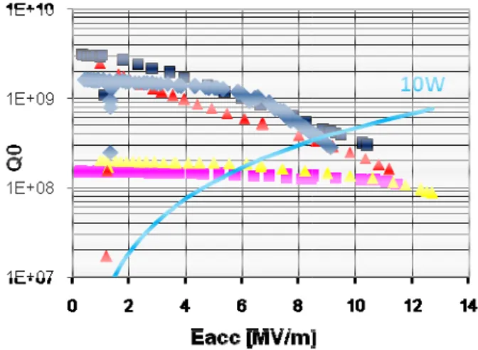
Early tests of the AZ-1 cavity sho (10 times lower than expected) [3]. Th Q0 was caused by the dual purpose se
linking the cavity to its bottom cap demonstrated by replacing these seal (see Fig. 1) during vertical cryostat these copper seals are replaced by Hel
Figure 1: Vertical tests results of the th Two bottom curves (yellow and pink copper, dual purpose seal. All other cavities with an indium seal. The blu cavity with an indium seal and copper Tests in the qualification cryomodu very difficult to maintain the niobium 10K, mainly due to the thermal loss coupler. Therefore niobium caps hav high RRR copper caps. Compu additional RF losses would be 1 W in of RRR=70 copper. The AZ-1 cavity
NAC
nce
power tests of the pective labs.
E A
as first been tested 2009 [3]. Recently, on cavity (AZ-1) has ssembled inside its have begun in April
s cavities (AZ-2 and each manufacturer.
wed a very poor Q0
he degradation of the eal (RF and vacuum) p. This failure was ls with indium ones tests. From now on licoflex© seals.
hree A-type cavities. k) are cavities with a curves are the three ue dot curve show a r bottom cap. ule proved that it was
m bottom cap below ses coming from the ve been replaced by utations show that
n a bottom cap made has been tested with
D
MOPD025 Proceedings of IPAC’10, Kyoto, Japan
732
04 Hadron Accelerators A08 Linear Accelerators
such a copper cap in vertical cryostat; results proved satisfactory (see Fig. 1).
Fine tuning of the cavities is performed chemically. Removing thickness preferentially at the top of the cavity (magnetic torus) lowers the frequency, whereas removing niobium preferentially at the bottom of the cavity (around the beam tubes) raises the frequency.
A new magnetic shield has been developed and manufactured. It is made of 1-mm thick Mumetall© plates
assembled on the inside wall of the vacuum chamber. Its efficiency has been measured and is better than 50 around the cavity.
Ongoing Activities
The qualification cryomodule is presently being tested in Saclay. Cavity inside this cryomodule is the AZ-1 one, with a copper bottom cap fitted with a Helicoflex© seal.
Preliminary results showed that alignment of the cavity inside the cryostat is unsatisfactory and shall be enhanced. We still have the possible adjustment of moving the whole cryomodule on axis at the price of a reduction of the apparent beam aperture. The cryogenic system shall also be slightly modified to limit apparent cryogenic losses and to stabilize the helium bath level; the real cryomodule consumption has still to be measured.
Coupler conditioning was performed easily both at 300 K and at 4 K. Conditioning procedure includes both pulsed and cw modes; pulsed modes are operated at 50Hz. Usual multipacting barriers have been observed at low power level (around 20 and 150 W of peak input power).
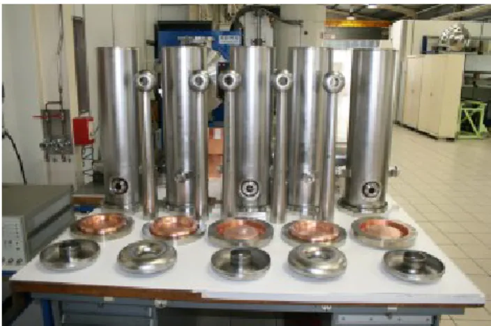
Figure 2: Series cavities just before tuning operation in the manufacturer premises.
A prototype LLRF system foreseen for the accelerator has been successfully tested. Despite high helium consumption (and with helium bath pressure fluctuations of ±2 mbar), the LLRF and tuning systems managed to maintain the phase shift within ±0.1° with respect to the RF pilot (specifications: ±0.5°), and the field amplitude in the cavity within ±0.12% (specifications: 1%).
The tuning system performed satisfactorily, until it blocked after 12,000 motor turns. The harmonic drive gear box, operating under vacuum and at 4 K, and the CuBe screw are under suspicion.
Further tests are being performed and full analysis of the results still has to be made.Series cavities fabrication is ongoing smoothly and according to schedule (see Fig. 2). All cavities are presently in the tuning stage. Tuning is performed by adjusting the cavity height: last two welds are the ones linking the stem to the top torus and the top torus to the cavity body respectively (as seen on Fig. 2). By cutting the stem and the cavity body to the proper length, it is possible to adjust the resonance frequency of the cavity with a sensitivity of 83 kHz/mm. This system has been qualified by both manufacturers on AZ-2 and AS-3 cavities. Manufacturers are required to deliver all cavities with a frequency precision of ±25 kHz.
Foreseen ctivities and chedule
All elements of the first series cryomodule have been delivered in Saclay. This cryomodule shall be assembled during the summer 2010 with the AZ-2 cavity. This cavity has already been tuned but shall be finally qualified in vertical cryostat before being put in the cryomodule. Tests of this cryomodule are scheduled for September 2010.
All series cavities shall be delivered in Saclay between June and September 2010. Upon reception they will be tuned chemically and individually tested in vertical cryostat for final acceptance. It is scheduled that all cavities will be qualified before the end of 2010. It will be the first final cryomodule.
In parallel, remaining cryomodules components, presently under fabrication, will be delivered before the end of the year in two or three batches. Assembly of the 10 remaining cryomodules shall begin before the end of 2010.
Final delivery of the last tested cryomodule to GANIL is foreseen for the first quarter of 2011.
CRYOMODULE B
Cavities ests
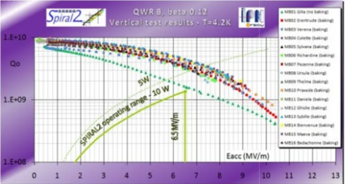
The production of the 16 beta 0.12 cavities was achieved in November 2009 (see Fig. 3). All cavities have already been tested once in vertical cryostat at 4.5 K (see Fig. 4). There all satisfy the SPIRAL2 linac requirements (less than 10 W of dissipated power at 6.5 MV/m).
Figure 3: Family picture of some B cavities.
A
S
T
Proceedings of IPAC’10, Kyoto, Japan MOPD025
04 Hadron Accelerators
Figure 4: Vertical tests results for all 16 typ All cavities have been BCP etched. In o more homogenous etching rate, the chemica done in two phases (2x2h, the cavity is t down after the first phase) and the cavit down” by circulating water within its h during the process. We ended up with a +0.14 kHz/min, with a very good r (±0.02 kHz/min) for more than 15 chemical The dissipated power at 6.5 MV/m has be a factor of two (mean value of 4 W inst thanks to the baking of each cavity at 110°C baking is done in clean room after HPR directly blown in the stem and goes out b CF16 flanges of the helium vessel (see Fig ensures baking of the bottom end of the ca not in contact with the helium vessel. T wrapped in a foil blanket during the process.
Figure 5: Sketch of the hot air flux for cav
Figure 6: MB14 cavity equipped with magnetic shield. pe B cavities. order to get a al treatment is turned upside ty is “cooled helium vessel sensitivity of reproducibility processes. een divided by tead of 8 W), C for 48 h. The R. Hot air is by one of the g. 5). A heater avity, which is The cavity is . vity baking. its dual-layer
Magn
The two first magnetic shields hav April 2010. The magnetic shield is layers of 1-mm thick Cryoperm© a
cooling circuit. The goal is to cool-d 20 K) the magnetic shield before the transition, to ensure that the shie optimal at the time of the transition. successfully tested with the MB14 cryostat (see Fig. 6). The temperatur around 30 K before the cavity transitio
Cryomodules Fabrication
In addition to the prototype cryom installed in the linac tunnel than performances [4], the production cryomodules B components is going 2010. Three cryomodules have alread IPN Orsay; the last one will be deliver The assembly of the first cryomod cryomodule should be tested in Sep cryomodule will be individually teste every 2 months, before shipment to G
RF POWER COUP
21 of the 30 power couplers have b LPSC laboratory in Grenoble.
The ceramic window of two first c during conditioning, seemingly becau too thick. A thinner on (1nm) was tes gave higher multipacting. Therefore abandoned for the remaining couplers
Of the remaining 19 delivered cou fully tested and conditioned. No inc couplers are being delivered to the cry teams in Saclay and Orsay according t Following the cryomodule A and B 2010, the method to keep the temper window above 14°C (to avoid freezi Two options are still being consid regulated heater will be placed on the close as possible to the ceramic, or flown in a channel around the ceramic
REFERENCES
[1] T. Junquera, P. Bertrand, R Jacquemet, “The high intensi Linac for the SPIRAL 2 proje LINAC 2006, Knoxville, USA, p [2] Y. Gómez Martínez et al., “T experimental result of the RF co Spiral2”, EPAC 06, Edinburgh, Ju [3] P.-E. Bernaudin et al., “Tests stat
low beta cryomodules”, PAC’0 2009, TU5PFP041.
[4] G. Olry et al., “SPIRAL2 cryom first results”, SRF09, Berlin, Sept
ve been delivered in s posed of two and a stainless steel down (ideally below
normal to SC cavity elding efficiency is
One shield has been 4 cavity in vertical
re of the shield was on.
module which will be nks to very good n of the 6 other to be ended in June dy been delivered to red in October 2010. dule has begun. This
ptember 2010. Each ed at IPN Orsay, one GANIL.
PLERS
been received by the couplers broke down use TiN coating was sted with success by e TiN coating was s.
uplers, 6 have been cident occurred and yomodules assembly to schedule.
B tests next autumn rature of the ceramic ing) will be chosen. dered: either a self
e outer conductor as r filtered air will be c.
S
R. Ferdinand, M. ity superconducting ct at GANIL”, Proc. 142-144.heorical study and oupler prototypes of une 2006.
tus of the SPIRAL 2 9, Vancouver, May modules: status and tember 2009.
etic Shield
com
MOPD025 Proceedings of IPAC’10, Kyoto, Japan
734
04 Hadron Accelerators A08 Linear Accelerators


