HAL Id: cea-02509712
https://hal-cea.archives-ouvertes.fr/cea-02509712
Submitted on 17 Mar 2020
HAL is a multi-disciplinary open access
archive for the deposit and dissemination of
sci-entific research documents, whether they are
pub-lished or not. The documents may come from
teaching and research institutions in France or
abroad, or from public or private research centers.
L’archive ouverte pluridisciplinaire HAL, est
destinée au dépôt et à la diffusion de documents
scientifiques de niveau recherche, publiés ou non,
émanant des établissements d’enseignement et de
recherche français ou étrangers, des laboratoires
publics ou privés.
Analysis of selective laser melting of resorbable
bioceramics
P. Aubry, O. Hercher, D. Nimal, D. Marchat
To cite this version:
P. Aubry, O. Hercher, D. Nimal, D. Marchat. Analysis of selective laser melting of resorbable
bioce-ramics. ICALEO 2015 - The 34th International Congress on Applications of Lasers & Electro-Optics,
Oct 2015, Atlanta, United States. paper 1905. �cea-02509712�
ANALYSIS OF SELECTIVE LASER MELTING OF RESORBABLE BIOCERAMICS
Paper #1905
Pascal Aubry1, Olivier Hercher1, Didier Nimal2, David Marchat3
1 CEA/DEN/DANS/DPC/SEARS/LISL, CEA Saclay, 91191 Gif-sur-Yvette Cedex, France 2 Osseomatrix, 9100 Evry, France
3 Ecole Nationale Supérieure des Mines de Saint-Etienne, Centre Ingénierie et Santé, UMR CNRS 6638, Saint-Etienne, France
Abstract/Manuscript
Since few years, an intense research activity has been undertaken on obtaining orthopedic implants by direct laser manufacturing. Metallic (titanium alloys) heap implants have been the first parts obtained by laser cladding, with dental implants (chromium cobalt alloys) obtained by selective laser melting. In parallel, different studies have been initiated on direct manufacturing of bioceramics. These materials have the main advantage to be completely or partly replaced by real bone after colonization by bone cells. From that family, Hydroxyapatite (HAP) and Tri Calcium Phosphate (TCP) material are the best candidates because their compositions are close the real bone.
This article presents the experiments we have conducted to generate TCP structure by selective laser melting. These are part of a French research project ORTHOFLASE related to this topic. First, powder provision and quality has been identity as a critical point for the success of the project. Ultrapure TCP with very low metallic pollutant content has been manufactured.
As the TCP powder produced is very pure, it has been necessary to control its absorptivity for existing laser sources. Very low absorptivity of the powder has been evidenced at continuous laser at near infrared wavelength (YAG, fiber or near infrared diode lasers). However, the powder has exhibited a very good absorptivity for far infrared CO2 laser.
Then, a parameter study has been undertaken on an existing selective laser melting device with CO2
laser. The main parameters are the powder layer thickness, the laser power, and the travel speed. The process parameter window is determined and results of the experiments are presented.
Finally, from considerations of the material structure required for a good colonization by the bone cells, simple 3D geometries are manufactured presented in the article.
Introduction
Diseases of the musculoskeletal system are the leading cause of disability and cost to public health in the U.S. It has been widely reported in the United States an awareness campaign musculoskeletal problems that was designed to advance research for the prevention, diagnosis and treatment of these conditions with an associated costs representing 849 billion dollars per year for the years from 2002 to 2004. Demography (baby boomers) impacts the cost of care for these conditions and this trend through demographic change and the aging population will only be confirmed in the next ten years. Fifteen million adults (7% of the population) in the U.S. report having difficulty performing their daily activities related to a disorder of the musculoskeletal system (50% among 45-64 years). The problems are related to trauma, back pain, followed by arthritis and osteoporosis problems.
Among these conditions some can cause significant loss of bone tissue. The most common are: • trauma: falls are the leading cause followed by traffic accidents and sporting activities. The costs in the USA is estimated at U.S. $ 127.4 billion. Among the million fractures each year in France 5-10% for long periods with no bone repair, representing 700,000 patients in the United States and 600,000 in Europe and some cases can lead to amputation treatment.
• cancers: primitive bone cancer, the most common are osteosarcoma and Ewing's sarcoma but can also be in the form of fibrosarcoma or histiocytoma.
Bone cancers occur in younger than other types of cancer (50% are under 40 years and 28% within 20 years) patients. Metastatic cancers mainly affect over 50 years. 75% of patients who survive their cancer require surgery. Benign or malignant bone tumors are the cause of significant loss of bone volume.
• bone loss at Musculoskeletal can also be of prosthetic origin. A typical example is the recovery of total hip arthroplasty with bone loss of the acetabulum. The number of hip prostheses in place is around 120,000 per year in France. The life of a prosthesis is 10 to 15 years. The recovery rate is 13% or about 18,000 cases / year (source statistics PMSI).
To repair the bone loss of critical mass harvesting bone from the iliac crest of the patient has become the first option. Apart from the fact that the available bone volume is limited, it requires additional surgery increases morbidity.
At the present time, in order to reduce the cost of management of these diseases and improve the quality of life of patients, we are driven to seek less invasive methods reducing morbidity and surgical risk. Thus use is made increasingly to synthetic materials such as bioceramics which have the advantage of being unlimited volume. Of these bioceramics of calcium phosphate and calcium carbonate having a composition similar to the mineral part of bone have given the best results. When they are porous these bioceramics have osteo-conduction properties but do not exhibit osteogenic or osteoinductive character.
Furthermore commercial bioceramics are in simple geometric shapes which must then be reworked. This is why an approach bone bioengineering intended to meet the needs of critical size bone loss, this project proposes to provide customized bio hybrid programmed bone porosity tricalcium phosphate (β TCP) and custom made for guiding bone growth and serve as a support for inducing
proteins or mesenchymal cells.
The expected result is better management of critical size bone loss with medical and socio-economic impact:
• shorter duration of operation with reduced post-operative care and hospital stay • improving the quality of life of the patient: less postoperative pain and faster recovery.
Conventional methods used for the shaping of the ceramic (or molding or machining projection) does not allow the creation of implants of complex
internal architecture that only the direct fabrication (in English also called "additive manufacturing" or "free form "manufacturing", "layer manufacturing" or "rapid prototyping") makes possible. Such rapid prototyping processes, the laser melting of powder bed is adapted to controllably produce parts with a complex internal architecture compared to other methods such as :
• Optform method (stereolithography pasty phase) or the 3D printing, which require a binder resin for bonding the grains of material and an intermediate delicate debinding operation-sintering to remove the binder and obtain a ceramic piece good (with risk deformation and removal of 15-20%); • projection of material in laser beam (cladding) more oriented towards the production of bulky objects.
The process of fusion laser powder bed (commonly names SLM, Selective Laser Melting) also has industrial, environmental and economic. If the method of laser melting of powder bed tends to develop in medical applications with biocompatible materials such as metals (titanium and alloys, cobalt-chrome ..) or polymers (PMMA, PEEK, Caprolactone ..), it has not been used directly with hydroxyapatite bioceramics kind (PAHs) or tricalcium phosphate (β TCP) because it requires a specific development. This is why it was decided to experiment in the context of this innovative project direct laser melting on a bed of powder β-tricalcium phosphate (TCP Ca3 (PO4) 2) for the production of bioceramic implants for compensate for significant bone loss.
A highly innovative approach has been formalized by international patents in 2009 and 2010 by the company Osseomatrix SAS, with ENISE (National Engineering School of St Etienne) establishing a proof of concept for the manufacture of 'Hydroxyapatite implants (nonabsorbable). For orthopedic applications it was decided to experiment with β-tricalcium phosphate resorbable TCP because of its relationship with the mineral phase of natural bone and the need for long term only mature bone, only able to withstand mechanical loads in orthopedics. The implant is designed as an osteoconductive macroporous architecture and allows the accommodation of mesenchymal stem cells taken from the patient and amplified in a subsequent bioreactor cell culture processes. During the consolidation phase, the strength of the home resection will be temporarily provided by the addition of an osteosynthesis material.
Following this initial studies, a French ANR (National Research Agency) project “OrthoFlase” has started. The goal of the project is to implement a beat TCP prosthesis manufacturing chain in SLM process, under the supervision of Osseomatrix, the project leader. The powder is manufactured by Ecole Nationale Supérieure de Mines de Saint-Etienne. CEA (CEA/DEN/DPC/SEARS/LISL) will be in charge of SLM process. The results will be evaluated biologically by the B2OA (laboratory biomaterial articular bone biology) on animal models. Sisn’Com company will provide an internet based software environment to the surgeon that will be able to manipulate 3D data and CAD model of the implant to adapt it the the defect. tof the defect to the computer-aided design implant (CAD) in which the surgeon operates remotely on key parameteers via interoperability platform before the manufacture of the workpiece by direct laser melting.
Calcium Phosphates
Calcium phosphate preparation
Bone is a highly specialized extracellular matrix and closely associated with a solid mineral. This part consists of mineral hydroxyapatite crystals polysubstituted. One suggested by the literature on bone calcified tissue formulas is as follows Ca8, 3
(PO4)4,7(HPO4, CO3)1,3(OH, CO3)0,3 [1].
The calcium phosphate ceramics (CAPS) are commonly used clinically as bone substitutes. Among these materials, the chemical formula of hydroxyapatite Ca10(PO4)6(OH)2 (HA) and
tricalcium phosphate β Ca3(PO4)2 (β TCP), are
frequently used as a biomaterial and have been many studies. Their clinical interest results in terms of their similarity in chemical composition with the mineral phase of bone tissue, their perfect biocompatibility with human tissue and their bioactivity [2, 3, 4, 5, 6].
The chemical properties and biological behavior (especially biodegradation) of calcium phosphate bioceramics, dependent on their physicochemical characteristics and more particularly to their composition (molar ratio Calcium / Phosphorus). The solubility of calcium orthophosphates increases when the Ca/P molar ratio of the compound decreases [1,7]. The β TCP (Ca/P = 1.50) and is two times more soluble than HA (Ca/P = 1.67) in water [8] and twelve times more acid [9] environment. Biologically, β TCP is fully resorbable while hydroxyapatite degrades only superficially [2, 10].
Precipitation methods in aqueous phase are conventionally used to prepare powders of calcium phosphates [11, 12]. For a molar ratio C/ P of 1.50 ideal, the precipitate is obtainable CA9 apatitic tricalcium phosphate (HPO4)(PO4)5(OH), nH2O
(apatite TCP). The anhydrous crystalline tricalcium phosphate Ca3(PO4) 2(TCP) was obtained after
calcination at 750-800°C of this apatite compound by condensation of hydrogenophosphate ions, according to the overall reaction [13] :
Ca9(HPO4) (PO4) 5OH, nH2O 3 Ca3(PO4) 2 + (n
+1)H2O Eq. 1
Between 1150 ° C and 1200 ° C the β phase of rhombohedral-type tricalcium phosphate (β TCP) is transformed into the monoclinic phase (α TCP). This allotropic transformation causes a relative increase in cell volume of 7% [14, 15]. A second allotropic transformation occurs at 1450 ° C. The synthesis of CaPs is most often done by precipitation from calcium and phosphate pH and temperature controlled and regulated [16]. The general chemical precipitation reaction in aqueous medium CaPs can be written:
6(NH4)2HPO4 + (10-x)Ca (NO3)2 + (8-2x)NH4OH
Ca10-x(PO4)6-x (HPO4)x(OH)2-x + (20-2x) NH4NO3
Eq. 2
The apatite is the only TCP orthophosphate precipitated a molar ratio equal to 1.50. A small deviation of the molar ratio Ca/P around this ideal composition causes the formation of a mixture of apatite and TCP monetite (DCPA, CaHPO4) for Ca /
P <1.500, or a deficient HA calcium Ca 10-x (HPO4) x
(PO4) 6-x (OH) 2-x (0 <x <1) relative to a 1,500 <Ca /
P <1.667. The precipitated phases decompose during heat treatment [12, 1, 14]. Calcium deficient HA Ca10-x(HPO4)x (PO4) 6-x (OH) 2-x (0 <x <1) and
the apatite TCP (x = 1) decompose above 750 ° C according to the reaction overall following [12]: Ca10-x (HPO4) x (PO4) 6-x (OH) 2-x (x-1) Ca10 (PO4) 6 (OH) 2 + 3x Ca3 (PO4) 2 + xH2O Eq. 3
For a Ca / P <1.500, the monetite (DCPA) becomes pyrophosphate (CPP) [14]
2CaHPO4 Ca2P2O7 + H2O (450 ° C)
Ca2P2O7 (850 ° C) Eq. 4
A small change settings synthesis (molar ratio of reactants, temperature and pH synthetic atmosphere, ripening time ...) and can generate significant variations in the composition of the synthesized powders. For example, a relative change of 1% of
the Ca / P ratio results in the formation of 10% by weight of HA to an excess of calcium, and about 2.5% by weight of CPC in the contrary case. However, the variation of the composition of the organic powders and heat changes their behavior [12, 14, 15, 17].
Powder preparation and Analysis
The powder has been provided by Ecole Nationale Supérieure des Mines de Saint-Etienne. The powder is made by the following sequences of operations : 1. Synthesis of TCP
2. Filtration and Grinding
3. Cycles of Calcination and grinding 4. Slurry preparation and Spray drying 5. Debinding and Sintering
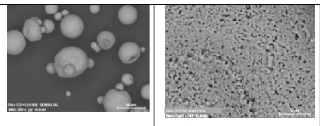
This process is required in order to generate a powder adapted to the SLM process, that is, spherical powder in the granulometry range between 20 to 50µm. The figure hereunder show the powder produced for the experiments.
Figure 3: EBM views of the produced powder The powder is globally spherical with some satellite with a diameter <100µm. That seems to be out of range for conventional SLM process (i.e for metallic materials). However, is respect to the requirements of the parts to be produced, this size distribution can be acceptable. This will be adapted in the next batch production.
The powder (see Figure 3) exhibits a fine microstructure with some occluded or open porosities which is not critical for the application
Selective Laser Melting Process
The principle of the method of laser melting of powder bed is the following: a powder layer of defined thickness is homogeneously deposited on a substrate. A CAD file of the 3D part is decomposed into distinct horizontal plane by a CAD software. Each plan is a section of the room. For each layer, the laser beam scans the surface of the powder and
merges in areas that constitute the part. It is thus built layer by layer. This method is therefore particularly suitable for the manufacture of parts with complex geometry and having a small size may be internal structure (typically less than 250x250x250mm). This process is the only time to perform complex geometries perfectly controlled (design, macroporosity, Interconnects ...) and direct way and without removal unlike other methods of formatting such as by foaming agents by replica (organic foams, naphthalene balls or PMMA) or rapid prototyping (3D printing, stereolithography ...).
In the case of 3D powder printing is "stuck" with a polymer [18]. According to the method, a nozzle can release the adhesive and scan the surface of the powder bed or a powder-depositing binder in order to build the geometry. A vintage "green" product and thus must be thermally treated to remove the polymer (debonding). Unfortunately, the 3D geometry can be difficult to control and the mechanical properties of the material remain low. The material obtained by the 3D printing process has high porosity filled by the polymer. Full density material requires a post process of debinding at hot isostatic pressure that causes a significant shrinkage of the part as well as deformations that are difficult to predict. The SLM process has the advantage to be a one stage process. The full density part is directly obtained after the process With the accuracy of the laser, the macrostructure of the material (pore size, morphology and distribution) can be perfectly controlled. It is also possible to adjust the microscopic properties of the material during manufacture of the layer at the workpiece.
Figure 1: Principle of a SLM machine
Figure 2: Direct manufacturing process, the CAD file to the room.
- -
The process of laser melting of powder bed has been implemented and studied since the early 2000s for the direct manufacture of metal parts. The aim was to produce parts of complex geometry with a state of good enough surface to perform their function. Early work focused on the production of molds for plastics processing tool steel (Z38CDV5) and stainless steel (316L) [19]. Subsequently, several studies have concerned the direct manufacture of metal components for the aerospace (parts TA6V Inconel718, aluminum alloys) [20] [21]. At the same time, studies have been conducted on parts manufacturing CoCr, mainly dedicated to the direct
manufacture of dentures.
On ceramics, studies have mainly carried on making parts of alumina, mullite or zirconia for the direct manufacture of ceramic casting core. Note that, in this case, the material obtained remains porous
(porosity greater than 15%).
Apart from some work done on zirconia [22] and those related to laser projection [23] [24], which comes close, very few studies have been conducted on the direct fabrication by laser sintering of ceramics [25] [26] which gives the 3D topography of the defect to the computer aided design of the implant (CAD) in which the surgeon operates remotely on key parameters via interoperability platform before fabrication of the part by melting direct laser.
Experimental Setup
The experimental study has been undertaken on a dedicated SLM demonstrator. The machine is presented in Figure 3. It consists of a provision material and a process chamber. The layering system is a rotating cylinder with a groove that can be used as layering device. The system can be closed for a gas protective atmosphere.
Figure 3: SLM demonstrator used for the process parameter search
SLM parameter study
Selection of the laser type
If the SLM systems for metallic components can be generally equipped with NIR type wavelength
(typically around Nd:YAG sources 1,064µm), the laser wavelength must be considered with this material. The material absorption depends of the main elements of the composition of the material (here TCP) but of the minor elements that cannot be eliminated in certain powder manufacturing processes. For example, previous works has evidenced that NIR laser (typically fiber lasers) can be used for the fusion of industrial HAP powder. This seems to be mainly due to the presence of metallic impurities like Co, Fe, …
Nowadays, there are several type of lasers offering a large range of wavelengths at high brightness quality, typically with fiber lasers. Considering the material, two range of wavelengths can be tested :
from visible to near infrared wavelengths that can be provided by fiber lasers as, for example NIR fiber laser (~1,07µm)
medium to far infrared wavelength as, for example CO2 lasers.
Both types of lasers available at the laboratory have been tested in a series of preliminary experiments on melting of powder spread over the TCP 200 microns thick.
The tests showed that the TCP powder provided for the project twas transparent to the wavelength of the Nd: YAG and fiber lasers. At the opposite, it proves to be very absorbent at the wavelength of the CO2
laser. This is mainly due to the very high purity of the TCP. This was not the case with over industrial Consequently, it has been decided to start the study with a CO2 laser. The other possibility is to try to increase the absorbtivity of the Nd:YAG or fiber laser wavelength by adding some elements that leads to a good one. This has been investigated in a second stage.
Parameter study with a CO2 laser
The parametric study consisted of achieving fusion lines on beds of powder of chosen thickness disposed on the glass plates. Some surface scanning has been tested later on.
A first series of tests was carried out at maximum power. The principle was to study the influence of the moving speed of the laser beam through the scanner. The ranges of parameters are studied here:
Constant Power: 50 W (laser focused - Df = 0 mm
Speed: 1- 60 m/mn
Powder thickness was 200 and 400 microns. At high speed, it is seen that the powder is melted in places (drops) but is insufficient to create fusion cords and adhere to the substrate. After cleaning, the glass is completely blank. This confirms that the material is absorbent to the wavelength of the CO2 laser. Below a speed of 3 m / min, continuous seams are created in the powder bed is lowered and more speed, the more they expand. However, they create a trench in the bed of powder which extends beyond the width of the same seam, which could be disadvantageous when overlapping between seams. On Figure 4, the effect of speed on the fusion line can be observed. The glass allows to see not only the seam viewed from above, but also by transparency, seen from below. This provides information on the integrity thereof. All seams are extra thick and therefore are formed from the
merger of the TCP powder.
Scanning speed must be below 2 m/min for a continuous. However, the seams seem cracked internally. The seams constructed to have a width of 300 to 500 microns.
V=6m/mn V=3m/mn V=2m/mn
V = 2 m/min V = 1,5 m/min V = 1 m/min
Figure 4 : Observation of fused TCP tracks for different speeds
The same type of images was performed on tracks built in a powder bed 400 m thick. Logically, an equivalent condition, the seams are constructed, but with more difficulty, as a powder bed height of 200 microns. In particular, it is necessary to go down to 1 m / min in order to melt the powder continuously. Trials on steel plate coated
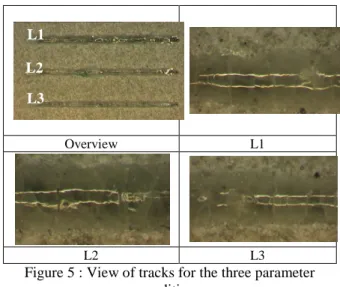
It was not possible to use radiant heating on the TCP coated steel substrate, so we just made some tests at room temperature. The best beads obtained "cold" were for speeds between 1 and 2 m / min with a power of 52 W (maximum power). 3 conditions
have been tested : P=52W, V=1m/mn (L1), 1.5m/mn (L2), 2m/mn (L3), no heating, beam diameter 200µm.
The results are encouraging because the seams are continuous and well adherent to the substrate in the powder bed. However, they are cracked. This can be seen in Figure 5 once the powder is cleaned. Their width is between 200 and 300 microns.
Overview L1
L2 L3
Figure 5 : View of tracks for the three parameter conditions
A test was performed in the cover (5 square mm x 5 mm). But the molten material has not held. The poor adhesion from the fact that the original tracks are melted, eliminate cracks by adapting the parameters. This could be done by heating the device. It was not possible within the framework of this study.
If this demonstrates the possibility to build a 3D structure by fusing the powde with CO2 laser, some issued remain. First the CO2 laser leads to a laser absoptivity on the top of the powder layer that could lead to difficulty to generate a good 3D structure. Secondly, CO2 laser is less flexible for integration than fiber laser. Because of that and from an industrial point of view, fiber laser system would be better and, therefore, this type of laser has been tested for the SLM of our TCP Ppowder.
Parameter study with a fiber laser Selection of composition of the powder
As it has been said, the pure TCP does not interact significantly with the laser at fiber laser wavelength. If this type of laser wants to be used, wich is particularly important for an industrial point of view, the powder has to be modified by addition of absorbing element. Obtaining the final powder can be made in different way such as mixing to types of
L2 L1
powder (TCP + additive powder) or premixing of additive element to TCP before final atomization. In this article and as the first approach, it has bee decided to mix to different powders. Concerning the additive elements, some elements exhibiting a very good absorbtivity at fiber laser wavelength such as TiC, SiC, Iron Oxyde,… By considering the biocompatibity of these elements, SiC particules have been selected first. Different SiC particules have been tested, from micron to nano size.
Influence of process parameters on the fused structure
As stated in the CO2 laser analysis, all the trails have been made on HAP coated stainless steel plates (up to 500µm HAP thickness).
The process parameter has been undertaken the same way as previously. The main process prarmeters have been scanned on small samples: Laser power, Scanning speed, Layer thickness, Laser spot Size at surface, Scanning strategies,… Figure 6 presents some plate showing different samples in parameters and scanning strategies. It can be seen that some parameter set has led to 3D structures while others have failed. The search starts with a large scan of the process parameter window (mainly laser power 10-100W and scanning speed 10mm/mn-600mm/mn). Thus, bad samples are eliminated and a new plate is made again with selected parameters. The scanning strategies and the 3D geometry analysis is introduced later on. Two main scanning strategies are investigated:
One direction scanning : the powder bed is scanned by parallel tacks at a fixed distance
Crossed scanning: the powder bed is scanned at two successive orthogonal directions with fixed distance between two tracks.
1 2
Figure 6 : Two plates of process parameter study. 1) intial parameter study, 2) first optimization step
Material Analysis
Figure 7 : verrtical cross section of a 3D sample (parallel scanning)
The test samples have been analysis by macrography, micrography and XRD.
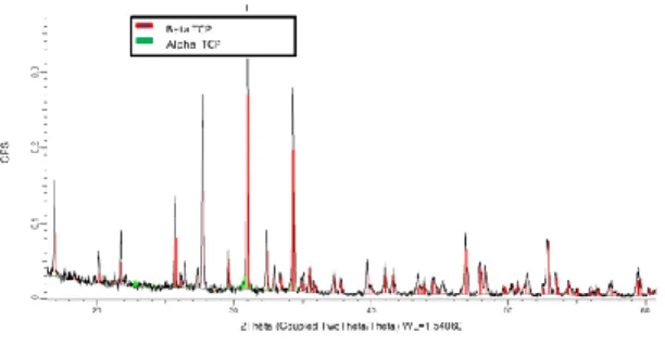
The macrography analysis exhibits the glonal structure of the material. Tracks are formed by the fusion of the powder. If the small walls can be seen (the samples are been all made by repetition of the same pattern), a lot of porosities and cracks are visible (see Figure 7). This is mainly due to vaporization of some part of the material and the high thermal gradient due to the process parameters. However, if the cracks weaken the structure, the resistance of the material to the pressure and manipulation is fully enough to be used. Moreover, a post heat treatment could reduce these defects. XRD analysis has been made on different samples and process parameters. However, the results appear very similar. The spectra show a lot of peaks that are not easy to separate, even after a XRD analysis of the beta TCP powder. Globally, as it can be seen in Figure 8 and following different references as for example [27] , beta-TCP is easily identified. Alpha-TCP can be present too, even if low quantity. Hydroxy apatite (HAP) has not been identified.
Figure 8 : XRD analysis of 3D sample
Manufacturing of 3D samples
3D structure have been manufactured with the most promising parameter set that provide a good geometry and a material resistance to manipulation and compression as much as possible (in relation to
lower defects and better fusion of the powder). Small samples have been manufactured as, for example, cylindrical shape sample visible in Figure 8.
Selection of optimized parameters has allowed manufacturing 3D structure as showed in Figure 9. The cube is dilled by one horizontal and one vertical hole that demonstrate the capability to build different holes in the sample for a better vascularization.
1a 1b
2a 2b
Figure 8: Top view of two cylindrical samples( at: global view, a: detail, 1 : line of fusion in one
direction only, 2: crossed fusion lines)
Figure 9 : 3D object made with fiber laser on TCCP+absorbing element
Biocompatibilty and osteointegration analysis
The biocompatibility evaluation is a very important part of the project. If elementary material produced must demonstrated a good growth cell on in vitro
tests, the 3D structure of the implants is crucial for a good cell colonization in the material, a good circulation of fluids, and a good vascularization, that is the way the vessels organize in the implant. The samples presented in this article are dedicated to in vitro tests. However, in vitro tests have been made in parallel with 3D samples manufactured by indirect a rapid prototyping technique (3D printing with the same TCP powder followed by a post heat treatment.
Figure 10 shows a 3D sample made of TCP and micro-structured in a way that can be reproduced by SLM (compare with SLM manufactured 3D structure on Figure ). The results are very promising, showing a very good cell growth in the volume of the sample. Osteointegration is clearly visible in the figure and demonstrates an adequate structure and material. Further experiments will be made with SLM made samples.
1 2
3
Figure 10 : 1) 3D implant, 2) positioning sample on topof mouse head, 3) Osteointegration of in vivo sample (about 10mmx10mm) after implantation on
mouse (green/black : TCP implant, red : bone tissue)
Conclusion
This study shows that TCP sample can be manufactured by SLM. In C02, the study has demonstrated the capability of fusing the bioceramics for generation the 3D structure. Concerning the SLM process at fiber laser wavelength, the very pure beta-TCP powder produced during the OrthoFlase project has a very low absorptivity at this wavelength range and, therefore, a addition of laser absorbing component as SiC, TiC,… is required. The article demonstrated
that this approach can lead to a good fusion of the material.
The first analysis of the manufactured material showed that the TCP is globally conserved, even if the phase is partly but little changed from beta to alpha. This can be optimized by a post heat treatment after the SLM process.
In parallel, in vivo and in vitro test on small animals has demonstrated the very biocompatibility of the TCP material. Different 3D structures have been tested and some samples exhibited very good vascularization thanks toot the strcuturation of the material with adapted 3D structure (channels and pore size) that can be organized in a deterministing way with SLM
The next step of the study will be to continue biological tests, make process parameter and, powder manufacturing optimization. Final in vivo test by testing real implants on big animals (typically tarsus sheep) would conclude the study before industrialization.
References
[1] J.C. Elliot (1994). Structure and chemistry
of the apatites and other calcium orthophosphates.
Studies in inorganic chemistry, Amsterdam, Elsevier Science B.V.
[2] M. Jarcho. “Calcium phosphate ceramics
as hard tissue prosthetics”. Clinical Orthopaedics
and Related Research., 157, 259-278, 1981.
[3] K. De-Groot (1983). “Ceramics of calcium
phosphate: preparation and properties”.
Bioceramics of calcium phosphate. K. D. Groot. Boca Raton, Fl, USA, CRC Press: 99-114.
[4] N. Passuti et G. Daculsi (1989). "Céramiques en phosphate de calcium en chirurgie
orthopédique". La Presse Médicale, 18: 28-31.
[5] L.L. Hench (1991). "Bioceramics: from
concept to clinic". J. Am. Ceram. Soc., 74:
1487-1510.
[6] C. Véron, M. Chanavaz, J. Ferri, M. Donazzan et H.F. Hildebrand (1995). "Biomatériaux
et biocompatibilité". Rev. Stomatol. Chir.
maxollifac., XXXIVème Congrès: 274-281.
[7] D. Bernache-Assollant (1993). "Les
biocéramiques : élaborations et propriétés".
L'Industrie Céramique & Verrière. 883: 421-436.
[8] M. Yashima, A. Sakai, T. Kamiyama et A. Hoshikawa (2003). "Crystal structure of
β-tricalcium phosphate Ca3(PO4)2 by neutron powder
diffraction". J. Solid State Chem., 175: 272-277.
[9] M. Kohri, K. Miki, D.E. Waite, H. Nakajima et T. Okabe (1993). "In vitro stability of
biphasic calcium phosphate ceramics".
Biomaterials, 14: 299-304.
[10] P.S. Eggli, W. Muller, R. K. Schenk (1988). Porous hydroxyapatite and tricalcium
phosphates cylinders with 2 different pore-size ranges implanted in the cancellous bone of rabbits – A comparative histomorphometric and histologic study of bony ingrowth and implant substituion.
Clinical Orthopaedics and Related Research. 127-138
[11] H. Chaair, J.-C. Heughebaert, M. Heughebaert and M. Vaillant (1994). “Statistical Analysis of Apatitic Tricalcium Phosphate preparation”. Journal of Materials Chemistry. 4(5): 765-770.
[12] S. Raynaud, E. Champion, D. Bernache-Assollant, P. Thomas (2002). “Calcium phosphate
apatites with Ca/P atomic ratio I. Synthesis, characterization and thermal stability of powders”.
Biomaterials; 23; 1065-1072.
[13] A. Mortier, J. Lemaître et P.G. Rouxhet (1989). "Temperature-programmed characterization
of synthetic calcium-deficient phsophate apatites".
Thermochim. Acta, 143: 265-282.
[14] A. Destainville, E. Champion, D. Bernache-Assollant, E. Laborde (2003). “Synthesis,
Characterization and thermal behavior of apatitic tricalcium phosphate”. Materials Chemistry and
Physics. 80 : 269-277.
[15] M. Descamps, J. C. Hornez, A. Leriche; Journal of the European Cearmic Society (2007). “Effects of powder stoichiometry on the sintering of
-tricalcium phosphate”. 27; 2401-2406.
[16] S. Raynaud. Thèse de doctorat : Synthèse,
frittage et propriétés mécaniques de phosphates de calcium dans le système hydroxyapatite-posphate tricalcique. 181.
[17] D. Bernache-Assollant, A. Ababou, E. Champion, M. H. Eughebaert (2003). “Sintering of
calcium phosphate hydroxyapatite
growth”. Journal of the European Ceramic Society.
23: 229-241
[18] S. Michna, W. Wu, J. Lewis (2005) "Concentrated hydroxyapatite inks for direct-write
assembly of 3-D periodic scaffold". Biomaterials, 26
(2005); 5632-5639
[19] N. Coulon, Y. Lafaye, P. Aubry, “Analysis
of the Laser Sintering Process for Direct Manufacturing of Mould”, Proc. ICALEO2006,
paper 1803, Phoenix, USA, 2006
[20] P. Aubry, P. Robert, O. Hercher, “Analysis of the Powder Bed Laser Melting Process For Direct Manufacturing of Metallic Components”, Proc. PICALO 2008, Beijing, China, 2008
[21] P. Aubry, K. Verdier, T. Malot, O. Hercher, J. Maisonneuve, C. Colin, “Direct
Manufacturing of Components by Laser Metal deposition an Powder Bed Laser Melting” Proc. of
LAMP2009, Kobe, Japan, June 2009
[22] Ph. Bertrand, F. Bayle, C. Combe, P. Goeuriot, I. Smurov (2007). “Ceramic components
manufacturing by selective laser sintering”. Applied
Surface Science; 254; 989-992.
[23] D. Wang, C. Chen, J. Ma, G. Zhang (2008). "In situ synthesis of hydrixyapatite coating
by lase cladding” colloids and surfacesB:
Biomaterials, 66 (2008): 155-162 J. Solid State Chem., 175: 272-277.
[24] R. Comesaña, F. Lusquiños, J. del Val, T. Malot, A. Riveiro, F. Quintero, M. Boutinguiza, P.Aubry, J. Pou “Laser-Assisted Processing of 3D
Bioceramic Structures”, Proc. ICALEO 2009, pp
1055-1061
[25] Webb, P.A. (2000) “A review of rapid
prototyping (RP) techniques in the medical and biomedical sector”. J. Med. Eng. Technol. 24,
149-153.
[26] Griffin, A., McMillin, S., Griffin, C., Barton, K. (1997) “Bioceramic RP materials for
medical models”. Proceedings of the 7th
International Conference on Rapid Prototyping, University of Dayton and Stanford University, 355-359.
[27] Borodajenko N., Salma K., Berzina-Cimdima, “Characterization of calium phosphate synthesis products by XRD”, poste seesion, 11th European Powder Diffraction Conference, 2008
Acknowledgment
The study related in the article is a part of the Orthoflase Project. The authors thank the Agence Nationale de la Recherche for funding the project and Conseil Général des Yvelines for the funding of the SLM demonstrator.
The authors thank Pr. Hervé Petite and Dr. Didier Hannouche from LB2OA Université Paris 13, OrthoFlase partner, for their contribution to the biological tests.
Meet the Author(s)
Dr Pascal J. Aubry is Senior Expert in Laser Processing at Atomic Energy Commission (CEA) and manager of Surface Treatment and Additive Manufacturing Platform (STAMP) at Arts et Métiers ParisTech. His research activities are mainly related to additive manufacturing, surface treatment and process control.
Email: pascal.aubry@cea.fr,
pascal.aubry@ensam.eu
Dr. Didier Nimal is the OrthoFlase project coordinator has completed a twenty years in the industrial sector in the medical market and managed subsidiaries of the leading groups in the market for implants experience. It is also involved for ten years in the training cycle university degree facial prosthesis taught at the Faculty of Medicine at the Pitié-Salpêtrière. He founded the company OSSEOMATRIX SAS to develop production and marketing of bioceramic implants with innovative architectures and capabilities for custom reconstruction and bone regeneration applications. Dr. David Marchat is Researcher at Ecole des Mines de Saint-Etienne, Centre Ingénierie et Santé, UMR CNRS 6638. After his PhD in physico-chemistry, he has been research engineer at Medtronic Sofamor Danek Company, Deggendorf, Germany where he continued his research on synthesis of bioceramics. Finally, he moved at Ecole de Mines. His research interest are related to biomaterials, synthesis of biomaterials, materials for bone substitutes, Tricalcium Phosphates, synthesis of nano powder and related processes.