Coexistence of Pinning and Moving on a Contact Line
The MIT Faculty has made this article openly available. Please share how this access benefits you. Your story matters.Citation Lu, Zhengmao et al. “Coexistence of Pinning and Moving on a Contact Line.” Langmuir 33, 36 (August 2017): 8970–8975 © 2017 American Chemical Society
As Published http://pubs.acs.org/doi/abs/10.1021/acs.langmuir.7b02070
Publisher American Chemical Society (ACS)
Version Author's final manuscript
Citable link http://hdl.handle.net/1721.1/117384
Terms of Use Article is made available in accordance with the publisher's policy and may be subject to US copyright law. Please refer to the publisher's site for terms of use.
1
Coexistence of Pinning and Moving on a Contact Line
Zhengmao Lua, Daniel J. Prestona, Dion S. Antao, Yangying Zhu, and Evelyn N. Wangb
Department of Mechanical Engineering, Massachusetts Institute of Technology, Cambridge, Massachusetts 02139, USA
a Zhengmao Lu and Daniel J. Preston contributed equally to this work b To whom correspondence should be addressed: enwang@mit.edu
2
Abstract
Textured surfaces are instrumental in water repellency or fluid wicking applications, where the pinning and depinning of the liquid-gas interface plays an important role. Previous work showed that a contact line can exhibit non-uniform behavior due to heterogeneities in surface chemistry or roughness. Here, we demonstrate that such non-uniformities can be achieved even without varying the local energy barrier. Around a cylindrical pillar, an interface can reside in an intermediate state where segments of the contact line are pinned to the pillar top while the rest of the contact line moves along the sidewall. This partially pinned mode is due to the global non-axisymmetric pattern of the surface features and exists for all textured surfaces, especially when superhydrophobic surfaces are about to be flooded or when capillary wicks are close to dryout.
3
Introduction
Rough, structured surfaces are used to manipulate the liquid-gas interface primarily for two purposes: fluid repellency1-3 for self-cleaning4-5, water harvesting6, anti-icing7, antifouling8, and enhancing condensation9-12; and capillary wicking for thermal management13-16, microfluidics17-19, and fluid separation20. In both cases, liquid and gas are separated by a capillary surface21 which
self-regulates its shape in response to the interfacial pressure difference. Prior work has recognized the importance of the capillary surface evolution and the contact line pinning/depinning in these applications, where the contact line has been commonly considered to be either fully pinned or mobile22-32.
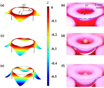
In this work, we show through experiments and modeling a hybrid wetting state during which contact line pinning and motion coexist. Similar coexistence behavior has been reported in literature for a sessile drop placed on a substrate with heterogeneities in surface chemistry or roughness33-37. In these cases, the local energy barrier, which governs the pinning/depinning or contact angle hysteresis in general, is manipulated by along the contact line. However, we demonstrate that the contact line can exhibit uniform behavior simply due to the global non-axisymmetric pattern of the surface features, without variation in the local energy barrier. Since this non-axisymmetry is present for all textured surfaces, the current work is relevant for all of the fluid repellency and wicking applications described above. In this study, with a regular pillar array system38-44, as we varied the interfacial pressure difference, we observed the fully pinned mode of the contact line in Fig. 1 (a) and (b) and the fully mobile mode in Fig. 1 (e) and (f); additionally, between these two modes, we show the existence of the previously unexplored partially pinned mode in the absence of local energy barrier variation in Fig. 1 (c) and (d).
4
Fig. 1 Model solution and experimental observation of the capillary surface around a cylindrical pillar in a square array: (a) and (b) Regime (I) fully pinned mode; (c) and (d) Regime (II) partially pinned mode; (e) and (f) fully mobile mode. The colors in (a), (c), and (e) represents the z coordinates of the capillary surface. The blue dash lines in (b), (d) and (f) indicate the contact line position. The major difference between the model ((a), (c), and (e)) and the experiment ((b), (d) and (f)) is the Bo. The former assumes Bo ≪ 1 while the latter corresponds to Bo = 6.3. Nevertheless, the same three regime behavior was observed in both the model and the experiment. Noting that gravity only tends to flatten the interface, the experimental observations qualitatively support the modeling results.
Model Formulation
To understand the interface behavior during the transition from a pinned to mobile contact line, we established a model framework based on first principles, where we examined the capillary surface in a unit cell of a square-patterned cylindrical pillar array, representative of structures on engineered surfaces. We denote the pillar radius as r, center-to-center spacing as L, and gap between pillars as s = L – 2r, and establish a Cartesian coordinate system at the center of one of
5
the pillars (Fig. 2 (a) and (b)). The shape of the interface is described by z = f (x, y). Due to symmetry, we restrict the problem domain to one eighth of the unit cell and consequently apply symmetry boundary conditions on boundaries 1, 2 and 3 in Fig. 2 (c). By the pressure balance across the interface,
0 2
P gz
(1)
where ΔP0 is the interfacial pressure difference from phase 2 to phase 1 in Fig. 2 (a) evaluated at
the highest point of the interface (z = 0), σ is the surface tension, κ is the interface mean curvature, Δρ is the density difference from phase 1 to phase 2, and g is the gravitational constant. Normalizing the both sides of Eq. (1) to the characteristic capillary pressure σ/r, we have
0 Bo 2 P z r r r
(2)where Bo = Δρgr2/σ is the Bond number21 of the system. From this dimensionless equation, it is clear that the system’s behavior is dominated by Bo and the ratio between the interface geometry and pillar radius. Note that when Bo ≫ 1, gravity dominates, resulting in a flat interface as the right hand side of Eq. (2) becomes negligible, so any non-uniform behavior of the contact line should be caused by capillarity. When Bo ≪ 1, κ remains constant in a unit cell as the gravitational term diminishes, reducing Eq. (2) to the Young-Laplace equation. Applying concepts from differential geometry45, κ, which is positive when phase 2 curves into phase 1, can be determined from the outward-pointing unit normal vector of the interface n̂ = ∇f /||∇f || (Fig. 2 (a)):
ˆ 2 . n
(3)
6 1,2,3,4 ˆ ˆ ˆb nds n n dl
(4)The left hand side is the gradient of n̂ integrated over the problem domain in Fig. 2 (c) and the right hand side is the dot product between n̂ and n̂b integrated over boundaries 1, 2, 3, and 4 in Fig.
2 (c), where n̂b is the boundary unit normal vector pointing outwards. Due to the symmetry, n̂ ∙ n̂b
= 0 on boundaries 1, 2, and 3. On boundary 4, n̂b = n̂4 = (-x, -y, 0). Combining Eq. (3) and Eq. (4),
we have: 4 4 ˆ ˆ 2 ds n n dl
(5)Eq. (3) is a second-order partial differential equation that governs the shape of the capillary surface z = f (x, y). With proper boundary conditions specified at boundary 1, 2, 3 and 4, it can be solved by the finite element method where we applied the sparse object-oriented linear equations solver46 and used free triangular meshing with 40508 domain elements and 2124 boundary elements while the relative tolerance for convergence was set to be 10-6 (see Supplemental Material Section I for a comparison between the present work and the Surface Evolver47 approach).
Modeling Results and Discussion
We set r = 1 to normalize the pillar array dimensions to its radius and L = 2.5 as a reference geometry. When the contact line is fully pinned at the top of the pillar, we have a Dirichlet condition (z = 0) on boundary 4, which enables us to solve Eq. (2) and Eq. (3) for a given κ. For example, setting κ = 0.6, we plot the shape of the capillary surface around one pillar in Fig. 1 (a). We evaluate the apparent contact angle θ as the angle between n̂ and n̂4 with cos θ = n̂ ∙ n̂4. When
7
the contact line is fully mobile along the sidewall, the boundary condition on the contact line is determined by θ = θr, where θr is the receding contact angle of phase 1 (or the advancing contact
angle of phase 2) and the capillary surface generates the maximum mean curvature κ = κr. The
divergence theorem in Eq. (5) then reduced to
2 2
2 cos . 8 4 r r L r r (6)For example, setting θr = 30°, we obtain that κr ≈ 0.875 and plot the capillary surface in Fig. 1 (e).
Between the Regime (I) fully pinned mode and the Regime (III) fully mobile mode, there exists a partially pinned mode (Regime (II)) where part of the contact line depins and the rest remains pinned. For instance, with L = 2.5, κ = 0.8 and θr = 30°, we plot the z = f (x, y) solution in Fig. 1
(c) for the partially pinned regime. Generally, to determine whether the capillary surface falls into the partially pinned regime given a κ < κr, first z = f (x, y) is solved assuming the fully pinned mode
and θ is plotted against the polar angle α=arctan(y/x) along the contact line. The capillary surface stays in the fully pinned mode if and only if θ ≥ θr at every location of the contact line. In Fig. 2
(d), when θr = 30° and κ = 0.6, θ ≥ θr for any α (Regime (I)). However, when κ = 0.8, we observe
that θ < θr for part of the contact line, which indicates that the contact line partially depins and
transitions into the partially pinned mode (Regime (II)). Then, we need to relax the boundary condition on the contact line to be either z = 0 or θ = θr while enforcing the continuity in z and θ.
In Fig. 2 (e), the contact line location is plotted against α (0° ≤ α ≤ 45°) for all three modes (κ = 0.6 fully pinned, κ = 0.8 partially pinned, and κ = κr fully mobile regimes), which elaborates on
the contact line behaviors as κ or equivalently ΔP0 increases. The evolution of the capillary surface
is important for determining the flooding criteria on superhydrophobic surfaces and the thermal-fluidic resistance in thermal management and microthermal-fluidic devices based on capillary wicks (see
8
Supplemental Material Section II). We note that the model that we developed here does not necessarily capture the dynamics of the contact line. For example, the depinning event at one point can instantly change the curvature of the capillary surface in its surrounding48. Therefore, the evolution of the interface is depicted by this model only in a quasi-static way.
Fig. 2 (a) Schematic side view of capillary surface formed in pillar arrays. (b) Top view of a unit cell of a square pattern cylindrical pillar array. (c) Problem domain for solving the capillary surface: only 1/8 of the interface in the unit cell is simulated due to symmetry. (d) Contact angle θ plotted against polar angle α for L = 2.5, κ = 0.6 (blue solid line) and κ = 0.8 (red dotted line) in the fully pinned mode. (e) Contact line location as a function of polar angle α for κ=0.6, κ=0.8 and κ = κr when θr = 30°.
In all three regimes, there is non-uniformity in either θ or z on the contact line. For example, in the fully pinned mode in Fig. 2 (d), θ is smaller where α is larger. As ΔP0 increases, the interface
becomes more curved to generate a larger capillary pressure and θ decreases down to the limit of θr. Consequently, where α is larger, θ will approach θr first. As ΔP0 is increased further, the
depinning of contact line starts from the location where α = 45°, moving in the direction of decreasing α. As a result, when the contact line fully depins, it is at a lower location for larger α, as indicated in Fig. 2 (e). We attribute this non-uniformity to the non-axisymmetry of the square
9
pattern of the pillar array even though the cylindrical pillar itself is axisymmetric. Due to this mismatch, not every location on the contact line transitions from pinned to mobile at the same time, which is the reason that the partially pinned regime exists. In general, Regime (II) exists for any surface which is not axisymmetric.
Experimental Results and Discussion
To verify the findings of our model, we created two square patterned cylindrical pillar arrays using nylon pillars, 12.7 mm in diameter with gap between pillars s = 1.5 mm and 2.3 mm, respectively. We used a solution of Rhodamine B in water (2.09 mM) as the working fluid. The surface tension was determined to be 62 mN/m using the pendant drop method49, which agrees with literature
data50. At this length scale, the gravitational term in Eq. (2) becomes comparable to the capillary term as Bo = 6.3. The quasi-static receding contact angle of the solution on the pillar surface is measured to be θr = 10° with the dynamic sessile drop method. During the experiment, we slowly
pulled out the liquid from the pillar array (with a Capillary number for the receding fluid of Ca ≈ 7 × 10⁻⁷) and observed that pinning and depinning occurred on the pillar surface as shown in Fig.
1 (b), (d), and (f). Noting that gravity only tends to flatten the interface, these observations qualitatively support our modeling results for the Bo ≪ 1 case. To quantitatively validate our model, we solved Eq. (2) with Bo = 6.3 and compared its prediction to the contact line location obtained from the fully mobile mode (Fig. 1 (f)) via image processing (see Supplemental Material Section III). Fig. 3 (a) shows good agreement between the model and experiment, where the only model inputs are Bo, θr and the pillar array geometries. In fact, we also observed the same contact
10
scanning electron microscope with water as the working fluid44 (see Supplemental Material Section IV). We also note that the pillar surface in practice is not perfectly smooth and can induce local pinning. However, this only influences the contact line behavior at the length scale of the surface roughness and the non-uniform receding that we observed at the length scale of the pillar radius is caused by the non-axisymmetry of the surface structure pattern.
Fig. 3 (a) Model validation using the contact line location in the fully mobile mode for two sample pillar arrays (Bo = 6.3): the light blue curve and dark blue diamond symbols represent the model prediction and experimental data, respectively, for a square array of 12.7 mm diameter pillars with 2.3 mm gap between pillars; the light red curve and red triangle symbols represent the model prediction and experimental data, respectively, for a square array of 12.7 mm diameter pillars with 1.5 mm gap between pillars. (b) Variation in the contact line location (δCL) as a function of L for square pattern and hexagonal pattern pillar arrays for
Bo ≪ 1 (c) Top view of a unit cell of a hexagonal pattern pillar array. (d) Problem domain with boundary conditions for predicting the capillary surface in a hexagonal pattern pillar array.
Fig. 3 (a) shows that the z coordinates of the contact line vary around the pillar in Regime (III). This is because the contact line does not depin simultaneously in Regime (II), which again originates from the non-axisymmetry of the surface structure pattern. We evaluated δCL, the
11
this non-axisymmetric effect. In Fig. 3 (b), δCL is plotted as a function of L for square pattern pillar
arrays (blue solid line). Note that the interaction between neighboring cells is through the non-axisymmetric periodic boundaries disturbing the capillary surface around the pillar. As L increases and the distance between the pillar and the periodic boundary is larger, this interaction becomes weaker and δCL diminishes. In the extreme case where L → ∞, it corresponds to the constant mean
curvature problem around a single cylindrical pillar, which is by nature axisymmetric and results in δCL = 0. If we replace the square pattern with a hexagonal pattern, δCL as a function of L (red
dotted line in Fig. 3 (b)) follows a similar trend. However, at the same L, δCL is smaller for the
hexagonal pattern than the square pattern, as one pillar has more nearest neighbors in the hexagonal pattern. Note that in the hexagonal pattern pillar arrays, the capillary surface is still governed by Eq. (2). The unit cell is given in Fig. 3 (c) and the problem domain can be reduced to one twelfth of the unit cell due to symmetry (Fig. 3 (d)). This δCL is of significance when coatings are applied
to surface structures to further tune surface wettability51-52. To achieve the desired effect, the coating must be of good quality down to the depth δCL to which the contact line extends.
Conclusion
This work investigated the capillary surface evolution as a function of the interfacial pressure difference and demonstrated an intermediate regime of the liquid-vapor interface where only part of the contact line is mobile while the rest is still pinned. This intermediate regime fundamentally originates from the non-axisymmetry of the surface structure pattern and gives rise to the extension of the contact line length when the contact line becomes fully mobile. This partially pinned mode can play an important role when the structured surface is close to dry-out in fluid wicking, or when
12
the trapped air layer is about to be flooded during fluid repellency. As the surface structures are packed closer, which generally enhances capillarity, we observe a more pronounced partially pinned mode. We anticipate that surface structures can be finely designed to tune this partially pinned mode, which is potentially useful for water-repellency, microfluidics, and phase change heat transfer applications.
Acknowledgement
We gratefully acknowledge funding support from the Air Force Office of Scientific Research with Dr. Ali Sayir as program manager and the Office of Naval Research (ONR) with Dr. Mark Spector as program manager. D.J.P. acknowledges funding received by the National Science Foundation Graduate Research Fellowship under Grant No. 1122374. Any opinion, findings, conclusions, or recommendations expressed in this material are those of the authors(s) and do not necessarily reflect the views of the National Science Foundation. This work was performed in part at the Center for Nanoscale Systems (CNS), a member of the National Nanotechnology Infrastructure Network (NNIN), which is supported by the National Science Foundation under NSF award no. ECS-0335765. CNS is part of Harvard University.
13
References
1. Quéré, D.; Reyssat, M. Non-adhesive lotus and other hydrophobic materials. Philosophical Transactions of the Royal Society of London A: Mathematical, Physical and Engineering Sciences
2008, 366 (1870), 1539-1556.
2. Yao, X.; Chen, Q.; Xu, L.; Li, Q.; Song, Y.; Gao, X.; Quéré, D.; Jiang, L. Bioinspired ribbed nanoneedles with robust superhydrophobicity. Adv. Funct. Mater. 2010, 20 (4), 656-662. 3. Liu, T. Y.; Kim, C. J. Turning a surface superrepellent even to completely wetting liquids. Science 2014, 346 (6213), 1096-1100.
4. Nishimoto, S.; Bhushan, B. Bioinspired self-cleaning surfaces with superhydrophobicity, superoleophobicity, and superhydrophilicity. Rsc Advances 2013, 3 (3), 671-690.
5. Duez, C.; Ybert, C.; Clanet, C.; Bocquet, L. Making a splash with water repellency. Nat. Phys. 2007, 3 (3), 180-183.
6. Brown, P. S.; Bhushan, B. Bioinspired materials for water supply and management: water collection, water purification and separation of water from oil. Phil. Trans. R. Soc. A 2016, 374 (2073), 20160135.
7. Boreyko, J. B.; Collier, P. C. Delayed Frost Growth on Jumping-Drop Superhydrophobic Surfaces. Acs Nano 2013.
8. Genzer, J.; Efimenko, K. Recent developments in superhydrophobic surfaces and their relevance to marine fouling: a review. Biofouling 2006, 22 (5), 339-360.
9. Preston, D. J.; Miljkovic, N.; Enright, R.; Wang, E. N. Jumping Droplet Electrostatic Charging and Effect on Vapor Drag. Journal of Heat Transfer 2014.
10. Boreyko, J. B.; Chen, C. H. Self-Propelled Dropwise Condensate on Superhydrophobic Surfaces. Phys Rev Lett 2009, 103 (18), 184501-1 - 184501-4.
11. Narhe, R.; Beysens, D. Nucleation and growth on a superhydrophobic grooved surface. Phys. Rev. Lett. 2004, 93 (7), 076103.
12. Cavalli, A.; Preston, D. J.; Tio, E.; Martin, D. W.; Miljkovic, N.; Wang, E. N.; Blanchette, F.; Bush, J. W. M. Electrically induced drop detachment and ejection. Phys Fluids 2016, 28 (2). 13. Cho, H. J.; Preston, D. J.; Zhu, Y.; Wang, E. N. Nanoengineering materials for liquid– vapour phase-change heat transfer. Nature Materials Reviews 2016, 2 (16092).
14. Zhu, Y.; Antao, D. S.; Lu, Z.; Somasundaram, S.; Zhang, T.; Wang, E. N. Prediction and Characterization of Dry-out Heat Flux in Micropillar Wick Structures. Langmuir 2016, 32 (7), 1920-1927.
15. Lu, Z.; Narayanan, S.; Wang, E. N. Modeling of evaporation from nanopores with nonequilibrium and nonlocal effects. Langmuir 2015, 31 (36), 9817-9824.
16. Lu, Z.; Salamon, T. R.; Narayanan, S.; Bagnall, K. R.; Hanks, D. F.; Antao, D. S.; Barabadi, B.; Sircar, J.; Simon, M. E.; Wang, E. N. Design and Modeling of Membrane-Based Evaporative Cooling Devices for Thermal Management of High Heat Fluxes. IEEE Transactions on Components, Packaging and Manufacturing Technology 2016, 6 (7), 1056-1065.
17. Jung, S. M.; Preston, D. J.; Jung, H. Y.; Deng, Z. T.; Wang, E. N.; Kong, J. Porous Cu Nanowire Aerosponges from One-Step Assembly and their Applications in Heat Dissipation. Adv Mater 2016, 28 (7), 1413-1419.
18. Martinez, A. W.; Phillips, S. T.; Whitesides, G. M. Three-dimensional microfluidic devices fabricated in layered paper and tape. Proceedings of the National Academy of Sciences 2008, 105 (50), 19606-19611.
14
19. Copic, D.; Park, S. J.; Tawfick, S.; De Volder, M. F.; Hart, A. J. Fabrication of high-aspect-ratio polymer microstructures and hierarchical textures using carbon nanotube composite master molds. Lab Chip 2011, 11 (10), 1831-1837.
20. Mates, J. E.; Schutzius, T. M.; Qin, J.; Waldroup, D. E.; Megaridis, C. M. The Fluid Diode: Tunable Unidirectional Flow through Porous Substrates. ACS Applied Materials & Interfaces 2014, 6 (15), 12837-12843.
21. De Gennes, P.-G.; Brochard-Wyart, F.; Quéré, D. Capillarity and wetting phenomena: drops, bubbles, pearls, waves; Springer Science & Business Media2013.
22. Lobaton, E.; Salamon, T. Computation of constant mean curvature surfaces: Application to the gas–liquid interface of a pressurized fluid on a superhydrophobic surface. J. Colloid Interface Sci. 2007, 314 (1), 184-198.
23. Nam, Y.; Sharratt, S.; Byon, C.; Kim, S. J.; Ju, Y. S. Fabrication and characterization of the capillary performance of superhydrophilic Cu micropost arrays. Microelectromechanical Systems, Journal of 2010, 19 (3), 581-588.
24. Mognetti, B. M.; Yeomans, J. Modeling receding contact lines on superhydrophobic surfaces. Langmuir 2010, 26 (23), 18162-18168.
25. Byon, C.; Kim, S. J. Study on the capillary performance of micro-post wicks with non-homogeneous configurations. Int. J. Heat Mass Transfer 2014, 68, 415-421.
26. Ranjan, R.; Patel, A.; Garimella, S. V.; Murthy, J. Y. Wicking and thermal characteristics of micropillared structures for use in passive heat spreaders. Int. J. Heat Mass Transfer 2012, 55 (4), 586-596.
27. Semprebon, C.; Forsberg, P.; Priest, C.; Brinkmann, M. Pinning and wicking in regular pillar arrays. Soft Matter 2014, 10 (31), 5739-5748.
28. Ranjan, R.; Murthy, J. Y.; Garimella, S. V. Analysis of the wicking and thin-film evaporation characteristics of microstructures. J. Heat Transfer 2009, 131 (10), 101001.
29. Moulinet, S.; Bartolo, D. Life and death of a fakir droplet: Impalement transitions on superhydrophobic surfaces. The European Physical Journal E 2007, 24 (3), 251-260.
30. Kusumaatmaja, H.; Blow, M.; Dupuis, A.; Yeomans, J. The collapse transition on superhydrophobic surfaces. EPL (Europhysics Letters) 2008, 81 (3), 36003.
31. Whyman, G.; Bormashenko, E. How to make the Cassie wetting state stable? Langmuir
2011, 27 (13), 8171-8176.
32. Ball, P. How wet can you get? Nat. Phys. 2016, 12 (7), 718-718.
33. Shanahan, M. E. Capillary movement of nearly axisymmetric sessile drops. J. Phys. D: Appl. Phys. 1990, 23 (3), 321.
34. Shanahan, M. A simple analysis of local wetting hysteresis on a Wilhelmy plate. Surf. Interface Anal. 1991, 17 (7), 489-495.
35. Shanahan, M.; Di Meglio, J. Wetting hysteresis: effects due to shadowing. J. Adhes. Sci. Technol. 1994, 8 (11), 1371-1380.
36. Woodward, J.; Gwin, H.; Schwartz, D. Contact angles on surfaces with mesoscopic chemical heterogeneity. Langmuir 2000, 16 (6), 2957-2961.
37. Joanny, J.; De Gennes, P.-G. A model for contact angle hysteresis. The Journal of Chemical Physics 1984, 81 (1), 552-562.
38. Yeo, J.; Choi, M. J.; Kim, D. S. Robust hydrophobic surfaces with various micropillar arrays. J. Micromech. Microeng. 2010, 20 (2), 025028.
39. Kim, S. J.; Moon, M.-W.; Lee, K.-R.; Lee, D.-Y.; Chang, Y. S.; Kim, H.-y. Liquid spreading on superhydrophilic micropillar arrays. J. Fluid Mech. 2011, 680, 477-487.
15
40. Li, J.; Hou, Y.; Liu, Y.; Hao, C.; Li, M.; Chaudhury, M. K.; Yao, S.; Wang, Z. Directional transport of high-temperature Janus droplets mediated by structural topography. Nat. Phys. 2016. 41. Liu, Y.; Moevius, L.; Xu, X.; Qian, T.; Yeomans, J. M.; Wang, Z. Pancake bouncing on superhydrophobic surfaces. Nat. Phys. 2014, 10 (7), 515-519.
42. Dhillon, N. S.; Buongiorno, J.; Varanasi, K. K. Critical heat flux maxima during boiling crisis on textured surfaces. Nature communications 2015, 6.
43. Raj, R.; Adera, S.; Enright, R.; Wang, E. N. High-resolution liquid patterns via three-dimensional droplet shape control. Nature communications 2014, 5.
44. Paxson, A. T.; Varanasi, K. K. Self-similarity of contact line depinning from textured surfaces. Nature communications 2013, 4, 1492.
45. Do Carmo, M. P. Differential geometry of curves and surfaces; Prentice-hall Englewood Cliffs1976; Vol. 2.
46. Ashcraft, C.; Grimes, R. G. In SPOOLES: An Object-Oriented Sparse Matrix Library, PPSC, 1999.
47. Brakke, K. A. Surface evolver manual. Mathematics Department, Susquehanna Univerisity, Selinsgrove, PA 1994, 17870 (2.24).
48. Papadopoulos, P.; Mammen, L.; Deng, X.; Vollmer, D.; Butt, H.-J. How superhydrophobicity breaks down. Proceedings of the National Academy of Sciences 2013, 110 (9), 3254-3258.
49. Hansen, F.; Rødsrud, G. Surface tension by pendant drop: I. A fast standard instrument using computer image analysis. J. Colloid Interface Sci. 1991, 141 (1), 1-9.
50. Hatano, Y.; Katsumura, Y.; Mozumder, A. Charged Particle and Photon Interactions with Matter: Recent Advances, Applications, and Interfaces; CRC Press2010.
51. Preston, D. J.; Mafra, D. L.; Miljkovic, N.; Kong, J.; Wang, E. N. Scalable Graphene Coatings for Enhanced Condensation Heat Transfer. Nano Lett 2015, 15 (5), 2902-2909.
52. Preston, D. J.; Miljkovic, N.; Sack, J.; Enright, R.; Queeney, J.; Wang, E. N. Effect of hydrocarbon adsorption on the wettability of rare earth oxide ceramics. Appl Phys Lett 2014, 105 (11601).
16
1
Supplementary Information
Coexistence of Pinning and Moving on a Contact Line
Zhengmao Lua, Daniel J. Prestona, Dion S. Antao, Yangying Zhu, and Evelyn N. Wangb Department of Mechanical Engineering, Massachusetts Institute of Technology, Cambridge,
Massachusetts 02139, USA
I. Comparison Between Our Method and Surface Evolver
We compare results from our current method and the more commonly used Surface Evolver (SE) approach in Fig. S1, using a unit cell from a square pattern array with cylindrical pillars as a benchmark case with r = 1, L = 2.5, θr = 30° and Bo ≪ 1. With our method, given a mean curvature κ, we solve for the capillary surface and calculate the liquid volume V in one unit cell. On the other hand, in SE, we choose a V, evolve the interface into a constant mean curvature surface and evaluate κ as the Lagrange multiplier. Fig. S1 gives V as a function of κ evaluated from both methods, showing excellent agreement.
Indeed, SE can handle a larger breadth of problems. Nevertheless, it is generally difficult to determine how close the surface is to the minimum energy configuration (the true solution) in SE, whereas it is easier to test the convergence and specify the relative error based on a certain mesh density using our current approach which relies on the finite element method to solve partial differential equations. Furthermore, to apply the capillary surface shape as the geometric constraint to the wicking or non-wetting applications, the interface shape has to be given as a function of pressure or κ. Following the previous approaches using SE with the volume constraint, one has to first solve for the dependence of the interface shape on the choice of V and then correlate V to κ,
a Zhengmao Lu and Daniel J. Preston contributed equally to this work b To whom correspondence should be addressed: enwang@mit.edu
2
which relates the shape to κ in an indirect manner. Meanwhile, the current approach directly gives the capillary surface shape as a function of κ, which facilitates integrating this method as a subroutine into modeling and optimization of geometric parameters for functioning of structured surfaces.
Fig. S1 Volume V as a function of curvature κ evaluated using both our current method (solid blue line) and SE (solid red squares), which are in excellent agreement.
II. Implications of Capillary Surface Evolution
As κ varies, there are also changes in the lowest location on the interface (zmin) and the interface
surface area normalized over its projection area (A*) (Fig. S2). When κ is small, the capillary surface is relatively flat, which makes A* close to 1 and zmin close to 0. As κ increases, the interface
extends into the unit cell, which causes the actual interface area to increase, i.e., A* > 1, and the capillary surface to come closer to the bottom substrate (zmin decreases). In fluid repellency
3
the wicking process, a smaller zmin means larger flow resistance for liquid transport and A*
corresponds to the area for possible interfacial heat/mass transfer15. Hence, this work has important
implications for superhydrophobic surfaces and fluidic-based thermal management applications which have not been well-captured in past work.
Fig. S2 Lowest location on the interface zmin (blue solid line) and its normalized surface area A*
(orange dotted line) as a function of κ.
III. Image Processing for the Fully Mobile Contact Line
To verify the findings of our model, we created square patterned pillar arrays using nylon pillars with the water solution of Rhodamine B as the working fluid. Using a digital camera, we captured the fully mobile mode in Fig. S3. To determine the exact contact line location, we first extracted the pillar edge coordinates (Curve 1 in Fig. S3) in pixels and fit it with an ellipse. Since this ellipse is also the projection of the circular pillar cross-section, this gives us the camera tilting angle αc = arcos (b/a), where a and b are the semi-major and semi-minor axes of the ellipse, respectively.
4
The ellipse fitting also provides the x-coordinate of the center of the contact line x0. We then export
the contact line coordinates (Curve 2 in Fig. S3) in pixels. To compare Curve 2 to our model, the relative position in the x-direction has to be converted to that along the pillar circumference. The relative position in the y-direction is determined by the difference between Curve 1 and Curve 2, adjusted by αc. Since the major axis of the ellipse is parallel to the camera projection plane, a also
represents the undistorted pillar radius to which we normalize all of the dimensions.
Fig. S3 Image processing on the fully receding mode to extract the contact line location.
IV. Contact Line Receding in Silicon Micropillar Arrays
We experimentally observed all three regimes (Regime (I) fully pinned regime, Regime (II) partially pinned regime and Regime (III) fully mobile regime) on microfabricated silicon pillar arrays (Fig. S4 (a)) with an environmental scanning electron microscope (ESEM, EVO 50, Carl Zeiss). Imaging was performed with a 500 μm lower aperture to allow extended water vapor pressure inside the chamber, and the backscatter detector was used to collect the image. The ESEM chamber was first purged with water vapor over five cycles to remove noncondensable gases. The pillars were then cooled to 2 °C on a Peltier stage inside the ESEM and water vapor was condensed
5
on the pillars at 110% relative humidity until the sidewalls were completely wetted, corresponding to Regime (I) and shown in Fig. S4 (b). The relative humidity was adjusted to 98% to promote evaporation of the water in order to observe the receding contact line behavior. Initially, the interface remained in Regime (I), but as evaporation continued and the volume of water present on the samples decreased, Regimes (II) and (III) were observed as the contact line receded down the pillar sidewall, shown in the time lapse in Fig. S4 (c), where the location of the CL started to vary on the pillar surface.
Fig. S4 (a) Cylindrical silicon pillars were microfabricated for experimental imaging of the receding contact line with an environmental scanning electron microscope (ESEM). (b) The pillars were cooled and water vapor was condensed onto the pillars until their walls were completely wetted, corresponding to Regime (I). (c) This time lapse, zoomed into the sidewall of one pillar, shows the subsequent receding of the contact line during evaporation of liquid water; Regime (II) is present from 0 to 2.5 sec, after which Regime (III) is observed.
a)
b)
c) 0 sec 0.5 sec 1.0 sec
1.5 sec 2.0 sec 2.5 sec
3.0 sec 3.5 sec 4.0 sec
6
V. Capillary Surface in Square Cross-Section Micropillar Arrays
The current method can be easily extended to any micropillar array of cross-section. For example, Fig. S5 (a) shows a unit cell of a square pattern micropillar array with pillars of square cross-section. The problem domain is constrained by symmetric boundaries and the CL. We plot the capillary surface in the fully receding regime for the case where the pillar side length as = 1 and L
= 2.5 in terms of the 2-D contour solution in Fig. S5 (b) and reconstruct the 3-D geometry in Fig. S5 (c). In Fig. S5 (c), the CL on square shape micropillars is not as smooth as the one on cylindrical micropillars due to the presence of a sharp corner which corresponds to a singularity in curvature. In reality, the micropillar corner can only contain a finite curvature, which would make the CL smoother.
Fig. S5 (a) Top view of a unit cell of a square pattern micropillar array with pillars of square cross-section. (b) 2-D contour map of the interface shape in the problem domain. (c) 3-D reconstruction of capillary surface around one pillar in a square pattern micropillar array with pillars of square cross-section.