HAL Id: hal-01222122
https://hal.archives-ouvertes.fr/hal-01222122
Submitted on 29 Oct 2015
HAL is a multi-disciplinary open access archive for the deposit and dissemination of sci-entific research documents, whether they are pub-lished or not. The documents may come from teaching and research institutions in France or abroad, or from public or private research centers.
L’archive ouverte pluridisciplinaire HAL, est destinée au dépôt et à la diffusion de documents scientifiques de niveau recherche, publiés ou non, émanant des établissements d’enseignement et de recherche français ou étrangers, des laboratoires publics ou privés.
Using the Design of Experiments (DoE) Method to
Elaborate an Electrical Ageing Model for the Insulation
of Low Voltage Rotating Machines Fed by Inverters
Nadine Lahoud, Manh Quan Nguyen, Pascal Maussion, David Malec,
Dominique Mary
To cite this version:
Nadine Lahoud, Manh Quan Nguyen, Pascal Maussion, David Malec, Dominique Mary. Using the Design of Experiments (DoE) Method to Elaborate an Electrical Ageing Model for the Insulation of Low Voltage Rotating Machines Fed by Inverters. 2010 International Conference on Solid Dielectrics, Jul 2010, Posdam, Germany. pp.1-4. �hal-01222122�
O
pen
A
rchive
T
OULOUSE
A
rchive
O
uverte (
OATAO
)
OATAO is an open access repository that collects the work of Toulouse researchers and
makes it freely available over the web where possible.
This is an author-deposited version published in :
http://oatao.univ-toulouse.fr/
Eprints ID : 14322
To link to this article : DOI:
10.
1109/ICSD.2010.5567923
URL :
http://dx.doi.org/10.1109/ICSD.2010.5567923
To cite this version : Lahoud, Nadine and Nguyen, Manh Quan and
Maussion, Pascal and Malec, David and Mary, Dominique Using the
Design of Experiments (DoE) Method to Elaborate an Electrical
Ageing Model for the Insulation of Low Voltage Rotating Machines
Fed by Inverters. (2010) In: (Posdam, Germany).
Any correspondance concerning this service should be sent to the repository
administrator:
staff-oatao@listes-diff.inp-toulouse.fr
Using the Design of Experiments (DoE) Method to
Elaborate an Electrical Ageing Model for the
Insulation of Low Voltage Rotating Machines Fed by
Inverters
Nadine LAHOUD*, Manh Quan NGUYEN, Pascal MAUSSION, David MALEC, Dominique MARY University of Toulouse
LAPLACE (LAboratoire PLAsma et Conversion d’Energie) UPS, INPT, CNRS Toulouse, France
*nadine.lahoud@laplace.univ-tlse.fr
Abstract—A large amount of parameters related to both operating conditions and material design affects the electrical ageing of the low voltage rotating machine insulation. Accelerated ageing tests are usually undertaken in order to develop a theory to describe the electrical ageing process and to determine a lifetime model of these materials. However, to the best of our knowledge, there is no complete model allowing the prediction of an insulation lifetime from accelerated ageing tests, since there are many possible failure mechanisms and various synergetic effects between them. Another problem with accelerated ageing tests is that results of the tests tend to have a great deal of scatter. In the present work, we propose the use of the design of experiments (DoE) method, which is a useful statistical approach that would lead to a reliable and significant interpretation of the different ordering parameters of the insulation ageing process. Using the DoE method, the analysis of accelerated ageing test results allows identifying the factors that most influence the results, and those that do not, as well as details such as the existence of interactions and synergies between these factors. In the following, results from accelerated ageing tests on PEI varnishes, largely used in rotating machines insulation, are presented and analyzed with the DoE method.
Keywords-rotating machines; insulation; ageing; design of experiments; accelerated ageing tests
I. INTRODUCTION
The ability of product designers to accurately predict changes in insulation properties is of critical importance to the electrical device industry. Indeed, the life of an electrical system is fairly often limited by the electrical insulation reliability. For this reason, several models have been developed to account for physical, thermal and electro-mechanical aspects of the ageing process and the insulation life-end [1-2]. However, modeling the kinetics of organic insulation deterioration is difficult and complex, the difficulty is compounded by the fact that many different stresses can affect the rate of insulation degradation. Broadly speaking, thermal, electrical, ambient, and mechanical stresses have to be considered in order to describe the whole process, which is also
affected by the presence of many synergetic effects between these various parameters.
Accelerated ageing tests are usually undertaken in order to describe the ageing process and elaborate a lifetime model. However, a single-rate expression of lifetime developed over the short term may not be valid over the long-term service life of the system or material being studied. In order to represent the time-correlated degradation of organic electrical insulation, it is necessary to possess an in-depth knowledge of the most influential parameters affecting the ageing rate and the probable existence of interactions between them. Indeed, if one intends to perform a complete ageing test taking into account the various parameters for different samples, the operation becomes financially intolerable and extremely time consuming.
Since insulation lifetime test results are so variable, statistical approaches are used to develop robust empirical ageing models. In this paper, a statistical analysis, the “design of experiments (DoE)” method is used to analyze the insulation electrical ageing process. It is a structured, organized method that is used to analyze multi-parameter processes [3]. It can be applied whenever you intend to investigate a phenomenon in order to gain understanding or improve performance. It allows to determine the relationship between the different factors (Xs) affecting a process and the output of that process (Y). In the following, the process in study is the electrical insulation lifetime and the factors are parameters affecting this process.
II. DESIGN OF EXPERIMENTS FOR ELECTRICAL AGEING The DoE method involves designing a set of experiments, in which all relevant factors are varied systematically. When the results of these experiments are analyzed, they help to identify optimal conditions, the factors that most influence the results, and those that do not, as well as details such as the existence of interactions between factors. This technique requires structured data matrices. When applied to a well-structured matrix, analysis delivers accurate results, even when the matrix that is analyzed is quite small. In this section, we present the DoE methodology applied on insulation accelerated ageing tests. This methodology consists on 4 principle steps.
A. Step 1: The pre-experimental stage 1) Design aims
The aim of our study is to order the factors and interactions between them according to their influence and to obtain a mathematical model of the ageing lifetime (L).
2) Choice of the factors
In service conditions, the insulation failure process is driven by several stresses acting together such as electrical, thermal, mechanical and ambient (e.g. moisture, aggressive chemicals, dirt, radiation…). In rotating machines fed by inverters, over-voltages occur at the motor terminals and the voltage distribution in the winding is not homogeneous just after the voltage application. These over-voltages can lead to partial discharges occurring between phases, between turns or between turns and ground. In this study we consider the ageing of the insulation system due to a partial discharge activity and not an intrinsic ageing. The experimental conditions of ageing have therefore been chosen in order to be sure that the degradation of the insulation is mainly due to the partial discharges. However, in order to confirm the correct use of the DoE method on accelerated ageing test results, only three major parameters are chosen to study their corresponding ageing influence rate, which are:
x The applied voltage (V)
x The frequency of the applied voltage (F) x The temperature (T)
In the following these parameters affecting the ageing process in study will be called the “Factors”. These factors will be studied in groups of two; the third being fixed at a given value.
3) Determination of factor levels
In order to establish the DoE data matrix, it is essential to choose two levels (a low and a high value) for each factor. The levels are identified with respect to the real service conditions, as follows:
x The extreme values of the applied voltage (bipolar) are ±1 kV and ±3 kV. The lower value corresponds to a possible overvoltage value in service conditions. By considering a bus voltage of 500 V and a complete impedance mismatch between the motor and its feeding cable, if the first turns of different phases touch each other, the voltage stress between them can reach 1 kV. The higher one is chosen in a way to accelerate the ageing tests.
x The frequency extreme values are 5 kHz and 15 kHz for the lower and higher ones respectively.
x The temperature extreme values are -55 °C for the lower one (aeronautic service conditions) and 180 °C for the higher (= thermal class of the insulation)
4) Choice of the response and factors form a) Electrical stress form
Our ageing tests are performed in a partial discharges (PD) regime. In this case, the effect of the electrical stress level on
Figure 1. Temperature effect on the insulation lifetime
the insulation lifetime is most often represented by the inverse power model [4], such as in (1):
L = c.E—n (1)
where L is the insulation lifetime, E is the electrical field, c is a constant and n is called the power law constant. Our experimental results have shown that the lifetime evolution of our samples (for a given temperature and frequency) obeys well this relationship. An inverse power relationship has also been found (for a given temperature and voltage) when the lifetime has been estimated versus frequency.
b) Thermal stress form
Under thermal stress our experimental results, shown in Fig 1, allow to assume that the variation of the insulation lifetime with temperature (for a fixed voltage and frequency) may follow the relationship (2):
log(L) = A.e—bT (2) where L is the insulation lifetime, T is the applied temperature and A and b are constants. This assumption will be used and verified for the elaboration of our insulation lifetime model.
From the lifetime variations with electrical and thermal stress expressions (1) and (2), we have chosen to study the variation of the logarithm of the lifetime with respect to a logarithmic form of the electrical stress (i.e. the logarithm of the voltage and the frequency) and an exponential form of the temperature.
Table I shows the factor forms to be used in the experimental designs in order to elaborate an insulation lifetime model as well as their corresponding levels.
TABLE I. FACTOR LEVELS
Factors Level (-1) Level (+1)
Log (Voltage (kV)) Log(1) Log(3)
Log((Frequency (kHz)) Log(5) Log(15)
Exp(-b.Temperature (°C))* Exp(-55b) Exp(180b)
*b is a constant calculated experimentally from Fig. 1 (b=5.64 x 10⁻³)
B. Step 2: Choice of the experimental design
In the following, test plans known as “Full factorial designs” will be used. These designs include all possible
combinations of the levels of every factor with the levels of every other factor. The number of experimental runs is a product of the number of levels of each factor. These designs are usually noted Xk, which means that the corresponding experiments concern a system composed from k factors, each one with X levels [3,5].
For simplification and in order to check the correct use of this method in the present field, the effects and the interactions of only two parameters will be studied while fixing the third at a given value. In order to calculate the factors and their interaction effects on the insulation lifetime (factors and interactions are also called actions), the matrix method is used, as the following (3):
Ê = X—1.Yi (3) where Ê is the vector of the different action effects that will depict the influence of the different factors and their corresponding interactions on the criteria we are looking for (i.e. the insulation lifetime). X is the matrix obtained from the experience plan where all possible level combinations are present as shown in Table II. The number of tests to be done is 22 (2 factors, 2 levels each). Yiis the vector of the experimental result values for the insulation lifetimes.
TABLE II. FULL FACTORIAL DESIGN MATRIX (2 FACTORS, 2 LEVELS)
Test n° M F1 F2 F1.F2
1 1 -1 -1 1
2 1 -1 1 -1
3 1 1 -1 -1
4 1 1 1 1
The expected mathematical model obtained by this method has the following form (4):
Y ~ M + EF1.F1 + EF2.F2 + EF1F2.IF1F2 (4) where Y is the response which is the logarithm of the insulation lifetime in our case, M is the mean value for all ageing test responses, Fi are the factor levels affecting the ageing process,
IFiFij are the interactions between factors Fi and Fj and Ei are the effects of the factor levels or the effects of their interactions on the global response.
C. Step 3:Experimentation
Steel plates coated with polyesterimide (PEI- thermal class: 180 °C), were subjected to an accelerated ageing under different external stress conditions. PEI is an organic material largely used for rotating machines insulation. The thickness of coating is about 90 µm.
For each test condition, the sample lifetime (i.e. when insulation properties fail or exceed the design limits) is measured. Eight samples were tested at each experimental condition. All lifetime data presented in this article are obtained using a Weibull’s statistical treatment, which is commonly used for breakdown data treatment.
Under electrical stress, the steel plate acts as one electrode whereas a spherical stainless steel electrode (diameter: 1 mm) has been used as a second. At the same time, samples are
placed in a climatic chamber where the applied temperature is controlled.
D. Step 4: Results Analysis
Appropriate experiments were done by replacing F1 and F2, in Table II, respectively by the factors affecting the insulation lifetime (i.e. Log(V), Log(F) and e(-bT)) by groups of two. The corresponding responses (i.e. the logarithm of the insulation lifetime) for each case, are presented in Table III. The application of (3) to our experimental design matrix (Table II) and lifetime responses (Table III) allows calculating the effects of the different factors and interactions on the sample lifetime.
TABLE III. DESIGN RESPONSES: LOGARITHM OF SAMPLE LIFETIMES Logarithm of insulation lifetime (min)
F1 = Log(V) F2= Log(F) F1 = Log(V) F2 = exp(-bT) F1 = Log (V) F2 = exp (-bT) 1 1,453165 0,315550534 0,315550534 2 1,166726 1,18723862 1,18723862 3 0,80618 1,166726056 0,806179974 4 0,315551 2,459995256 1,486430479
The action effect values allow establishing a mathematical model as in (4). In order to verify the exactitude of this mathematical model, an experimental test at the center of the level domain is undertaken. It is a point where factor and interaction levels are nil, which means the absence of any influence from factors and interactions. In this case, according to our theoretical model, the logarithm of the insulation lifetime (Log(L)) should be equal to the mean (M) of the ageing test values for each condition. In the following, the action effect values, the mathematical model and the verification of the model will be presented for each group of two factors.
1) Voltage and frequency effects and interactions
F1 and F2 in Table II are replaced by the logarithm of the
voltage and the frequency respectively. The temperature is fixed at 180 °C. The action effect values are calculated from (3) and are presented in Fig. 2.
By replacing the effect results in (4), the mathematical model representing the voltage and the frequency level effects and their interactions is (5)
Log(L) ~ 0.93—0.37*log(V)—0.19*log(F)—
0.05*log(V)log(F) (5)
Figure 3. Factor and interaction effects of the voltage and temperature The experimental result at the center of the level domain (i.e. V = ±1.73 kV, F = 8.7 kHz, T = 180 °C) shows that Log(L) = 0.99 which is very close to the theoretical value, i.e. 0.93 (only 6.6 % of error).
2) Voltage and temperature effects and interactions
The same methodology is used when replacing F1 and F2 by the logarithm of the voltage and the exponential form of the temperature respectively. The frequency is fixed at 15 kHz. The corresponding effects are presented in Fig. 3 and the mathematical model in (6)
Log(L) ~
1.28—0.53*log(V)—0.54*exp(-bT)+0.05*log(V) exp(-bT) (6)
The experimental result at the center of the level domain (i.e. V = ±1.73 kV, F = 15 kHz, T = 26.74 °C) shows that Log(L)=1.31 which is very close to the theoretical value, i.e. 1.28 (only 2.4 % of error).
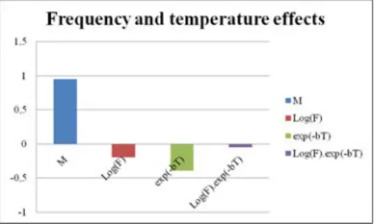
3) Frequency and temperature effects
While fixing the applied voltage at ±3 kV, the logarithm of the frequency and the exponential form of the temperature effects are presented in Fig.4., and the corresponding model is
Log(L) ~ 0.95—0.20*log(F)—0.39*exp(-bT)—
0.05*log(F) exp(-bT) (7)
The experimental result at the center of the level domain (i.e. V = ± 3kV, F = 8.7 kHz, T = 26.74 °C) shows that Log(L) = 0.88 which is very close to the theoretical value, i.e. 0.95 (only 7.8 % of error).
In these diagrams (i.e. Fig 2, 3 and 4), the first column represents the average value of the different experiments. The other columns show the influence of the different factors and
Figure 4. Factor and interaction effects of the frequency and temperature
interactions on the insulation lifetime with respect to the average value. These effect diagrams show that:
x The applied voltage and the temperature have
approximately the same effect on the insulation lifetime.
x The frequency effect on the insulation lifetime is much lower than the applied voltage and the temperature ones.
x The interactions between the different factors are small.
III. CONCLUSION
A brief description of the DoE statistical methodology has shown that this method could be extremely helpful to clarify the influence of parameters and their synergetic effects on the insulation ageing, a phenomenon known to involve many parameters. Results showed that the applied voltage and the temperature have a bigger influence on the insulation degradation rate than the frequency when the degradation is mainly due to a partial discharge activity.
In the beginning of our study, we had supposed that the variation of the logarithm of the insulation lifetime has an exponential form with the temperature. The correlation between the theoretical model and the experimental test at the center of the levels domain proved that our assumption is correct.
Our approach still in development, other ageing parameters should be taken into consideration in the next step. Moreover, we need to verify whether this method can be applied when the ageing is intrinsic and not due to partial discharges as in our experiments. Further explanation on this approach will be reported soon.
ACKNOWLEDGMENT
This work makes part of the PREMEP project. PREMEP is a national collaborative research project, approved by the Aerospace Valley pole and focused on the electric motors & electronics for aeronautical applications. The partners are Technofan, Liebherr Aerospace Toulouse, LAPLACE, CIRTEM, Ateliers de Navarre and DELTY.
REFERENCES
[1] N. Lahoud, L. Boudou and J. Martinez-Vega, “A multi-dimensional model to describe the ageing process of polymers used for electrical insulation”, Proc. 2007 IEEE ICSD, Winchester UK, pp. 79-82, 2007. [2] N. Lahoud, L. Boudou and J. Martinez-Vega, “A new approach to
describe the electrical ageing by considering the distributed nature of processes in polymeric materials,” J. Non-Cryst. Sol., vol. 356, pp. 652-656, 2010.
[3] M. Tanco, N. Costa and E. Viles, “Experimental design selection: guidelines for practitioners,” Int. J. Prod. Qual. Manag., vol. 4, no. 3, pp. 283-302, 2009.
[4] G. Stone, E.A. Boulter, I. Culbert and H. Dhirani, “Electrical insulation for rotating machines,” IEEE Press, J. Wiley & Sons, 2004.
[5] J. Faucher, P. Maussion, “On-line electrical quality improvement of a single-phase boost rectifier with fuzzy controller and experimental designs”, Electromotion, vol. 13, no 3, July – September 2006.