Publisher’s version / Version de l'éditeur:
Vous avez des questions? Nous pouvons vous aider. Pour communiquer directement avec un auteur, consultez la première page de la revue dans laquelle son article a été publié afin de trouver ses coordonnées. Si vous n’arrivez pas à les repérer, communiquez avec nous à [email protected].
Questions? Contact the NRC Publications Archive team at
[email protected]. If you wish to email the authors directly, please see the first page of the publication for their contact information.
https://publications-cnrc.canada.ca/fra/droits
L’accès à ce site Web et l’utilisation de son contenu sont assujettis aux conditions présentées dans le site
LISEZ CES CONDITIONS ATTENTIVEMENT AVANT D’UTILISER CE SITE WEB.
Paper (National Research Council of Canada. Division of Building Research); no.
DBR-P-1148, 1983
READ THESE TERMS AND CONDITIONS CAREFULLY BEFORE USING THIS WEBSITE. https://nrc-publications.canada.ca/eng/copyright
NRC Publications Archive Record / Notice des Archives des publications du CNRC :
https://nrc-publications.canada.ca/eng/view/object/?id=c29368ce-9971-4566-a591-5f2f5d0ce13a
https://publications-cnrc.canada.ca/fra/voir/objet/?id=c29368ce-9971-4566-a591-5f2f5d0ce13a
NRC Publications Archive
Archives des publications du CNRC
This publication could be one of several versions: author’s original, accepted manuscript or the publisher’s version. / La version de cette publication peut être l’une des suivantes : la version prépublication de l’auteur, la version acceptée du manuscrit ou la version de l’éditeur.
For the publisher’s version, please access the DOI link below./ Pour consulter la version de l’éditeur, utilisez le lien DOI ci-dessous.
https://doi.org/10.4224/40001786
Access and use of this website and the material on it are subject to the Terms and Conditions set forth at
Fire severity: basis of fire safety design
Ser
THl
no. 1
c .
2
National Research
Conseil national
Council Canada
de recherches Canada
BLDG
FIRE SEVERITY: BASIS OF FIRE SAFETY DESIGN
by T.Z. Harmathy
Reprinted from
Fire Safety of Concrete Structures,
American Concrete Institute, SPaO, 1983
p. 1 1 5 - 1 4 9
DBR Paper No. 1148
Division of Building Research
L e s c o n n a i s s a n c e s s c i e n t i f i q u e s du f e u s o n t s u f f i s a m m e n t avanc'ees, p o u r q u e l ' o n p u i s s e c o n c e v o i r l a s ' e c u r i t k - i n c e n d i e d a n s l e s b l t i m e n t s d ' a p r l d e s b a s e s t e c h n i q u e s p l u t a t q u ' a d m i n i s t r a t i v e s . B i e n q u e deux f a c t e u r s i m p o r t a n t s p o u r l a c o n c e p t i o n d e l a s ' e c u r i t k - i n c e n d i e , l a c h a r g e c o m b u s t i b l e e t l a v e n t i l a t i o n , s o i e n t d e s v a r i a b l e s al'eatoires, on p e u t t r o u v e r d e s v a l e u r s th'eoriques c o n s e r v a t r i c e s a p p l i c a b l e 6 B c e s f a c t e u r s , e n B t u d i a n t l e s v a l e u r s s t o c h a s t i q u e s e t l e s v a l e u r s e x t r h e s . Avec c e s v a l e u r s , l a c o n c e p t i o n d e l a s'ecurit'e- i n c e n d i e d e v i e n t p l e i n e m e n t d 6 t e r m i n i s t e .
La c o n c e p t i o n d e l a s B c u r i t ' e - i n c e n d i e comprend deux gl'hents: l a r M u c t i o n du p o t e n t i e l d e s t r u c t e u r du f e u , a u moyen d e p a r t i t i o n s ignifug'ees; e t l a r a u c t i o n d e s o n p o t e n t i e l d e p r o p a g a t i o n p a r c o n v e c t i o n , a u moyen d e p o r t e s 3 f e r m e t u r e a u t o m a t i q u e , d e t u y a u x c o n d u c t e u r s du f e u e t d e d ' e f l e c t e u r s d e flamme. Les e x i g e n c e s r e l a t i v e s
a
l a r h i s t a n c e a u f e u s o n t dBtermin'ees p a r l a c h a r g e t h e r m i q u e d e s p a r t i t i o n s , q u e l ' o n p e u t d a u i r e l o r s d e s r e c h e r c h e 6 d e c o n c e p t i o n . I1 e s t n g c e s s a i r e d e p r e n d r e c e r t a i n e s p r L a u t i o n s suppl'ementaires, l o r s q u e l ' o n examine l a performance a u f e u d e c e r t a i n s Blements-clBs d'un b l t i m e n t don&.SP
80-3
Fire Severity:
Basis
of Fire Safety
Design
By
T.2. hrmath
ySynopsis: Knowledge in fire science is sufficiently advanced to provide fire safety in buildings on the basis of engineering design rather than authoritative decisions. Although two important
factors in the design considerations, fire load and ventilation, are random variables, conservative design values for them can be found by stochastic and extreme value studies. With these values the design for fire safety is fully deterministic.
The design for fire safety has two components: countering the destructive spread potential of fire by the use of fire-resistant compartment boundaries, and countering its convective spread potential by the use of self-closing doors, fire drainage, and flame deflectors. The fire resistance requirements are determined by the normalized heat load on the compartment boundaries which is derived in the course of the design procedure. When dealing with the performance in fire of some key elements of the building, extra precautions are necessary.
Keywords: f i r e protection; f i r e resistance; f i r e s ; flames; f u e l s ;
heat capacity; safety f a c t o r ; structural design; thermal properties;
--
---
116
Harmathy
ACI member T.Z. Harmathy, head of the Fire Research Section, Division of Building Research, National Research Council Canada, has been active in ASTM Committee E-5 and ACI Committee
216
and is chairman of ASTM Subcommittee E05.32 on Research. He holds a 1 doctor of engineering degree from Vienna University of Technology.For the past several decades, fire-resistant compartmentation has been the most important component in the provision of fire safety. In the concept of fire-resistant compartmentation, a building is pictured as consisting of a number of compartments, all perfectly isolated from each other and from the rest of the
building, and therefore the spread of fire is assumed to take place by successive failure of the compartment boundaries. If the
compartment boundaries are fire resistant, it is claimed, failure will not occur and the size of fire will be kept within acceptable
limits.
The idea of a perfectly isolated compartment is a crude abstraction. Fire cannot develop in a fully isolated compartment; it must have access to air. In other words, the fire compartment must communicate with at least one other (inside or outside) space,
,
e.g., through an open door, a broken window, or any kind of ceiling or wall opening. Consequently, there must be at least one route along which the fire can also spread by convection: by the advance1
of flames and hot gases. A fire in a compartment, therefore, has two kinds of spread potential: destructive and convective.Observations over the last several decades have clearly shown that the potential for convective spread far outweighs the
potential for destructive spread. Yet the concept of I
fire-resistant compartmentation is concerned mainly with the I
problem of destructive spread potential, and with that in an I antiquated way, based on Ingberg's fire load concept (1) suggested ,
some 50 years ago. Aware of the questionable value of that concept, the writers of building codes usually increase the fire- resistant requirements beyond those yielded by Ingberg's concept, so that code requirements incorporate an unknown margin of safety. I
Based on advances made by fire science, it is now possible to place fire safety design on a coherent foundation. Such a
foundation will be outlined in this paper.
KEY ELEMENTS
AND
DIVIDING ELEMENTSIt is obvious that, from the point of view of the structural performance of the building as a whole during a fire, not all building elements are of equal importance. Some are parts of the
p r i n c i p a l s t r u c t u r a l network of t h e b u i l d i n g ; o t h e r s , a l t h o u g h t h e y may c a r r y a s u b s t a n t i a l l o a d , s e r v e mainly a s elements i n
s u b d i v i d i n g t h e b u i l d i n g i n t o compartments.
C o l l a p s e , o r even major d e f o r m a t i o n , of a key element may r e s u l t i n e x t e n s i v e damage and l o s s of l i f e ; i t must n o t be allowed t o happen even a f t e r a n e v e n t u a l s p r e a d of f i r e when t h e r e v e r s e s i d e of t h e element becomes exposed t o f i r e . It h a s been
suggested ( 2 ) t h a t t h e s t r u c t u r a l performance of a l l key e l e m e n t s be examined under f i r e exposure from b o t h s i d e s . T h i s i s
i n e v i t a b l y more d e t r i m e n t a l t h a n a n exposure from one s i d e o n l y , e s p e c i a l l y i f , a s u s u a l l y happens, f i r e on t h e r e v e r s e s i d e of t h e element s t a r t s a f t e r o r c l o s e t o t h e c e s s a t i o n of f i r e on i t s o b v e r s e s i d e .
*
The s t r u c t u r a l performance of d i v i d i n g elements i n f i r e i s much l e s s c r i t i c a l . Once a n expanding f i r e h a s reached t h e
r e v e r s e s i d e of a d i v i d i n g e l e m e n t , i t s s t r u c t u r a l f a i l u r e can i n no way i n f l u e n c e e i t h e r t h e f u r t h e r c o u r s e of t h e f i r e o r t h e performance of t h e b u i l d i n g a s a whole. E v a l u a t i n g t h e performance of d i v i d i n g e l e m e n t s by p i c t u r i n g t h e f i r e a s o c c u r r i n g on one s i d e only ( a s i t i s p i c t u r e d i n t h e p r e v a i l i n g f i r e t e s t i n g p h i l o s ~ p h y ) i s t h e r e f o r e adequate.
FIRE LOAD
The p r i n c i p a l d i f f i c u l t y i n c a l c u l a t i n g t h e expected s e v e r i t y of compartment f i r e s i s t h a t t h e two most i m p o r t a n t i n p u t
v a r i a b l e s , f i r e l o a d and v e n t i l a t i o n , a r e random v a r i a b l e s . T r a d i t i o n a l l y , t h e combustible c o n t e n t s of compartments a r e q u a n t i f i e d i n terms of s p e c i f i c f i r e l o a d which i s d e f i n e d a s t h e mass of c o n v e n t i o n a l combustibles ( c e l l u l o s i c s ) p e r u n i t f l o o r
!
a r e a . I f n o n - c e l l u l o s i c s a r e a l s o p r e s e n t , t h e i r mass i s converted i n t o c a l o r i f i c a l l y e q u i v a l e n t e q u i v a l e n t mass of wood by t h e a p p l i c a t i o n of t h e m u l t i p l i e r A H f / ~ Q , where AHf i s t h e h e a t of combustion of t h e n o n - c e l l u l o s i c f u e l and AHw t h a t of wood.Surveys i n d i c a t e d t h a t t h e type of occupancy i s t h e most i m p o r t a n t f a c t o r i n t h e magnitude of t h e s p e c i f i c f i r e load. It was a l s o found, however, t h a t even f o r s i m i l a r occupancies t h e s p e c i f i c f i r e l o a d may vary markedly i n a n u n p r e d i c t a b l e f a s h i o n .
L i s t e d i n T a b l e 1 a r e some d a t a on t h e s t a t i s t i c a l median of t h e s p e c i f i c f i r e l o a d , I,,,. They were c a l c u l a t e d from t h e r e s u l t s
*
U n f o r t u n a t e l y , s t r u c t u r a l performance of key e l e m e n t s i n a two-sided f i r e exposure cannot be a s s e s s e d from t h e r e s u l t s of s t a n d a r d f i r e tests a s they a r e performed today. The p o s s i b i l i t y of r e w r i t i n g t h e test method t o a l l o w f o r t h e f i r e exposure of t h e t e s t specimens from b o t h s i d e s i s being c o n s i d e r e d by a t a s k group of ASTM E05.of f i r e load surveys i n Sweden (3). For o f f i c e rooms t h e Swedish r e s u l t s have been c o r r o b o r a t e d by d a t a published i n t h e
United Kingdom ( 4 ) . A r e c e n t survey i n t h e United S t a t e s ( 5 ) seems t o i n d i c a t e , however, t h a t o f f i c e f i r e l o a d s may be h i g h e r i n North America.
The s u b s t a n t i a l v a r i a b i l i t y of t h e s p e c i f i c f i r e load p r e s e n t s a problem i n s e l e c t i n g i t s v a l u e s f o r f i r e s a f e t y design. I f t h e median is chosen, t h e d e s i g n may be inadequate i n h a l f t h e c a s e s ; i f a value m c h h i g h e r t h a n t h e median i s s e l e c t e d , t h e c o s t of f i r e p r o t e c t i o n may be unduly i n c r e a s e d . It has been suggested i n Sweden t h a t t h e d e s i g n of f i r e s a f e t y be based on t h e
8 0 t h p e r c e n t i l e s , LBO, i n t h e a p p l i c a b l e cumulative p l o t s of s p e c i f i c f i r e l o a d ( a l s o l i s t e d i n Table 1).
Choosing L8() appears t o be a c c e p t a b l e i n t h e d e s i g n of d i v i d i n g elements. When d e a l i n g w i t h a b u i l d i n g ' s key elements, however, i t aeems a d v i s a b l e t o a l l o c a t e some a d d i t i o n a l margin of s a f e t y . L i e claimed t h a t t h e d e s i g n v a l u e of s p e c i f i c f i r e l o a d be regarded a s a v a r i a b l e and s e l e c t e d i n such a way a s t o minimize t h e o v e r a l l monetary l o s s e s ( r e l a t e d t o both f i r e and f i r e p r o t e c t i o n ) , w i t h t h e s a f e t y of t h e occupants a l s o t a k e n i n t o c o n s i d e r a t i o n (6). S i n c e s i z a b l e monetary l o s s e s a r e a s s o c i a t e d with t h e f a i l u r e of key elements, t h e u t i l i t y of t h i s concept i s p r i m a r i l y i n t h e d e s i g n of key elements f o r f i r e s a f e t y .
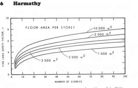
L i e recommended t h a t t h e d e s i g n value of t h e s p e c i f i c f i r e l o a d be expresed a s a product of t h e s t a t i s t i c a l median, L,,,, and a s a f e t y f a c t o r , s. On s t o c h a s t i c c o n s i d e r a t i o n s , he c a l c u l a t e d t h e s a f e t y f a c t o r a s a f u n c t i o n of f l o o r a r e a and b u i l d i n g h e i g h t . The r e s u l t s a r e summarized i n Fig. 1."
I n view of t h e preceding c o n s i d e r a t i o n s , an ' e q u i v a l e n t ' design f i r e l o a d , Ge, can be c a l c u l a t e d from t h e f o l l o w i n g formulae: AFLSO f o r d i v i d i n g elements A F s L , f o r key elements ( l a ) ( l b ) where AF is t h e f l o o r a r e a of t h e compartment. It f o l l o w s from t h e d e f i n i t i o n of t h e s p e c i f i c f i r e load t h a t t h e a c t u a l d e s i g n f i r e load, G, i s e q u a l t o Ge only i f t h e combustibles c o n s i s t e n t i r e l y of c e l l u l o s i c s . I f , a s u s u a l , small amounts of n o n - c e l l u l o s i c s a r e a l s o p r e s e n t , t h e f i r e w i l l on t h e whole s t i l l behave ( a s w i l l be pointed out l a t e r ) a s a f i r e of
*
Although t h e c o n t e n t s of Fig. 1 r e f l e c t a c o r r e c t philosophy i n s p e c i f y i n g d e s i g n v a l u e s f o r t h e f i r e l o a d , t h e course of t h e curves may r e q u i r e some r e v i s i o n i n f u t u r e when f u r t h e r s t a t i s t i c a l d a t a become a v a i l a b l e .Fire
Safety Design
119
all-cellulosics. This being so, Ge can be regarded as representing the actual (assumedly all-cellulosic) fire load. If, however, the combustibles consist entirely or predominantly of non-cellulosics, the fire may assume entirely different characteristics. In
calculating these characteristics, the actual design fire load, G, is the input information needed which is different from the
equivalent design fire load, Ge. The following equations apply:
if the combustibles consist wholly or
predominantly of cellulosics (2a)
if the combustibles are non-cellulosics (2b)
(Knowing the design fire load and heat of combustion of fuel, the designer can place an upper limit on the "normalized heat load" on the compartment which, as will be discussed later, is the measure of the potential of fire to spread by destruction.)
VENTILATION OF FIRES
In evaluating the results of compartment burn-out tests, it has been usual to assume that the ventilation of the compartment is determined by the dimensions of the ventilation opening. This assumption is tenable only if the compartment connnunicates with (receives air from and discharges hot fire gases to) a single environment (Fig. 2a). Under such classic conditions the flow rate of air can be expressed approximately as (7):
where 8* is the ventilation parameter,
pa is the density of atmospheric air, A V the area of ventilation opening (window, door), hV the height of the opening, g the
acceleration due to gravity, and
R the rate of consumption of fuel
mass by gasification (pyrolysis or vaporization), often referred to as "rate of burning".x
is a factor 0 1 ) which accounts for the coupling by the fire plume between the streams of air and hot fire gases.Unfortunately, real-world fires are rarely of the classic type.
A compartment on fire almost always has some secondary
routes of communication with one or more secondary environments. The ventilation of the compartment is, as a rule, draft modified (Figs. 2 b to e). If the secondary routes of communication arel a r g e , a c r o s s - d r a f t may develop, and t h e v e n t i l a t i o n of t h e compartment may i n c r e a s e by a f a c t o r of 5 o r more i n comparison w i t h t h e c l a s s i c , d r a f t - f r e e case. I n t h i s l i g h t t h e flow r a t e of a i r determined by t h e v e n t i l a t i o n parameter,
a*,
and, based on t h a t , by t h e dimensions of t h e v e n t i l a t i o n opening, can be regarded a s j u s t about t h e minimum t h a t can occur i n real-world f i r e s :where Ua i s t h e flow r a t e of a i r determined by a p r e s s u r e
d i s t r i b u t i o n c r e a t e d by t h e f i r e i n t h e compartment and modified by t h e p r e s s u r e d i s t r i b u t i o n t h a t would e x i s t i n t h e absence of f i r e .
The form of Eq. ( 3 ) a p p l i c a b l e t o real-world f i r e s i s a s f o l l o w s :
where @ i s now a random v a r i a b l e , t o be r e f e r r e d t o a s " v e n t i l a t i o n f a c t o r , " f o r which, by v i r t u e of Eq. ( 5 ) , t h e lower bound i s
a*:
It w i l l be s e e n t h a t t h e e x i s t e n c e of a lower bound i s very convenient because i t e l i m i n a t e s t h e need f o r s t a t i s t i c a l c o n s i d e r a t i o n s i n t h e s e l e c t i o n of a d e s i g n v a l u e f o r t h e v e n t i l a t i o n f a c t o r .
FIRE SEVERITY PARAMETERS
Since d e s t r u c t i v e and c o n v e c t i v e f i r e s p r e a d i s most l i k e l y t o occur d u r i n g t h e p e r i o d of f u l l f i r e development, when 80 t o
95 percent of t h e f u e l energy i s r e l e a s e d , t h e c o n d i t i o n s a r i s i n g i n t h e compartment d u r i n g t h e p e r i o d of f u l l f i r e development a r e of foremost i n t e r e s t i n t h e d e s i g n f o r f i r e s a f e t y .
The term " f i r e s e v e r i t y " u s u a l l y has d i f f e r e n t c o n n o t a t i o n s f o r d i f f e r e n t r e s e a r c h e r s . Its c o r r e c t i n t e r p r e t a t i o n comes from an examination of t h e dependent v a r i a b l e s of t h e f i r e process. T h e i r number obviously e q u a l s t h e number of independent e q u a t i o n s needed t o d e s c r i b e t h e f i r e process. Host can be formulated i n two ways: they may d e s c r i b e e i t h e r momentary c o n d i t i o n s , o r average c o n d i t i o n s c h a r a c t e r i s t i c of t h e whole d u r a t i o n of f u l l y developed f i r e . It i s b e l i e v e d t h a t t h e n a t u r e of t h e problem does n o t warrant more r e a l i s m than t h a t provided by d e s c r i b i n g t h e average c o n d i t i o n s .
Three energy balances can be s e t up f o r t h e p r o c e s s . The f i r s t , w r i t t e n over t h e v e n t i l a t i o n opening, o f f e r s i t s e l f f o r e x p r e s s i n g t h e o v e r a l l p e n e t r a t i o n f l u x , {, t h a t i s , t h e h e a t f l u x absorbed by t h e compartment boundaries, averaged o v e r a l l
boundaries, and temporally over t h e p e r i o d of f u l l f i r e development. T h i s e x p r e s s i o n i s of t h e form
-
q = f ( ~ , , R , Q, Tg, I f u e l ' , 'compartment') (8)
where Q i s t h e ( a v e r a g e ) r a t e of e v o l u t i o n of energy from t h e f u e l w i t h i n t h e compartment, and T t h e average temperature of t h e compartment g a s e s (average ' & r e temperature' )
,
averaged over t h e 1 compartment volume and temporally over t h e period of f u l l f i r edevelopment. 'Fuel' and 'compartment' a r e t h e independent o r i n p u t v a r i a b l e s . ' F u e l ' s t a n d s f o r t h e thermodynamic and geometric v a r i a b l e s t h a t c h a r a c t e r i z e t h e f u e l ; 'compartment' s t a n d s f o r t h e geometric v a r i a b l e s o r thermal p r o p e r t i e s t h a t c h a r a c t e r i z e t h e compartment o r i t s s u r f a c e m a t e r i a l s .
The second energy b a l a n c e , t h a t over t h e s u r f a c e of t h e compartment, can be used i n t h e form of an e x p r e s s i o n f o r
T
g:
Tg = f({, T , 'compartment') ( 9 )
where T i s t h e d u r a t i o n of f u l l y developed f i r e .
The t h i r d energy balance, t h a t over t h e f u e l s u r f a c e , o f f e r s i t s e l f f o r an e x p r e s s i o n f o r t h e r a t e of consumption of t h e f u e l mass by g a s i f i c a t i o n ( ' r a t e of b u r n i n g ' ) i n t h e form
1
R = f ( T g , ' f u e l ' ) (10)I A s w i l l be d i s c u s s e d l a t e r , t h i s t h i r d energy balance i s n o t needed i f t h e r a t e of g a s i f i c a t i o n of t h e f u e l can be d e s c r i b e d i n some o t h e r way, f o r example by e m p i r i c a l e q u a t i o n s .
Another e q u a t i o n can be w r i t t e n f o r t h e ( a v e r a g e ) r a t e of
i
e v o l u t i o n of energy from t h e f u e l w i t h i n t h e compartment,Q = f(Ua, R, ' f u e l ' , 'compartment') ( 1 1 ) Then t h e r e is a simple e x p r e s s i o n f o r t h e d u r a t i o n of f u l l y developed f i r e ,
1
Equation ( 6 ) f o r t h e f l b r r a t e of a i r should be added t o t h e above equations.Ua, R, Q ,
Tg,
and T a r e t h e dependent o r p r o c e s s v a r i a b l e s . A l l but t h e l a s t r e p r e s e n t time-averaged v a l u e s over t h e p e r i o d of f u l l f i r e development. ForT
andq
t h i s f a c t i s emphasized by t h e u s e of a b a r above t h e symbol! For s i m p l i c i t y , t h e u s e of t h e b a r has been dispensed w i t h when d e a l i n g w i t h Q, Ua and R.- -
An examination of t h e s i x process v a r i a b l e s r e v e a l s t h a t o n l y Tgs q , and T b e a r d i r e c t r e l a t i o n t o t h e n a t u r e of f i r e . They a r e r e f e r r e d t o a s ' f i r e s e v e r i t y parameters'. Even f u r t h e r , of t h e s e t h r e e e i t h e rT
and T , o rq
and T a r e s u f f i c i e n t f o r f u l l y g c h a r a c t e r i z i n g t h e f i r e process. I fT
and T a r e s e l e c t e d , t h e c h a r a c t e r i z a t i o n is done from t h e p o i n f of view of t h e f i r e i t s e l f , whereas i f and T a r e chosen, t h e e f f e c t of f i r e on t h ecompartment boundaries, i n o t h e r words, i t s d e s t r u c t i v e p o t e n t i a l ,
is emphasized.
POTENTIALS FOR DESTRUCTUVE AND CONVECTIVE SPREADS
As language conveys t h e i d e a of t h e p o t e n t i a l of f i r e f o r d e s t r u c t i v e s p r e a d by a s i n g l e e x p r e s s i o n , f i r e s e v e r i t y , i t h a s always seemed d e s i r a b l e t o have a s i n g l e v a r i a b l e t o r e p r e s e n t i t
numerically. I n v e s t i g a t i o n s have shown (8) t h a t f o r r e i n f o r c e d and p r e s t r e s s e d c o n c r e t e compartment boundaries, and p o s s i b l y many o t h e r typesl a s i n g l e d e s c r i p t o r , t h e product formed by t h e two
parameters q and T , i s capable of a more o r l e s s unique
c h a r a c t e r i z a t i o n of t h e s e v e r i t y of f i r e , i r r e s p e c t i v e of t h e
temperature h i s t o r y of t h e f i r e gases. The product q~ can be
recognized a s q u a n t i f y i n g t h e t o t a l h e a t a b s o r p t i o n p e r u n i t s u r f a c e of t h e boundaries d u r i n g t h e p e r i o d of f u l l f i r e development. It w i l l be r e f e r r e d t o a s o v e r - a l l h e a t load.*
Although h e a t load i s an a p t d e s c r i p t o r of t h e r e l a t i v e s e v e r i t y of f i r e s i n a g i v e n e n c l o s u r e , i t i s n o t a parameter t h a t can be used t o compare t h e s e v e r i t y of f i r e s o c c u r r i n g i n u n l i k e e n c l o s u r e s . Take, f o r example, two f i r e s , one i n e n c l o s u r e A,
which is l i n e d with f a i r l y good conductors ( i . e . , w i t h m a t e r i a l s of high thermal i n e r t i a ) , and t h e o t h e r i n e n c l o s u r e B, l i n e d w i t h i n s u l a t o r s (i.e., m a t e r i a l s of low thermal i n e r t i a ) . Assume t h a t t h e h e a t load on t h e boundaries of b o t h e n c l o s u r e s is t h e same. C l e a r l y , it t a k e s f i r e s of two d i f f e r e n t s e v e r i t i e s t o d r i v e t h e same amount of h e a t ( p e r u n i t s u r f a c e a r e a ) i n t o t h e boundaries of e n c l o s u r e s A and B.
The problem of how t o compare f i r e s i n u n l i k e e n c l o s u r e s from t h e p o i n t of view of t h e i r p o t e n t i a l s f o r d e s t r u c t i o n h a s
e s s e n t i a l l y been solved by t h e i n t r o d u c t i o n of t h e concept of "normalized h e a t load" (9). The normalized h e a t load, H, i s defined a s
*
Note t h a t f o r u n p r o t e c t e d s t e e l c o n s t r u c t i o n s t h e o v e r - a l l h e a t load is not an adequate measure of f i r e s e v e r i t y .where
&
is the thermal inertia of the enclosure boundaries, k is thermal conductivity, p is density, and c is specific heat. In words: the normalized heat load is the heat load referred to the thermal inertia of the enclosure.As mentioned earlier, fires rarely spread by structural destruction. The most common mechanism of spread is the spilling out of the uncombusted products of fuel gasification, carrying flames into the spaces surrounding the compartment on fire. Clearly, fuels and conditions conducive to massive combustion of
)
fuel volatiles outside the compartment boundaries present a very real danger from the point of view of fire spread.A
factor has been introduced to characterize the convective spread potential of fire (7). It is denoted by p and defined as the ratiorate of heat evolution outside fire compartment
( 1 4 )
IJ =
total rate of heat evolution from fuel
Once the calculation of the fire severity parameters is completed, the u-factor can be calculated from the spin-off data.
EFFECT OF COMPARTMENT SURFACE MATERIALS
1 As already indicated, the thermal properties of the
compartment surface materials enter the problem of characterizing the fire process via the group
6.
If, as usual, the various boundaries of the compartment are formed by different materials,6
represents the over-all thermal inertia for the compartment surfaces which is the weighted average of the thermal inertias forI the individual boundaries. For a compartment formed by n boundary
surfaces,
where
where the subscript i (= 1, 2,
. .
.
n) refers to the various surf ace materials as well as the boundary surf aces formed by them.Typical values for the thermal properties of a few common building materials are listed in Table 2.
The over-all penetration heat flux,
q,
can be expressed-
analogously as the weighted average of the heat fluxes, qi,penetrating the individual boundaries:
After multiplying Eq. (15) by
y/dkpc
and deducting the result from Eq. (17), one gets a homogeneous linear equation, the trivial solution of which is*:Clearly, like the over-all penetration flux, s, the individual penetration fluxes,
ii
(qi, q2,.
.
.
in)
are also temporal averages taken over the period of full fire development.It follows from Eq. (18) that the heat loads on the individual compartment boundaries are related to the over-all heat load as
-
-
92=
a "- -
- . . .
qd
=2
-
= H (19)/=
(kpcJ
n n n(The signs of approximate equation are used to call attention to the fact that conclusions based on the trivial solution are only of approximate validity.)
Equation (19) is referred to as the theorem of uniformity of normalized heat load.
CHARACTERISTICS OF FIRES OF NON-CHARRING FUELS
Non-charring fuels include all liquid fuels and the majority of common plastics. With liquids fuels, the fuel is usually present in the form of a pool on the floor of the compartment. There are a few non-charring plastics, including polyethylene, polypropylene, and polystryene, whose melting point is lower than the pyrolysis temperature. If these plastics are present in a compartment in quantities substantial enough to survive into the period of full fire development, they will probably also assemble into a pool on the compartment floor.
*
It has been found (9) that the conditions characterized by the trivial solution are closely approximated after a transitional period.Fire
Safety Design
la5
S o l i d s t h a t t e n d t o r e t a i n t h e i r o r i g i n a l s h a p e i n f i r e w i l l be consumed i n some complex c o n f i g u r a t i o n , u s u a l l y comprising many s e l f - v i e w i n g s u r f a c e s . Any of t h e s e c o n f i g u r a t i o n s w i l l be r e f e r r e d t o a s ' p i l e ' . S i n c e p i l e - b u r n i n g g r e a t l y adds t o t h e complexity of t h e p r o c e s s , i t i s u n d e r s t a n d a b l e t h a t e x p e r i m e n t a l f i r e s of non-charring f u e l s have s o f a r been conducted only on pool-like c o n f i g u r a t i o n s (10, 11, 1 2 ) .
E x p l i c i t forms of Eqs. (8) t o (11) and ( 1 4 ) , a s a p p l i c a b l e t o p o o l f i r e s of non-charring f u e l s , have been d e r i v e d e l s e w h e r e (7) and w i l l be reproduced h e r e w i t h o n l y a minimum of e x p l a n a t i o n .
The developed form of Eq. (8) i s
I n t h i s e q u a t i o n , Ta i s t h e t e m p e r a t u r e of a i r e n t e r i n g t h e f i r e compartment, u s u a l l y t a k e n a s 293.2 K. T is t h e t e m p e r a t u r e of g a s i E i c a t i o n ( p y r o l y s i s o r
vaporization),'^^
t h e h e a t ofP
g a s i f i c a t i o n , and
c
t h e a v e r a g e s p e c i f i c h e a t of t h e f i r e gases.A i s t h e t o t a l bouEdary s u r f a c e of t h e compartment and
Ap
t h e a r e aOF
f u e l pool.a
i s t h e Stefan-Boltzmann c o n s t a n t .The f i r s t , t h i r d and f o u r t h terms w i t h i n t h e b r a c e s r e p r e s e n t , r e s p e c t i v e l y , t h e r a t e of h e a t e v o l u t i o n w i t h i n t h e compartment, t h e r a t e of r a d i a n t h e a t l o s s through t h e v e n t i l a t i o n opening, and t h e r a t e of h e a t a b s o r p t i o n i n t h e g a s i f i c a t i o n of t h e f u e l .
The second term w i t h i n t h e b r a c e s r e p r e s e n t s t h e c o n v e c t i v e h e a t l o s s by t h e compartment. It i s based on t h e assumption t h a t t h e r e f e r e n c e t e m p e r a t u r e l e v e l f o r e n t h a l p y g a i n by t h e
compartment g a s e s i s roughly halfway between t h e i n l e t a f r
t e m p e r a t u r e , and t h e t e m p e r a t u r e of f u e l g a s i f i c a t i o n . c depends g on t h e r a t i o of t h e combustion p r o d u c t s t o t h e y e t uncombusted p y r o l y s i s p r o d u c t s i n t h e e f f l u e n t g a s e s . Although i t s v a l u e c a n be approximated by i t e r a t i o n ( 7 ) , i t i s normally s a t i s f a c t o r y t o assume f o r
c
an "all-purpose" v a l u e , 10 t o 30 p e r c e n t h i g h e r t h a n g t h e s p e c i f i c h e a t of n i t r o g e n .The e x p l i c i t form of Eq. ( 9 ) i s ( 1 3 )
where
6,
t h e o v e r - a l l thermal i n e r t i a f o r t h e compartment, c a n be o b t a i n e d from Eq. ( 1 5 ) , andn2
i s an e m p i r i c a l f a c t o r w i t h a v a l u e of about 0.9. T h i s e q u a t i o n a p p a r e n t l y does n o t c o n t a i n anyvariable that would restrict its validity to any particular type of fuel; it is indeed valid for fires involving either non-charring or charforming fuels, or both.
For non-charring fuels, Eq. (10) assumes the following explicit form:
In this equation 6 represents the fraction of the pool area, Ap, I
which, under the effect of higher radiant heat fluxes from the flame zone (see Fig. 2a in Ref. 7) undergoes vigorous gasification, whereas along a (1-6) fraction of the pool area the gasification is
somewhat more subdued. f3Ap can be estimated roughly as a 1 m deep strip from the pool area on the side of the air entry.
($T
(($ 1 1 ) is the temperature in the flame zone which is expectedg
to be somewhat higher than the average temperature of the compartment gases.
n1
is another empirical factor influenced largely by the emissivity of the pool and the fire gases. Clearly, in the formulation of Eq. (22) it was assumed that the heatexchange between the pool and the fire gases takes place predominantly by radiation. This assumption is indeed a fair approximation of the facts.
Equation (11) will take the following form: Y U ~ S A H ~ I ~
Q = (
whichever is lessyRSAHv
Here the factor 5 (41) takes account of the fact that, owing to the formation of CO and soot during combustion, and to dissociation,
the actual heat of combustion is less than the theoretical value. 1 The other factor, y (<I) accounts for combustion deficiency due to
incomplete mixing.
\
Finally, the explicit form for Eq. (14) is
Six equations, namely Eqs. ( 6 ) , (12), and (20) to (23), are I
now-available for calculation of the six process variables, Ua,
R,
Q, Tg, q, and T. The calculations can be performed on a
programmable desk calculator, following the iterative scheme s h m n in Fig.
3.
Once the process variables are known, the normalized heat load (potential for destructive spread, Eq. (13)),H,
and the v-factor (potential for convective spread, Eq. (24)) can also be calculated.To explore the effect of ventilation (a random variable) on the potentials for destructive spread and convective spread, series
of calculations were performed on hypothetical pool fires. The thermodynamic properties of the pool material were assumed to be similar to those of polymethyl-methacrylate (PMMA), and the fire compartment similar to that described by Butcher et al. (14, 15) in their papers on their full-scale burn experiments. Three pool sizes were studied, occupying 100, 50 and 25 percent of the floor area, representing three (equivalent) design fire loads,
Ge/AF = 60, 30, and 15 kg m-*. The input information used in the calculations is listed in Table 3. As indicated there, several of the values can be regarded as typical under full-scale conditions.
!
The results of the calculations are presented graphically inFig. 4 in such a form as to show the effect of ventilation on the potentials for destructive spread, H, and convective spread, p .
The following observations can be made:
(i) The destructive spread potential of pool fires (as
represented by H), is not a strong function of the fire load, because with an increase in the fire load an increasing portion of the fuel energy is released outside the fire compartment. Thus the danger of storing large amounts of pool-forming materials in a compartment lies not so much in the damage that the fire can cause to the compartment itself, as in the damage that it can bring about in the surrounding building spaces.
I (ii) Both the destructive spread potential (H) and the convective
spread potential
(u)
decrease slightly with increasing ventilation.The latter finding is rather reassuring in the light of Eq. (7). It suggests that a safe design can be achieved by using for 8 the ventilation parameter,
a*
(zPdV
j-),
see Eq. (4)).I With the information listed in Table 3, 8* can be calculated
as 28.6 kg s-l. The pertaining values of H and p are marked with arrows in Fig. 4. Clearly, at any fire load, the potentials for destructive spread and convective spread are expected to decrease if for any reason, e.g., due to cross draft, 8 assumes a value higher than 28.6 kg s-l
.
I Pile fires differ from pool fires in several ways.
A
pileacts as a primitive air-entraining and volatile-air premixing device, tending to produce hotter flames than pool fires. In addition, the fuel surface that sees the flames is larger, so that the rate of production of volatile pyrolysis products by a pile is much larger than that by a pool of the same material and base area. In a series of experiments performed on a non-charring kind of plastic the author found that the rate of pyrolysis of cross-cribs of the material was 3.7 to 5.4 times higher than that of a slab (which is an idealized 'pool') of the same base area. Being unable to come into contact with sufficient amounts of air within the compartment, a greatly increased portion of the pyrolysis products are forced to burn outside the compartment. In the compartment
itself, the temperature remains moderate and the conditions are conducive to strong soot formation. It is clear, therefore, that the principal danger in fires involving large quantities of
non-charring fuels is the enhanced potential for spread of fire and smoke through the building.
CHARACTERISTICS OF FIRES OF CHARRING FUELS
Cellulosics and other char-forming fuels cannot normally support fire in a pool configuration. In most of the experiments with fully-developed fires of cellulosics, piles of wood sticks usually arranged in a crib configuration were used as fuel.
According to recent surveys, the fire load in residential and off ice buildings still consists predominantly of cellulosic
materials. That being so, attention in this paper will be focused on fires of cellulosics, wood in particular.
It was among the most important discoveries of fire science that, at low ventilation, the rate of consumption of the mass of wood piles in fire is roughly proportional to the rate of inflow of air, whereas at higher ventilations it is proportional to the surface area of the fuel (16). The extent of the two regimes, commonly referred to as ventilation-controlled and
fuel-surface-controlled regimes, respectively, and the point of transition between them was determined from a plot of some 250 experimental data.
The following empirical equations were obtained (13):
Here 'i' is the specific surface area of the fuel. (For conventional furniture = 0.13 m2 kg-1 .) Equation (25a) applies to the
ventilation-controlled, Eq. (25b) to the fuel-surface-controlled regime.
(YG
is equal to the surface area of the fuel.) The reason for the existence of these two regimes is explained elsewhere in detail (7).The fact that the value of the rate of consumption of fuel need not be derived from an energy balance over the fuel surface (such as Eq. (10)) but is obtained directly from Eq. (25a) or (25b), translates into the claim that the rate of consumption of fuel is not coupled with any of the other process variables except air-flow rate. Since with non-charring plastics the rate of consumption of fuel can never be decoupled from the other process variables, the feasibility of such decoupling for cellulosics must be attributed to the fact that they are char-forming materials. Indeed, it has been proved by specially devised tests
(17)
that theFiresafety
Design
129
char t h a t covers t h e s u r f a c e of c e l l u l o s i c s , and char-formingm a t e r i a l s i n g e n e r a l , i s i n s t r u m e n t a l i n t h e unique coupling of R and @ ( o r Ua). The air-flow f e e d s t h e o x i d a t i o n of c h a r , which i n t u r n provides t h e h e a t t h a t d r i v e s t h e p y r o l y s i s . I n b r i e f , t h e s e f u e l s have a b u i l t - i n h e a t supply mechanism f o r p y r o l y s i s , and t h e r e f o r e t h e i r r a t e of consumption by p y r o l y s i s depends t o a much l e s s e r e x t e n t on t h e thermal c o n d i t i o n s p r e v a i l i n g i n t h e compartment t h a n i t does i n t h e c a s e of non-charring f u e l s .
A s a l r e a d y mentioned, t h e e x p r e s s i o n f o r
T
given by Eq. (21) (an e x p l i c i t form of Eq. ( 9 ) ) , i s g e n e r a l l y v a l f d , r e g a r d l e s s of t h e n a t u r e of f u e l . Equation (12) f o r T i s a l s o e s s e n t i a l l yindependent of t h e n a t u r e of fuel*. Since an e q u a t i o n f o r t h e r a t e of g a s i f i c a t i o n has been d e r i v e d f o r c e l l u l o s i c s on e m p i r i c a l grounds, without r e s o r t t o a h e a t balance over t h e f u e l s u r f a c e (such a s Eq. ( l o ) ) , a l l t h a t remains now i s t o f i n d t h e e x p l i c i t forms of Eqs. ( 8 ) and ( l l ) , a p p l i c a b l e t o c e l l u l o s i c s .
The e x p l i c i t form of Eq. ( 8 ) i s
and t h a t of Eq. (11)
I n Eq. (26) t h e import of t h e v a r i o u s terms i n t h e b r a c e s i s t h e same a s t h a t of t h e corresponding terms i n Eq. (20). v i s an e m p i r i c a l f a c t o r with a value of about 1.05 which accounts f o r t h e s l i g h t s p a c i a l non-uniformity of t h e temperature of t h e f i r e gases.
-
c i s a g a i n t h e s p e c i f i c h e a t of t h e f i r e gases t h e bulk of which g
i s made up of n i t r o g e n . A s , when d e a l i n g w i t h c e l l u l o s i c s , AH,, is a very small ( p o s i t i v e o r n e g a t i v e ) q u a n t i t y , t h e l a s t term can be dropped from Eq. (26).
The meaning of t h e numerical c o n s t a n t s i n Eq. (27) i s explained i n Ref. (13).
I
Equation (27) c o n s i s t s of two terms, r e f l e c t i n g t h a t t h e e v o l u t i o n of h e a t i n t h e compartment i s a t t r i b u t a b l e p a r t l y t o t h e combustion of t h e v o l a t i l e products of p y r o l y s i s , and p a r t l y t o t h e o x i d a t i o n of t h e c h a r . r e s i d u e (13). AHc i s t h e h e a t of o x i d a t i o n of char. By i n c l u d i n g t h e f a c t o r 6 ( < I ) , account i s taken of t h e
*
I n some of h i s previous papers t h e a u t h o r , t o t a k e account of t h e f a c t t h a t t h e o x i d a t i o n of c h a r always extends beyond t h e period of f u l l f i r e development, used a s l i g h t l y c o r r e c t e d form of Eq. (12) f o r c e l l u l o s i c s . The c o r r e c t i o n , however, i s i n s i g n i f i c a n t and w i l l be n e g l e c t e d here.fact that, in general, only part of the heat of combustion of the volatile decomposition products is released inside the
compartment.
Since the stoichiometric air requirement for the volatiles of wood is rather small, r 4.2, and the ratio of air flow to
volatile production, U /R, is never less than 5.3 (as can be proved
by combining Eqs. (25af and ( 6 ) , taking
x
>
l), there seems to be no reason why the combustion of volatiles should continue outside the compartment. Yet is is well-known that, even under fuel- surface-controlled conditions (for which Ua/
R ~ 5 . 3 1 , flames usually issue through the ventilation opening.In examining a large number of experimental data, the author found that the height of the compartment has an important bearing on whether the combustion will continue outside the ventilation opening. The following empirical equations have been suggested:
They yield conclusions in reasonable agreement with those offered by the experiments of Butcher et al. (14, 15).
a
is a hypothetical flame height, to be calculated asOnce the process variables are known, the potential for convective spread can be expressed as
This equation follows from the definition equation for p (Eq. 14)) and from Eq. (27).
Figure 5 shows the scheme for calculating the six process variables. Owing to the fact that the rate of consumption of fuel by pyrolysis. R, is obtained directly from input data (see
Eqs. (25a) and (25b)), the values of three more of the process variables, namely Ua, T, and Q, can be ca_lculated without iteration. However, the calculation of q and
T
still requiresiteration. g
Again, to explore the effect of ventilation on the potentials for destructive and convective spread, a series of calculations were performed on fires of cellulosics occurring in a compartment
identical with that described earlier. The design fire load, Ge/AF, was again selected as 60, 30, and 15 kg nr2. These calculations simulated actual full-scale burnout experiments performed by Butcher et al.
(14,
15). Similar calculations performed earlier and slightly differently (13) showed good agreement between experimental and theoretical results.The input information used in the calculations is listed in Table 4 . The results of the calculations have been plotted
(Fig. 6) to show the effect of ventilation on the potentials for destructive spread, H, and convective spread,
u.
The following conclusions can be drawn:
(i) The destructive spread potential of cellulosic fires (as represented by H) is, under real-world fire conditions,
usually much higher than that for fires of non-charring materials, and is a strong function of the fire load. At any fire load, it decreases rapidly with increasing ventilation.
(ti) The convective spread potential (as represented by the u-factor) comes nowhere near that characterizing non-charring fires. It is also a strong function of the fire load and increases with increasing ventilation.
The fact that H decreases with increasing ventilation is again reassuring. It allows measures to counter the destructive spread of fire to b e a s e d on calculations performed by selecting
O*
(zPgV
/
ghV)
which, according to Eq. (7), is the minimum value that O can assume, as the design value for 8. In Fig. 6 arrows point to the values of H and p at O = O*. Unfortunately, it is also clear from the figure that as far as the p-factor (convective! spread potential) is concerned, O* is not acceptable as a design
value. Under drafty conditions (characterized by O
> a * )
11 may assme much higher values than those pertaining to O*. It is therefore recommended that when contemplating measures forcountering the convective spread of fire, a higher value of 4, say O = SO*, be selected as input information for the design.
To the author's knowledge no char-forming plastics have ever been used as principal fuel in compartment burnout experiments. Based on the remarkable similarities between cellulosics and char-forming plastics with respect to the effect of ventilation on the rate of pyrolysis of the fuel (171, however, one may
hypothesize that in a qualitative way all major conclusions drawn for fires of cellulosics are also valid for fires of char-forming plastics.
From some a priori considerations discussed in Ref. ( 7 1 , it appears that fir- involving cellulosics mixed with smaller amounts of non-charring plastics can be treated as fires of cellulosics with somewhat increased convective spread potential.
DESIGN FOR FIRE SAFETY
It is clear from the previous discussions that the design of buildings for fire safety must have two components: design to counter the destructive spread potential of fire and design to counter its convective spread potential.
Countering the destructive spread potential is achieved by using fire resistant compartment boundaries. Because the normalized heat load,
H,
has been recognized as the measure of destructive spread potential, it is clearly the basic input information in fire resistance design.For several decades the fire resistance of the boundary elements of compartments has been determined by standard tests, ASTM E-119 in North America. In this test the building element is exposed on one side to a standard 'fire', that is, to the gases of a test furnace the temperature of which is prescribed to follow a specified temperature versus time curve. Fire resistance is interpreted as the time of satisfactory endurance of the standard fire exposure by the element. As already discussed, evaluating the performance of building elements from a fire exposure on one side is justifiable only in the case of dividing elements. Since these elements are much more numerous in buildings than key elements, and as thousands of fire resistance test data are available from which to make a choice, it is of great practical significance to know how to relate the normalized heat load to fire resistance
requirements.
Clearly, if a specimen of a compartment boundary element can, without failure, withstand in a test fire the normalized heat load
(which according to the theorem of uniformity of normalized heat load,
Eq.
(19), is approximately the same for all boundaryelements and equal to the normalized heat load for the compartment as a whole) likely to arise in a real-world fire under design conditions, that boundary element is acceptable for that particular application. Thus, to make decisions on the acceptability of building elements, the designer must know how in standard fire tests the normalized heat load on the building element is related to the length of satisfactory performance during a fire test (that is, the length of fire resistance).
A
series of numerical studies were performed to determine the normalized value of the heat load applied in the course of standard fire tests to various constructions made from the most commonly used building materials. The thermal inertia for these materials covered a range fro 2192 (normal weight concrete, see Table 2) down to 425 J m-2s-TK-1 (insulating brick). It was assumed that the heat transfer to the construction took place by radiation from a black body whose temperature followed the standard temperatureversus time curve*. The results of these studies are presented in Figure 7 where T is now interpreted as the period of satisfactory performance in a standard fire test (that is, the length of fire test). The lined area reflects the spread due to the differences in the thermal inertia of the materials. The normalized value of the heat load, H, appears to be approximately independent of the nature of material, and can be regarded as a unique function of T.
The full line curve represents an 'all purpose' correlation. By entering the calculated design value of H in the graph along the ordinate axis, the fire resistance requirement, T, (the required time of satisfactory performance in a standard fire test: fire resistance) can be read along the abscissa axis.
As test data are not available on the fire resistance of building elemects exposed to fire from two sides, the performance of most key building elements can, as yet, be either obtained by estimation based on results of conventionally performed fire tests (employing one-sided exposure) or determined by calculation. In the calculations the heat loads on the two sides of the
construction, which may or may not be equal, are among the input data.
A
calculatian technique is described in Ref. (2).It has been emphasized throughout this paper that the potential of fires to spread by the destruction of compartment boundaries is only one aspect of fire safety design. The principal problem to be dealt with is usually the danger of fire spread by the dispersion of uncombusted gaseous products of gasification (pyrolysis or vaporization) carrying flames into the spaces surrounding the fire compartment. This danger was pointed out to be especially acute where the fire load consists mainly of
non-charring plastics.
Although the degree of the threat of convective fire spread can be characterized quantitatively by the u-factor, there is as yet no established method on how to use its value in fire safety design. An acceptable approach would be to require some extra measures of countering the convective spread of fires whenever the value of p exceeds some specified limit, say 0.4
In spite of the apparent lack of a philosophy on how to deal with the problem of convective fire spread, in most situations common-sense considerations may suffice.
It is obvious that the danger of fire spread is more severe if uncombusted volatiles have a means of entering the inside of a building, for example by a corridor, than if they leave through windows to the outside atmosphere. In high-rise buildings, there
*
Another series-of numerical studies (9) has indicated that unlessthe test furnace is very small or shallow, or the furnace gases are lnarkedly non-luminous, this assumption is valid as a first approximation.
i s an i n c r e a s e d danger t h a t t h e v o l a t i l e s w i l l e n t e r t h e c o r r i d o r s , because t h e p r e s s u r e d r o p i n t h e lower s t o r e y s d u r i n g t h e h e a t i n g season is d i r e c t e d away from t h e o u t s i d e s h e l l of t h e b u i l d i n g toward t h e major s h a f t s . Consequently, e q u i p p i n g t h e lower s t o r e y s of h i g h - r i s e b u i l d i n g s w i t h s e l f - c l o s i n g d o o r s , p r e f e r a b l y s l i d i n g d o o r s t h a t open and c l o s e w i t h e a s e i r r e s p e c t i v e of p r e s s u r e c o n d i t i o n s , may prove t o be t h e b e s t p o s s i b l e investment i n f i r e s a f e t y .
I n t h e upper s t o r e y s of h i g h - r i s e b u i l d i n g s , t h e p r e s s u r e d i s t r i b u t i o n f a v o u r s movement of uncombusted f i r e g a s e s towards t h e o u t s i d e atmosphere, s o t h a t t h e u s e of s e l f - c l o s i n g d o o r s may n o t be j u s t i f i e d . Even i f t h e uncombusted g a s e s a r e d i s c h a r g e d towards t h e o u t s i d e atmosphere, f o r example through windows, t h e r e s t i l l remains a p o t e n t i a l danger of c o n v e c t i v e f i r e spread. The h e a t from t h e i s s u i n g flames can b r e a k t h e windows of t h e compartment above and s e t i t s c o n t e n t s on f i r e . To l e s s e n t h i s danger of v e r t i c a l f i r e s p r e a d a l o n g t h e b u i l d i n g f a c a d e , t h e u s e of f l a m e d e f l e c t o r s h a s been s u g g e s t e d (18). These d e f l e c t o r s a r e l i g h t metal p a n e l s which a r e mounted v e r t i c a l l y above t h e windows. When a c t i v a t e d by f l a m e s , they f a l l down t o assume a h o r i z o n t a l
p o s i t i o n , t h u s s h i e l d i n g t h e compartment above from t h e flames and r a d i a t e d h e a t .
I f t h e p o t e n t i a l f o r c o n v e c t i v e f i r e s p r e a d i s very h i g h , a s , f o r example, a t h i g h f i r e l o a d s of non-charring p l a s t i c s , t h e u s e of f i r e d r a i n a g e i n t h e c o r r i d o r s may prove b e n e f i c i a l (18). I f p r o p e r l y designed, t h e f i r e d r a i n a g e system w i l l perform a t h r e e f o l d f u n c t i o n : i t w i l l draw a i r i n t o t h e a f f e c t e d c o r r i d o r c e l l a t a r a t e t h a t e n s u r e s a r e l a t i v e l y low h e a t l o a d on t h e c e l l ; i t w i l l keep t h e p r e s s u r e i n t h e c e l l below t h e l e v e l of t h e n e i g h b o u r i n g s p a c e s and t h u s h i n d e r t h e s p r e a d of flames and smoke; and it w i l l remove t h e flames and smoke from t h e c e l l i n a s a f e and o r g a n i z e d manner.
DESIGN FOR FIRE SAFETY
-
NUMERICAL EXAMPLETo i l l u s t r a t e t h e p r a c t i c a l u t i l i t y of t h e i n f o r m a t i o n p r e s e n t e d i n t h i s paper, t h e f i r e s a f e t y d e s i g n of one room i n a 20-storey o f f i c e b u i l d i n g ( w i t h a 2000 m2 f l o o r a r e a p e r s t o r e y ) w i l l now be worked out. The f i r e l o a d i s t y p i c a l of t h a t of o f f i c e b u i l d i n g s and c o n s i s t s predominantly of c e l l u l o s i c s . The e s s e n t i a l c h a r a c t e r i s t i c s of t h e room a r e g i v e n i n P a r t A of T a b l e 5. Values f o r t h e thermal i n e r t i a of t h e room boundaries have been t a k e n from T a b l e 2. (Owing t o t h e u s u a l r e p e t i t i o n i n t h e arrangement of compartments a l o n g t h e h e i g h t of t h e b u i l d i n g , o n l y a s m a l l f r a c t i o n of t h e b u i l d i n g s p a c e s needs t o be s u b j e c t e d t o a n a n a l y s i s of t h i s kind.) The s t e p s of f i r e s a f e t y d e s i g n a r e a s f o l l o w s : 1. Determine t h e d e s i g n f i r e l o a d . F i r s t , s e l e c t t h e v a l u e s of Lm and Lao (Table 1). and s (Fig. 1).
Then c a l c u l a t e t h e design f i r e load (Eqs. ( l a ) and ( l b ) ) : 24.0 x 30.0 = 720 kg f o r d i v i d i n g elements G e z G = {
24.0 x 3.7 x 24.8 = 2202 kg f o r key elements 2. C a l c u l a t e t h e design v a l u e s of t h e v e n t i l a t i o n f a c t o r ( s e e
Eq. (4) and Note i n Fig. 5; pa = 1.206 kg m-3 a t Ta = 293.2 K; g = 9.8 m s - ~ ) .
The f i r s t of t h e s e values i s needed f o r c a l c u l a t i n g t h e d e s t r u c t i v e spread p o t e n t i a l , t h e second f o r c a l c u l a t i n g t h e convective spread p o t e n t i a l .
3. C a l c u l a t e t h e over-all thermal i n e r t i a f o r t h e compartment boundaries (Eq
.
( 15) ) :4. C a l c u l a t e t h e process v a r i a b l e s and p o t e n t i a l s f o r d e s t r u c t i v e spread and convective spread, from t h e i n p u t i n f o r m a t i o n l i s t e d i n P a r t B of Table 5. Those marked w i t h an a s t e r i s k a r e
t y p i c a l v a l u e s and have been adopted from Table 4.
The c a l c u l a t i o n s have been performed according t o t h e scheme shown i n Fig. 5. The r e s u l t s of t h e c a l c u l a t i o n s , t h a t
i s , t h e s i x process v a r i a b l e s , t h e normalized h e a t l o a d , and t h e p - f a c t o r , a r e l i s t e d i n P a r t C of Table 5. Note t h a t f o u r s e t s of d a t a have been obtained, corresponding t o two l e v e l s of d e s i g n f i r e load and two l e v e l s of v e n t i l a t i o n . A l l f o u r s e t s a r e l i s t e d i n t h e t a b l e t o i l l u s t r a t e t h e e f f e c t of f i r e load and v e n t i l a t i o n on t h e c h a r a c t e r i s t i c s of t h e f i r e . However, only f o u r values,. t h o s e u n d e r l i n e d , a r e of i n t e r e s t i n t h e f i r e s a f e t y design.
5. Determine t h e f i r e r e s i s t a n c e requirements f o r t h e d i v i d i n g elements, i . e . , boundary elements Nos. 1, 3, 5, 6 , and 7. For t h e s e elements t h e design f i r e load i s 720 kg and t h e maximum normalized h e a t load i s 2.97 x 10⁴s*K ( s e e P a r t C , Table 5 ) . Enter t h i s v a l u e along t h e o r d i n a t e a x i s i n Fig. 7 and read t h e corresponding value of T. It i s 0.51 h. The f i r e r e s i s t a n c e requirement i s t h e r e f o r e 31 min. ( N a t u r a l l y , t h e d e s i g n e r n u s t keep i n mind t h a t , because f i r e can a l s o occur i n neighbouring
s p a c e s , t h e s e elements may be s u b j e c t e d t o a more s e v e r e f i r e on t h e i r r e v e r s e s i d e s .
6. Design t h e key elements, namely boundary elements Nos. 2 and 4 , f o r s a t i s f a c t o r y performance i n f i r e .
Since boundary element No. 2 i s a n o u t s i d e w a l l , only i t s i n n e r s i d e can e v e r be exposed t o a f i r e of s u b s t a n t i a l
s e v e r i t y . It i s t h u s p e r m i s s i b l e t o s e l e c t f o r t h a t
a p p l i c a t i o n a b u i l d i n g element t h e f i r e r e s i s t a n c e of which i s known from a s t a n d a r d f i r e t e s t .
For key elements t h e d e s i g n v a l u e of t h e f i r e load i s 2202 kg and h e maximum of t h e normalized h e a t l o a d
r
6.502 x 10⁴s K ( s e e p a r t C of t h e t a b l e ) . Again, u s i n g Fig. 7 , one f i n d s t h a t t h e f i r e r e s i s t a n c e requirement i s 1.4 h.
Boundary element No. 4 i s an i n s i d e w a l l . It must perform s a t i s f a c t o r i l y even i n a s p r e a d i n g f i r e when i t becomes exposed t o f i r e on b o t h s i d e s . I n a s t r i c t s e n s e , t h e a c c e p t a b i l i t y of a b u i l d i n g element c o n s i d e r e d f o r t h a t a p p l i c a t i o n h a s t o be determined from numerical s t u d i e s performed a s d e s c r i b e d i n Ref. ( 2 ) . I f t h e c o n s t r u c t i o n i s t o o complex f o r r e l i a b l e numerical s t u d i e s , i t i s perhaps p e r m i s s i b l e t o r e l y on t h e r e s u l t of a s t a n d a r d f i r e t e s t . I n d e c i d i n g on t h e f i r e r e s i s t a n c e requirement i t i s a d v i s a b l e , however, t o i n c r e a s e t h e v a l u e a r r i v e d a t u s i n g Fig. 7 by t h e a p p l i c a t i o n of a n agreed-upon s a f e t y f a c t o r , say 1.25. Thus t h e f i r e r e s i s t a n c e requirement f o r element No. 4 is 1.25 x 1.4 = 1.75 h.
7. Design measures f o r c o u n t e r i n g t h e c o n v e c t i v e s p r e a d p o t e n t i a l of f i r e . From P a r t C of t h e t a b l e , t h e d e s i g n v a l u e of t h e spread p o t e n t i a l i s e i t h e r 0.356 o r 0.566. I n t h e absence of a n agreed-upon t o l e r a n c e l e v e l , i t i s of no importance a t t h i s time which of t h e two should be regarded a s t h e t r u e d e s i g n value. I f t h e need f o r countermeasures is e s t a b l i s h e d , t h e d e s i g n e r may c o n s i d e r t h e u s e of s e l f - c l o s i n g d o o r s , f i r e d r a i n a g e i n t h e c o r r i d o r s below t h e mid-height of t h e b u i l d i n g , and flame d e f l e c t o r s above i t s mid-height.
CONCLUSIONS
Advances i n f i r e s c i e n c e have made it p o s s i b l e t h a t d e c i s i o n s o n c e r t a i n a s p e c t s of f i r e s a f e t y , t r a d i t i o n a l l y made by w r i t e r s of b u i l d i n g codes, can now be made by t h e b u i l d i n g d e s i g n e r . The d e s i g n of b u i l d i n g s f o r f i r e s a f e t y has two components: d e s i g n t o c o u n t e r t h e spread of f i r e by d e s t r u c t i o n of t h e boundaries of b u i l d i n g compartments, and d e s i g n t o c o u n t e r f i r e s p r e a d by convection (advance of flames and h o t g a s e s ) . Up t o now, f i r e s a f e t y measures have been determined mainly w i t h t h e d e s t r u c t i v e spread of f i r e i n mind and based on a n a n t i q u a t e d philosophy. The
spread of fire by convection, a problem that grows steadily with the expanding use of synthetic materials, has received relatively little attention.
The adoption of sound design techniques has long been hampered by the view that because two of the most important input variables, fire load and ventilation, are random variables, fire is basically a chance process. It has been shown, however, that after supplying design values for these two variables from stochastic and extreme value studies, the prediction of the characteristics of fire and the design to match those characteristics, become fully
deterministic.
The destructive potential of a compartment fire is quantified by the normalized heat load on the compartment boundaries.
Obtaining information on the normalized heat load is one of the aims of the design process. Countering the destructive spread potential of fire consists of selecting such compartment boundaries which, in standard fire resistance tests, have been proved to be capable of withstanding the calculated normalized heat load. With some key elements of the building, however, extra precautions are necessary.
Non-charring plastics and liquid fuels are especially liable to cause spread of fire by convection. The principal tools in countering the convective spread potential of fires are
self-closing compartment doors, fire drainage in the corridors, and flame deflectors above the windows.
This paper is a contribution from the Division of Building Research, National Research Council Canada, and is published with the approval of the Director of the Division.
References
1. Ingberg, S.H., Tests of Severity of Building Fires, NFPA Quarterly,
22,
4 3 (1928).2. Harmathy, T.Z., Performance of Building Elements in Spreading Fires, Fire Research,
1,
119 (1977).3 . Pettersson, O., Magnusson, S.E., and Thor, J., "Fire
Engineering Design of Steel Structures", Bulletin 50, Swedish Institute of Steel Construction, Stockholm, 1976.
4 . Baldwin, R., Law, M., Allen, G., and Griffiths, L.G., Survey of Fire Loads in Modern Office Buildings
-
Some Preliminary Results, Fire Res. Note No. 808, Joint Fire ResearchOrganization, England, 1970.
5. Culver, C.G., Survey Results for Fire Loads in Office
Buildings, NBS Building Science Series 85, National Bureau of Standards, Washington, D.C., 1976.
![Acidic Extracellular pH Promotes Activation of Integrin [alpha]v[beta]3](data:image/gif;base64,R0lGODlhAQABAIAAAP///wAAACH5BAEAAAAALAAAAAABAAEAAAICRAEAOw==)