READ THESE TERMS AND CONDITIONS CAREFULLY BEFORE USING THIS WEBSITE. https://nrc-publications.canada.ca/eng/copyright
Vous avez des questions? Nous pouvons vous aider. Pour communiquer directement avec un auteur, consultez la première page de la revue dans laquelle son article a été publié afin de trouver ses coordonnées. Si vous n’arrivez pas à les repérer, communiquez avec nous à PublicationsArchive-ArchivesPublications@nrc-cnrc.gc.ca.
Questions? Contact the NRC Publications Archive team at
PublicationsArchive-ArchivesPublications@nrc-cnrc.gc.ca. If you wish to email the authors directly, please see the first page of the publication for their contact information.
NRC Publications Archive
Archives des publications du CNRC
This publication could be one of several versions: author’s original, accepted manuscript or the publisher’s version. / La version de cette publication peut être l’une des suivantes : la version prépublication de l’auteur, la version acceptée du manuscrit ou la version de l’éditeur.
Access and use of this website and the material on it are subject to the Terms and Conditions set forth at
An Erector transporter for the installation and removal of specialized
mining equipment underground
Palmer, J. H. L.; Cox, W. C.; Geller, L. B.
https://publications-cnrc.canada.ca/fra/droits
L’accès à ce site Web et l’utilisation de son contenu sont assujettis aux conditions présentées dans le site LISEZ CES CONDITIONS ATTENTIVEMENT AVANT D’UTILISER CE SITE WEB.
NRC Publications Record / Notice d'Archives des publications de CNRC:
https://nrc-publications.canada.ca/eng/view/object/?id=4a9c3081-d294-4d67-8eb1-1cd185c0764a https://publications-cnrc.canada.ca/fra/voir/objet/?id=4a9c3081-d294-4d67-8eb1-1cd185c0764a
Ser 1 - 2 - \ p -
TH1 I, + < - \
N21d
0. 1301
,
National Research Conseil national c . 2I$
Council Canada de recherche. Canada BLDG Division of Division des- -- Building Research recherches en biitiment
An Erector Transporfer for the Installation
land Removal of Specialized Mining
Equipment Underground
by J.H.L. Palmer, W.C. Cox and L.B. Geller
Appeared in
1985 Rapid Excavation and Tunneling Conference, New York, New York, June 16-20, 1985
Proceedings, Vol. 2, p. 91 7
-
925Reprinted with permission
DBR Paper No. 1301
Price $1 .OO
L'engin "Erector Transporter" a t conqu pour soulever, transporter et monter des Elements de machinerie lourde, notamment les composants d'une foreuse de 7,6 m de diamstre, dans les galeries d'une mine de charbon sous-marine de l'est du Canada. L'engin peut manoeuvrer dans un tunnel de 7,6 m tout en plaqant avec precision des tilements pouvant atteindre 6 m de diamstre et pouvant peser jusqui3 27 tonnes. I1 peut porter des charges de 30 tonnes sur des pentes de 20%.
La presente etude dCcrit les principales caractCristiques techniques de l'engin, ainsi que les essais de verification et de rendement auxquels il a 6tC sournis. Sa polyvalence est telle qu'on peut envisager de nombreuses autres possibilites d 'utilisation.
Chapter
55
AN ERECTOR TRANSPORTER FOR THE INSTALLATIONAND REMOVAL OF SPECIALIZED MINING EQUIPMENT UNDERGROUND J.H. Laverne Palmer, W. (Bill) C. Cox, Lorant B. Geller
Head, Geotechnical Section, Division of Building Research, National Research Council of Canada, Ottawa, Ontario, KIA OR6
Director, Beaver Construction Group Limited, Dorval, Quebec, H9P 2N6
Research Scientist, Mining Research Labortories, CANMET, Energy, Mines and Resources Canada, Ottawa, Ontario, K1A OG1
ABSTRACT
An erector transporter (ET) has been designed and built to lift, carry and erect heavy machinery components, in particular the
components of a 7.6 m diameter tunnel boring machine (TBM), within the access tunnels of a submarine coal mine in Eastern Canada. The ET is capable of manoeuvring within a 7.6 m tunnel while precisely positioning components as large as 6 m in diameter and weighing up to 27 tonnes each. The unit can negotiate 20% grades while carrying loads of 30 tonnes.
The major design features, verification tests and performance trial results are presented. The versatility of the ET is such that many other applications are possible.
INTRODUCTION
Most tunnels commence and end at either a portal or a shaft. It is relatively easy therefore to assemble and dismantle a tunnel boring machine (TBM)
.
However, tunnels for mines, particularly submarine mines, often must dead end. If a TBM is used to mine such a tunnel conventionally, erection or dismantling of the TBM is done using overhead gantry cranes or monorails working in large chambers specifically mined for this purpose.Erection chambers are expensive and may be difficult to mine and support even in comparatively good rock. For the conditions
encountered in the development of a coal mine, these chambers are even more expensive and may require months to establish. After
1 9 8 5 RETC PROCEEDINGS, VOLUME
2
removal of the TBM the chambers seldom serve a useful secondary purpose; instead they become a significant maintenance problem.
The erector transporter (ET) described in this paper was
specifically designed to dismantle a 7.6 m diameter TBM in a coal mine environment while working within the confines of the circular tunnel excavated by the TBM and to reassemble the TBM in a
similar-sized opening. By using the ET, the time and expense required for the development of an erection chamber is eliminated. Thus, TBM availability and productivity is enhanced and many months of costly development time can be saved.
BACKGROUND
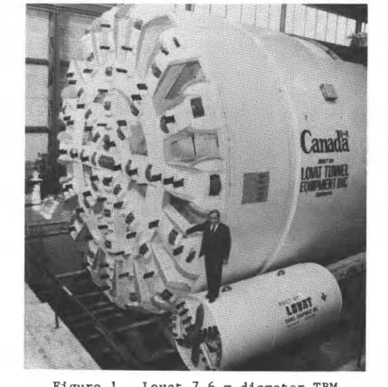
In March 1982, a contract was awarded by the federal government of Canada to Lovat Tunnel Equipment Inc. of Toronto, Ontario, for the construction of a 7.6 m diameter TBM to be used to drive haulageways for a new coal mine, the Donkin-Morien mine, near Sydney, Nova Scotia. The Donkin-Morien mine plan calls for the drivage of four parallel access tunnels up to 4 km in length
(Marsh et al., 1983). Because the coal deposit is situated offshore beneath the Atlantic Ocean, the specifications required that the TBM be designed for easy removal from the tunnels, which would blind-end at the intersection of the coal seam. This implied that the TBM would have to be both fully assembled and disassembled inside each
ERECTOR TRANSPORTER FOR EQUIPMENT 919 of the four tunnels. The first assembly was completed at a portal at the ground surface in 1983 (Palmer, Lovat and Marsh, 1985) but the remaining seven operations will have to be done underground.
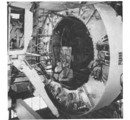
The Lovat TBM that was developed is a full-face, fully shielded design with electrohydraulic drive certified for use in a coal mine
(Figure 1). Because the TBM is fully shielded with all operating components mounted radially inside the shell (Figure 2), the design is unique, with several important operational advantages. The machine can be dismantled in a gassy atmosphere within a tunnel cut by itself and reassembled in a similar-sized chamber. In order to fully exploit this original design a piece of equipment was required which was capable of manoeuvring within a 7.6 m diameter tunnel while lifting and precisely positioning the components of the TBM. This requirement led to the development of the ET.
THE ERECTOR TRANSPORTER
The heaviest component of the TBM weighs 27 tonnes and its largest component measures 6 m in diameter and 0.5 m in thickness. The total weight of the TBM is in the order of 350 tonnes. A
machine capable of transporting, handling and accurately positioning such components inside a coal mine, within the confines of a 7.6 m diameter tunnel was not available, nor was there any company in Canada in a position to undertake, on its own, the design and development of such a unit.
920
1985 RETC PROCEEDINGS, VOLUME 2
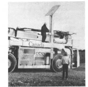
F i g u r e 3. E r e c t o r t r a n s p o r t e r l i f t i n g 30 t o n n e t e s t l o a d
A d e c i s i o n was made by t h e Canadian government t o s u p p o r t a n u n s o l i c i t e d p r o p o s a l from Beaver C o n s t r u c t i o n Group L i m i t e d of D o r v a l , Quebec, f o r t h e d e s i g n and c o n s t r u c t i o n of such a machine. The f i n a l d e s i g n and f a b r i c a t i o n of t h e ET was u n d e r way by J a n u a r y
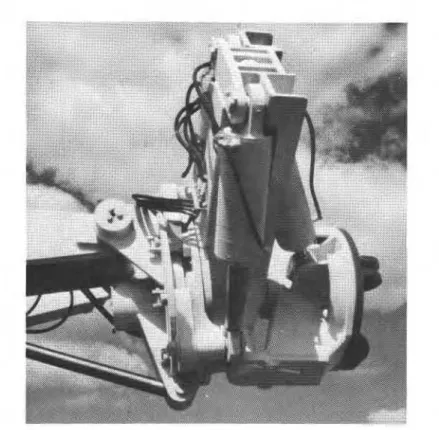
1983 w i t h a t a r g e t completion d a t e of September 1983. Although t h e ET i t s e l f c o u l d b e d e s i g n e d and b u i l t i n d e p e n d e n t l y of t h e TBM i t was c o n s i d e r e d e s s e n t i a l t o f a b r i c a t e t h e n e c e s s a r y i n t e r f a c e a d a p t o r s f o r t h e TBM's s u b a s s e m b l i e s b e f o r e t h e TBM was s h i p p e d t o t h e mine s i t e . The ET ( F i g u r e 3 ) i s i n e f f e c t a h i g h l y manoeuvrable t e l e s c o p i c boom mounted on a n e x p a n d a b l e , s e l f - p r o p e l l e d s t r a d d l e c a r r i e r . A key f e a t u r e of t h e ET i s t h e m a n i p u l a t i n g "head" ( F i g u r e 4 ) which i s mounted a t t h e end of t h e t e l e s c o p i c boom. The head can b e r o t a t e d w i t h h y d r a u l i c c o n t r o l s 210' i n a v e r t i c a l p l a n e ( t h e p l a n e of t h e photo, F i g u r e 4 ) , 105O i n a p e r p e n d i c u l a r v e r t i c a l p l a n e , and 95" i n a p e r p e n d i c u l a r h o r i z o n t a l p l a n e . It can be a c c u r a t e l y p o s i t i o n e d anywhere w i t h i n t h i s wide range.
PRINCIPAL PHYSICAL CHARACTERISTICS
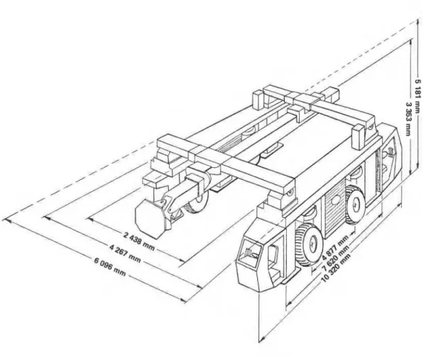
F i g u r e 5 i l l u s t r a t e s t h e major dimensions of t h e ET. Other p e r t i n e n t p h y s i c a l c h a r a c t e r i s t i c s a r e l i s t e d i n T a b l e 1. The
o v e r a l l w i d t h of t h e u n i t can b e expanded by 1829 mm and t h e o v e r a l l h e i g h t can b e expanded by 1828 mm, which p e r m i t s i t t o s t r a d d l e a n o b j e c t 4100 mm wide by 4100 mm h i g h . Each end frame i s
ERECTOR TRANSPORTER FOR EQUIPMENT
921
Figure 4. Manipulating head of main boom
TABLE 1
-
Principal Physical Characteristics Wheel baseSideframe length Vehicle length
Rear boom projection Minimum height, retracted Maximum height, expanded Roof jack extension Outrigger clearance Control cab width Combined grade peak Grade approachability Outrigger extension Front boom projection Telescopic boom stroke Min. width, closed Max. width, expanded Inside clearance, closed Inside clearance, expanded Inside turntng radius
Outside turning radius, closed Outside turning radius, expanded
1985 RETC PROCEEDINGS, VOLUME 2
Figure 5. Overall dimensions of erector transporter
is the ability of the unit to rotate about a circle of only 228 mm.
A feature not illustrated in Figure 5, but clearly shown in
Figure 6, is the roof jacks which can be extended 4572 mm and which
serve to stabilize the unit in the tunnel when the maximum load of
30 tonnes is lifted at the maximum extension of the main boom. For
surface operations, such as the trial dismantling of the TBM, counterweights are required to replace the function of the roof
jacks. These weights can be seen in Figure 3. Another feature not
well illustrated in Figure 5, but clearly shown in Figure 3, is the auxiliary service booms on either side of the main frame, which provide additional flexibility to the machine by safely handling
loads up to 1.2 tonnes.
MECHANICAL FEATURES
The ET has a 4-wheel hydrostatic drive powered by a 100 HP
Caterpillar 3304 diesel engine. The pair of wheels on each side is
ERECTOR TRANSPORTER FOR EQUIPMENT
923
Figure 6. Roof jack, partially extended
tight turning circle, allows the unit to be manoeuvred anywhere within the tunnel confines. In the event of a power pack failure the unit is equipped with a 40 HP auxiliary electric motor which can provide adequate hydraulic pressure to operate all the hydraulics except the propulsion. The hydraulic system operates on a 60140 waterloil emulsion. Fluid operating pressures are restricted to 21,000 kPa. In case of a malfunction, a series of pilot check valves ensure that all hydraulic cylinders remain in position until
the auxiliary power is activated.
There are two control cabs so that at all times the operator is in a safe working position with a clear view of the work area. Another safety feature is the provision of duplicate braking
systems, capable of bringing the unit to a safe stop from full speed down a 22% grade while carrying 30 tonnes.
VERIFICATION TESTS
A series of tests was undertaken in July and August 1983 at the Beaver site in Dorval and at a nearby quarry where various grades were available in order to verify that the unit met all
specifications. To test transportation capability, the machine was required to traverse a gradient of 22% at a speed of 1 km/hr while carrying a load of 30 tonnes. A major test of load handling
capability was to extend the main boom 3.65 m while lifting a load of 28.9 tonnes. For this test (Figure 3) the outriggers were down
924
1985 RETC PROCEEDINGS, VOLUME 2
and a counterweight was used in place of the roof jacks. The capability of the telescopic service booms to safely handle
1.2 tonnes while extended 5.5 m was also verified. All other
specifications were verified on site before the unit was transported to the Lovat plant in Toronto.
TESTS WITH 7.6 m TBM
Although the versatility of the manoeuvrable boom and head had been verified, it was still considered essential to demonstrate the machine's ability to dismantle and reassemble all the major
components of the TBM under shop conditions prior to its shipment to the mine site. Each major component of the TBM was removed and set on the shop floor as would be required in the tunnel and then placed back into position as required for the TBM's reassembly. Prior to each dismantling sequence it was necessary to manufacture
appropriate attachments to interface with the head of the ET and the respective TBM components. In spite of this necessary delay at each stage, all major components of the TBM were disassembled and loaded onto trucks for shipment within a period of only 19 days.
CERTIFICATION
During and after manufacture of the ET, various components were tested and the entire machine was inspected and tested as required to certify the unit as acceptable for use in a coal mine. Since this was a new design, certification was a major task. The fact that certification was obtained in the relatively short time period available (about nine months) attests to the excellent support given to this task by CANMET personnel.
APPLICATIONS
Testing to date under both shop and field conditions has proven conclusively that the ET is capable of performing its design
function of safely and speedily dismantling and assembling the 7.6 m diameter Lovat TBM within the confines of a similar-sized tunnel in a coal mine. The considerable expense and delay involved in the construction of underground erection chambers has therefore been eliminated. The versatility of the ET, however, is such that it could easily be used for other purposes, even though the prototype was designed specifically for handling the TBM components under the Donkin-Morien underground mine conditions. Subsequent versions of the ET can be reduced in size, powered by an electric-hydraulic power pack and otherwise modified as may be required for specific applications.
ERECTOR TRANSPORTER FOR EQUIPMENT
925
Suggested potential uses are very diverse, including surface mining operations such as loading, unloading, and transporting, use at surface construction projects, utilization as an extended
straddle carrier and even use within a ship's hold to handle
specialized bulk cargo. Any situation where low overhead clearance poses a problem and heavy lifts and precise handling of components is required, is a potential field of application for the ET.
ACKNOWLEDGEMENTS
Funding for this project, which was sponsored by the Department of Energy, Mines and Resources Canada (EMR), was provided by the Department of Supply and Services Canada and the Cape Breton
Development Corporation with the scientific support of EMR and the
National Research Council of Canada (NRCC). The project was closely
coordinated with the NRCC-sponsored development of the Lovat TBM and received excellent cooperation and support from Lovat Tunnel
Equipment Inc. Much of the original design was done by the late George Leskien, owner of GL Designs and Technical Services. Certification of the ET could not have been achieved without the exceptional cooperation of the staff of the Canadian Explosive Atmospheres Laboratory, EMRICANMET, in particular Mr. G. Lobay.
This paper is a contribution from the Division of Building
Research, National Research Council of Canada, and is published with the approval of the Director of the Division.
REFERENCES
Marsh, J.C., et al., 1983, "The Donkin-Morien Mine: Building the Mine of the Future," Presented at the 2nd Coal Operators
Conference, Sydney, Nova Scotia, October, 24 p.
Palmer, J.H.L., Lovat, R.P. and Marsh, J.C., 1985, "Performance of a
7.6 m Diameter Full-Face Tunnel Boring Machine Designed for a
Canadian Coal Mine," Fourth International Symposium, Tunnelling '85, Brighton, England, March.
T h i s p a p e r , w h i l e b e i n g d i s t r i b u t e d i n r e p r i n t form by t h e D i v i s i o n of B u i l d i n g R e s e a r c h , remains t h e c o p y r i g h t of t h e o r i g i n a l p u b l i s h e r . It s h o u l d n o t be r e p r o d u c e d i n whole o r i n p a r t w i t h o u t t h e p e r m i s s i o n of t h e p u b l i s h e r . A l i s t of a l l p u b l i c a t i o n s a v a i l a b l e from t h e D i v i s i o n may be o b t a i n e d by w r i t i n g t o t h e P u b l i c a t i o n s S e c t i o n , D i v i s i o n of B u i l d i n g R e s e a r c h , N a t i o n a l R e s e a r c h C o u n c i l of C a n a d a , O t t a w a , O n t a r i o , K I A OR6.
C e document est d i s t r i b u g s o u s forme de t i r 6 - 3 - p a r t par l a D i v i s i o n d e s r e c h e r c h e s e n b s t i m e n t . Les d r o i t s de r e p r o d u c t i o n s o n t t o u t e f o i s l a p r o p r i 6 t G de l l C d i t e u r o r i g i n a l . C e d o c u m e n t n e p e u t S t r e r e p r o d u i t en t o t a l i t 5 ou en p a r t i e s a n s l e consentement de 1 1 6 d i t e u r . Une l i s t e d e s p u b l i c a t i o n s d e l a D i v i s i o n p e u t Btre o b t e n u e en g c r i v a n t 3 l a S e c t i o n d e s p u b l i c a t i o n s , D i v i s i o n d e s r e c h e r c h e s e n b 3 t i m e n t , C o n s e i l n a t i o n a l d e r e c h e r c h e s Canada, Ottawa, O n t a r i o , K l A OR6.