HAL Id: cea-02492561
https://hal-cea.archives-ouvertes.fr/cea-02492561
Submitted on 27 Feb 2020HAL is a multi-disciplinary open access archive for the deposit and dissemination of sci-entific research documents, whether they are pub-lished or not. The documents may come from teaching and research institutions in France or abroad, or from public or private research centers.
L’archive ouverte pluridisciplinaire HAL, est destinée au dépôt et à la diffusion de documents scientifiques de niveau recherche, publiés ou non, émanant des établissements d’enseignement et de recherche français ou étrangers, des laboratoires publics ou privés.
subassemblies
V. Blanc, X. Jeanningros, P. Lamagnere, T. Helfer, T. Beck
To cite this version:
V. Blanc, X. Jeanningros, P. Lamagnere, T. Helfer, T. Beck. Characterization, simulation and improvement of spacer pads mechanical behaviour for sodium fast reactor fuel subassemblies. SMIRT 23 -23th International Conference on Structural Mechanics in Reactor Technology, Aug 2015, Manchester, United Kingdom. �cea-02492561�
Transactions, SMiRT-23
Manchester, United Kingdom - August 10-14, 2015 Division V: Modelling, Testing and Response Analysis
of Structures, Systems and Components
CHARACTERIZATION, SIMULATION AND IMPROVEMENT OF
SPACER PADS MECHANICAL BEHAVIOUR FOR SODIUM FAST
REACTOR FUEL SUBASSEMBLIES
Victor Blanc1, Xavier Jeanningros2, Pierre Lamagnere3, Thomas Helfer1, Thierry Beck1
1 CEA Cadarache, DEN/DEC/SESC, F-13108 Saint-Paul-lez-Durance, France 2
CEA Cadarache, DEN/DTN/STCP, F-13108 Saint-Paul-lez-Durance, France
3 CEA Cadarache, DEN/DER/SESI, F-13108 Saint-Paul-lez-Durance, France
ABSTRACT
CEA is currently working on a new prototype of Sodium cooled Fast Reactor, ASTRID, which must demonstrate strong safety level. Spacer pads, which are small bosses stamped through faces of the hexagonal duct, play a central role in this framework. Indeed, this component maintains proper spacing of fuel subassemblies. This spacing impact significantly the core reactivity, which could be decreasing due to a hypothetical core-flowering phenomenon then, be increasing during the compaction phase. Therefore, the stiffness of spacer pads needs to be well characterized and improved in order to prevent from unsafe reactivity insertion due to radial core compaction. For this purpose, a finite element model is used in order to reproduce the stamping process and obtain a representative geometry of the bosses. Moreover, the mechanical response of this model is successfully compared to experimental results of duct crushing at nominal temperature condition. Finally, this model is used in order to achieve an optimization of the design of the spacer pads for ASTRID subassemblies. This study shows that stiffness of this component can significantly be improved only by modifying its geometry.
INTRODUCTION
The spacer pads are small bosses stamped through faces of the hexagonal duct, just above the fissile zone of subassemblies. This component plays a central role in the mechanical equilibrium of a sodium fast reactor core, by ensuring a good clearance between subassemblies. This role is particularly important to prevent core compaction during normal operations and transient including unprotected events. Therefore, a high stiffness of this component is expected to eliminate any insertion of reactivity. The hexagonal duct thickness for ASTRID being thinner than for Superphenix (SPX1), for a close internal width, the stiffness of the spacer pads will also be reduced. Safety requirement for ASTRID leads us to improve performances of this component.
The first objective of this study is first to validate a finite element model in order to compute the mechanical behaviour of the spacer pads with accuracy. Indeed, this behaviour is used in core mechanical models as presented in Tsukimori and Negishi (2002), Lamagnere et al. (2015) and in Moussalam (2011). This spacer pads finite element model will as well be used in order to dimension the hexagonal duct. The second objective of this work is to optimize the shape of spacer pads in order to enhance their stiffness. In this purpose, a parametric study based on shape parameters of spacer pads is presented. The computations presented in this paper are performed using the LICOS fuel performance code, developed in the framework of the PLEIADES platform (see Plancq (2004)), which is based on the Cast3M finite element solver (see Cast3M (2015)). Mechanical behaviours describing hexagonal duct material has been implemented using the open-source MFront code generator (see MFront (2015)).
DEFINITIONS Spacer Pads Geometry
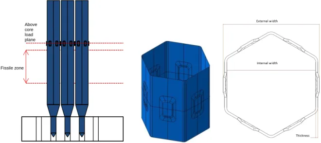
The spacer pads are realized by a stamping process on the six faces of the hexagonal duct. A grinding is then done on each pad in order to adjust width between two opposite pads, this width being the pitch of fuel subassemblies network in the reactor core, cf. Figure 1.
Figure 1: Position in a fuel subassembly and design of stamped spacer pads
Different shapes of stamped spacer pads have been used in the past, circular first for Phenix, then rectangular for SPX1. We choose here a set of parameters based on the SPX1 shape which is presented in Figure 2. Spacer pads are defined by the width L1, the stamping width L2, the height H1, the stamping height H2, the radii of the corners R1 and R2. The flat width L4 and the total width of the pads L2b are depending on the previous parameters. The pad depth p is given by the pitch between subassemblies. Likewise the flat width L3, the duct corner radius R3 and the thickness e are defined for all hexagonal ducts. Geometric data used for the model validation referring to the SPX1 and ASTRID ducts are given in Table 1.
Figure 2: Definition of the spacer pads shape parameters on a partial section of the hexagonal duct at the pads level (1/12) and above view of the pads.
Fissile zone Above core load plane L1/2 L2 L3/2 R3 L4 L2b/2 p e
23rd Conference on Structural Mechanics in Reactor Technology Manchester, United Kingdom - August 10-14, 2015 Division V Table 1: Shape data for Superphenix (SPX) and ASTRID
(mm) L1 L2 L3 L4 H1 H2 R1 R2 R3 e p
SPX 25 10 99.9 22.4 45 17.5 7 10 10.15 4.6 2.9
Astrid V2.0 25 10 97.4 21.4 45 17.5 7 10 9.55 3.6 1.6
Pads Stiffness Definition
Spacer pads may be submitted to various loading cases in the reactor core, depending on the subassembly position and the core deformation. The difficulty is that the relationship between a spacer pad deformation and the resulting force in one direction depends of the loadings on the other directions. Three load cases are described in Figure 3. If the material behaviour remains elastic and the geometry is perfect, a symmetrical matrix based on 4 coefficients connecting the six pads deformation and reaction can be written. This relation is not used in this study in order to simplify the comparison. We define here the stiffness by the ratio between a force applied on a pad and the variation of the distance from the pad to center of the section: K = Fi / ui . However, one must note that for some load cases the center of the section
can still move along loading direction, typically for the case 1F-3A. We will also use in the next section the variation of the distance between pads 1 and 4 to define the stiffness : u =(u1+u4).
Figure 3: Definition of load cases of the spacer pad section and of the stiffness associated. Material
Hexagonal duct for ASTRID is made of ferritic-martensitic steel called EM10 (9% Cr - 1% Mo), with a composition and metallurgic state close from the ASME Grade 91. An elasto-plastic law is used in order to compute crushing of the pads at 550 °C. This law is based on a three parameters approximation, Ramberg-Osgood (1943), described in 1D by Eq (1): 𝜎 = 𝐸(𝜀 − 𝜀𝑝) 𝑤𝑖𝑡ℎ 𝜀 𝑒𝑞𝑝= 𝐾 ( 𝜎𝑒𝑞 𝐸 ) 𝑛 (1)
Where E is the Young’s modulus, 𝜎 the stress, 𝜀 is the total strain, 𝜀𝑝 is the plastic strain, 𝜀
𝑒𝑞𝑝 and 𝜎𝑒𝑞 their Von Mises equivalent variables, and K and n being parameters.
Table 2: Material parameters used for the hexagonal duct at 550°C
T (°C) E (MPa) K () n ()
550 175000 2.72e32 12.709
FINITE ELEMENT MODEL VALIDATION Stamping Simulation
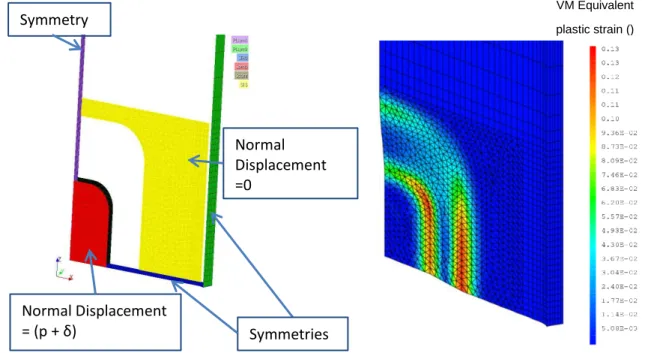
First step of the study is dedicated to the realization of a 3D finite element model. Feedback drove us to model a virgin hexagonal duct, and to simulate the stamping process in order to obtain a representative geometry. The duct is meshed with linear elements, pentahedrons and hexahedrons, with a mesh refinement in the deformed area, cf. Fig 2 and 4b. Using the symmetries, only a quarter of face of the hexagonal duct is necessary for this simulation. Surfaces of the mesh used to apply boundary conditions are shown in Figure 4a. A normal displacement (p + δ) is applied to the internal surface below the pad, δ being used to take into account the elastic part of the strain. The normal displacement of the yellow surface around the pad is set to zero. A plastic law identified at 20 °C is used for this simulation. A result of the simulation is shown on Figure 4b.
Figure 4: a - Description of boundary conditions used for the stamping process simulation; b – Example of field of equivalent plastic strain after stamping.
We observe on Figure 4b that the plastic strain is maximal in the corner of the pad and in the horizontal symmetry plane on the border of the deformed area. The maximum strain level is around 13 % for the considered geometry (SPX). The resulting deformed mesh is used in the following study for the stiffness pad’s assessment. Furthermore, this simulation will be used in the future in order to optimize the stamping process. Symmetries Symmetry Normal Displacement =0 Normal Displacement = (p + δ) VM Equivalent plastic strain ()
23rd Conference on Structural Mechanics in Reactor Technology Manchester, United Kingdom - August 10-14, 2015 Division V Titan Experiments
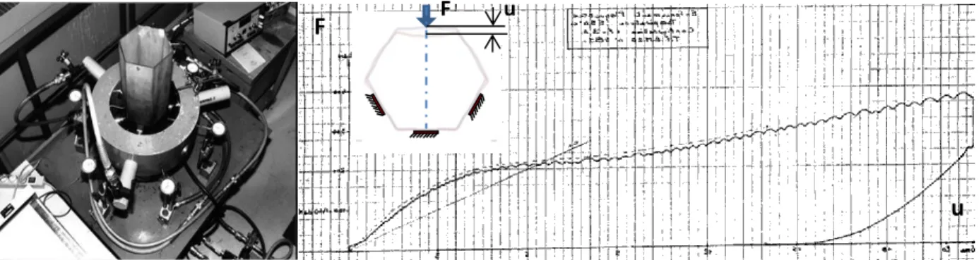
Crushing tests have been performed in the 90’s on hexagonal ducts in order to characterize the response of SPX subassemblies. The load case used for these tests is 1 force vs 3 bearing pads (called 1F3A in the follow) as described the Figure 3b. The displacement-force curve has been obtained at 550 °C, and is plotted on Figure 5b. We will consider this test as a reference in order to validate our FE model.
Figure 5: a - Titan test bed; b-Displacement-force curve for the 1F3A load case. Titan Simulation
We reproduce by symmetry the deformed mesh obtained by stamping in order to reproduce a quarter of hexagonal duct, which is necessary in order to describe 1F-3A test case (only two plane of symmetry, cf. Fig 3). An example of mesh used is showed on Figure 5a. Various sizes of mesh have been used in order to ensure the convergence of the response and to find the minimal size necessary to reproduce the experiments. Boundary condition on bearing pads is unilateral contact (normal displacement ≤0), and a unilateral contact condition is imposed as well between the superior pad and the moving jack. This condition is more precise than a uniform displacement condition which is stiffer and not representative of the contact. Test curve plotted Figure 5b is digitized and compared to simulation results on Figure 6b.
Figure 6: a- Finite Element mesh used for the 1F3A test case; b – Force-displacement curve comparison F u
F
We observe that the FE result is close to the experimental result, until a displacement around 4 millimeters which corresponds to the buckling of the pads. Mesh refinement shows that result for 85.000 nodes is a good compromise between computing time (2h/computation) and accuracy (1% difference with 175.000 nodes for the stiffness). The following of the study being dedicated to the elastic response of the pad (below 0.5 mm of displacement), we may consider that the FE model developed is representative of the spacer pad stiffness behaviour.
STIFFNESS OPTIMIZATION
We assume in the following parametric study that the clearance between subassemblies, and also the pad depth p is given. Likewise the flat width L3, the duct corner radius R3 and thickness E are defined by the hexagonal duct design.
First Parametric Study
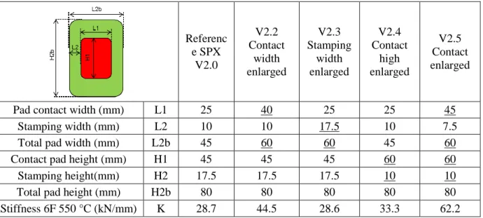
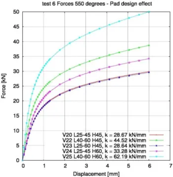
A first parametric study has been performed in order to find the influences of L1, L2 and H1, results are reported in Table 3. Five geometries have been generated, and computations of stamping and crushing have been performed at 550 °C for a 6F crushing test. Crushing curves are compared on Figure 7, and stiffnesses are reported on Table 3.
Table 3 : Initial design parameters values used for the spacer pads improvement and stiffness computed.
Referenc e SPX V2.0 V2.2 Contact width enlarged V2.3 Stamping width enlarged V2.4 Contact high enlarged V2.5 Contact enlarged
Pad contact width (mm) L1 25 40 25 25 45
Stamping width (mm) L2 10 10 17.5 10 7.5
Total pad width (mm) L2b 45 60 60 45 60
Contact pad height (mm) H1 45 45 45 60 60
Stamping height(mm) H2 17.5 17.5 17.5 10 10
Total pad height (mm) H2b 80 80 80 80 80
Stiffness 6F 550 °C (kN/mm) K 28.7 44.5 28.6 33.3 62.2
This first set of tests shows that:
- stamping width doesn’t influence stiffness (kV2.3 kV2.0)
- pads height and width have a major influence on the stiffness (kV2.0 < kV2.2 < kV2.4) - this combination of width and height enhancement improves the stiffness by a factor 2.
It should be very interesting to study local stresses at the same load level (Force), but computations are realized using imposed displacement of the pad. Nevertheless, these results show that strength of the spacer pads could be significantly and simply improved thanks to shape evolutions.
23rd Conference on Structural Mechanics in Reactor Technology Manchester, United Kingdom - August 10-14, 2015 Division V
Figure 7: Crushing curve of the hexagonal duct for 5 different pad shapes under 6 equal forces at 550 °C. Optimization Process
The ranges of the parameters have been defined by taking into account functional conditions and geometrical relationship briefly described as follows:
- Total width of flats is limited by the duct dimensions : L1 + 2.L2 + 2.L4 < L3 –R3 ~70 mm - Minimal width of flats surface between pad and duct corners is needed for stamping : L4 > 9 mm - Minimal stamping height because of handling : H2 > 10 mm
- Minimal stamping width because of maximal deformation rate (15 %): L2 > 5 mm - Maximal total height must be limited (influences subassembly height) : H2b < 100 mm - Minimal radius of the corner is necessary to limits local strains: R1 > 5 mm
- Maximal radius of the corner is necessary to prevent corner on symmetry axes: R1< min(L1/2, H1/2)
We made some choices in order to reduce cost computation and prevent from computation failure. Results shown that we must maximize L1, and that the stiffness increases when L2 is reduced, we set also a stamping width L2 to 5 millimeters. For the same reasons (maximizing H1, H2 minimal), H2 is set to 10 mm. R2 doesn’t influence the stiffness, his value is set to (R1+L2) in order to have a homogenous stress distribution. Then, variables of optimization are L1, H1 and R1. Range for L1 is limited by the flat width, H1 is limited by the total height. Simulations have shown that we must minimize R1 (cf. next section), we set his minimal value equal to SPX value in order to prevent high levels of plastic strains. Table 4 summarizes ranges for each shape parameter.
Table 4 : Design parameter values used for the optimization of the spacer pads stiffness. Reference SPX V2.0 V2.5 Contact surface enlarged Minimal value for optimization Maximal value for optimization
Pad contact width L1 25 40 40 60
Stamping width L2 10 10 5 5
Total pad width L2b 45 60 50 70
Contact pad height H1 45 60 60 80
Stamping height H2 17.5 10 10 10
Total pad height H2b 80 80 80 100
Radius of pad corner R1 7 7 7 12
Radius of matrix corner R2 10 10 12 17
Simulation Results
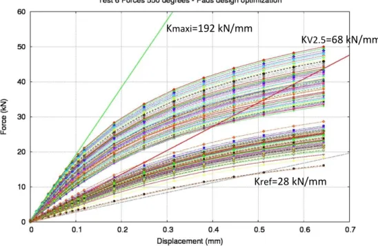
200 shapes have been generated in order to cover all the range of parameters. Stiffnesses are evaluated for each geometry on a 6F load case, for a displacement of the punch limited to 0.6 mm in order to reduce computation time. Crushing curves are plotted on Figure 8. One observes that the variations of parameters induce strong variation of the mechanical behaviour of pads. Some computations have failed, the bundle of curves is also not continuous.
Figure 8: Crushing curves of the hexagonal duct for 200 shapes of pads Kref=28 kN/mm
KV2.5=68 kN/mm Kmaxi=192 kN/mm
23rd Conference on Structural Mechanics in Reactor Technology Manchester, United Kingdom - August 10-14, 2015 Division V
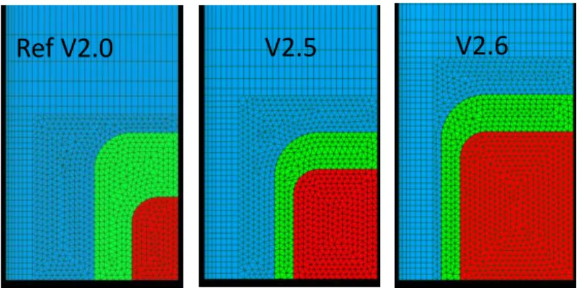
Stiffnesses are computed for each shape using the elastic part of the response. The maximum value for the stiffness is obtained for extremal parameters: L1 maximal (60 mm), H1 maximal (80 mm), R1 minimal (7 mm), which is called V2.6. The ratio between reference and maximal stiffness is around 1 for 7. Shapes associated to the 3 stiffness values mentioned on the Figure 8 are compared on Figure 9. We observe that the contact pad surface of this V2.6 is larger than initial version V2.0 by a ratio of 4.
Figure 9: Comparison of spacer pad shapes giving the lower (V2.0, K=28 kN/mm), intermediate (V2.5, K=68 kN/mm)) and the higher stiffness (V2.6, K=192kN/mm).
CONCLUSION
In this study, a finite element model has been developed, by taking into account the forming process of the structure. This finite element model has been used in order to compare simulation to results of crushing tests realized on a hexagonal duct in temperature. Results of comparisons validate the model in a good agreement.
Then, we have shown by using this model that the shape of spacer pads could be optimized in order to enhance their stiffness. Simulations results showed that a ratio of 7 could be reached.
Those results have to be validated by an experimental campaign of stamping process and crushing tests, which are currently in progress at CEA.
However, optimal choice for the pads will have to be done by taking into account all the operating phases. Indeed, stiffness is in fact limited by its impact on the maximal subassemblies extraction force as it is presented in Lamagnere et al. (2015), and the width of the pads may be limited by the influence of the clearance between subassemblies on the natural convection flow.
NOMENCLATURE
ASTRID : Advanced Sodium Technology Reactor for Industrial Demonstration SPX : Superphenix
E : Young’s modulus,
𝜎 : Stress tensor, 𝜎𝑒𝑞 : Equivalent stress 𝜀 : Total strain tensor, 𝜀𝑝 : Plastic strain tensor, 𝜀𝑒𝑞𝑝 : Equivalent plastic strain
K : Plastic law parameter.
n : Plastic law parameter.
REFERENCES
Cast3M (2015), Cast3M computation code by Finite Element, http://www-cast3M.cea.fr.
Lamagnere, P., Dardour, S., Dos Santos, R., Freiermuth, A., Marqués, M., Pérot, N. and Schmidt, N. (2015), « Multi-objective optimization of subassemblies design towards static mechanical equilibrium of sodium cooled fast reactor core », Transactions, SMIRT-23, Manchester, Div X Paper #456.
MFront (2015), http://tfel.sourceforge.net
Moussalam, N., Bosco, B., Beils, S. (2011). “ Industrial model for the dynamic behaviour of liquid metal fast breeder reactor (LMFBR) core,” Transactions, SMIRT 21,New Delhi, Div. V Paper 81.
Plancq (2004), D. Plancq, G. Thouvenin, J.-M. Ricaud, C. Struzik, T. Helfer, F. Bentejac, P. Thévenin, R. Masson, “PLEIADES : a unified environment for multi-dimensional fuel performance modeling”,
in: International meeting on LWR fuel performance, Florida, 2004.
Ramberg, W. and Osgood, W. (1943) “Description of stress-strain curve by three arameters,”Technical
Notes N° 902, National Advisory Comittee for Aeronautics, 07/1943.
Tsukimori, K. and Negishi, H. (2002). “Development of ‘Pad Element’ for detailed core deformation analyses and its verification,” Nuclear Engineering and Design, UK 213 141-156.