Plasma induced energy deposition and radiation transport
effects in ion beam heated plane metal targets and
analytic solutions of the non-linear radiation
conduction equation
By K. A. LONG
Institute de G6nie Atomique, Departement de Physique, Ecole Polytechnique Fe'de'rale de Lausanne CH-1015 Lausanne, Switzerland
AND
N. A. TAHIR
Institute for Neutron Physics and Reactor Engineering, Nuclear Research Centre, Postfach 3640, 75 Karlsruhe 1, Federal Republic of Germany
(Received 22 July 1985: in revised form 4 November 1985)
The effects of microscopic energy deposition in hot, dense plasmas and radiation transport in plasmas, on the interaction of ion beams with plane metal targets are investigated in this paper. In order to do this we analyze the plasma dynamics of ablatively accelerated plane metal foils. The physical analysis of these results is achieved by the derivation of solutions of the non-linear radiation conduction equation with boundary temperatures which increase in time. We illustrate, by means of numerical simulations, how range shortening due to plasma effects such as increased energy loss to excited electrons and an increased effective charge due to a reduction in the recombination rate, may be compensated for by radiation transport. The effect of radiation transport and detailed microscopic energy deposition on ion beam implo-sions, including hydrodynamic instability, is discussed.
1. Introduction
In ion beam driven implosions of inertial fusion targets (Clauser 1975; Bangeter & Meeker 1976; Long & Tahir 1981; 1982a; Tamba et al. 1983; Tahir & Long 1982b; 1983a), it is important to investigate the effects of many different physical processes in order to be able to judge the feasibility of this fusion scheme. In previous calculations we have not considered the detailed plasma effects on the ion energy deposition, and the effect of radiation transport on the implosion has not been considered (Long & Tahir 1981; Tahir & Long 1982b, c; Tahir & Long 1982d; Long & Tahir 1982a; Tahir & Long 1983a; Tahir & Long 1982a). One of the most important problems in inertial fusion is whether or not the implosion can be made hydrodynamically stable. Both energy deposition and radiation transport have a significant effect on the stability of the implosion of spherical targets. In order to investigate these problems we have carried out theoretical and numerical investigations of the interaction of an ion beam with plane metal targets (Long & Tahir 1984b; 1986b; Tahir & Long 1986b). This work then complements that done on the implosion of spherical targets (Long & Tahir 1985c, 1986a; Tahir & Long; 1986a; b),
The transfer or excitation of bound electrons into free electron states causes range shortening because free electrons scatter ions more efficiently than electrons in bound states (Long, Moritz & Tahir 1983b; Nardi, Peleg & Zinamon 1978; Mehlhorn, 1981). 0263-0346/86/0402-0287S05.00
Furthermore, because electron capture occurs more readily from bound electron states than from free electron states, the effective charge on an ion in a plasma is higher than in a cold material (Nardi & Zinamon 1982). This contributes to additional range shortening, especially as the energy loss is proportional to the square of the effective charge. The reduction in the range increases the mass of material which has to be accelerated to produce ignition. For a reasonable power level this makes it impossible to obtain ignition. Thus the volume of heated material has to be increased and this can be done either by increasing the ion energy or by radiation transport (Long & Tahir 1985c; 1986a; b). In this paper we illustrate the second process in plane metal targets. Radiation transport is the dominant conduction process in such plasmas, being much greater than electron conduction above a temperature of 100 electron volts. However as Hora (Hora 1983; Hora & Ghatak 1985) has pointed out electron conduction is further reduced to the ion conduction value by double layer effects at the ablation front. For the purpose of model calculations, it is useful to have available expressions for the distance of travel of radiation waves or Marshak waves (Tahir & Long 1984a; b; Long, Tahir & Pomraning 1983a; Long & Tahir 1984a). In the case of pellet calculations the temperature in the deposition region near the end of the range is an increasing function of time, due to the fact that the power of the ion beam rises with time. Therefore solutions of the non-linear radiation equation are required for which the driving temperature is an increasing function of time. Therefore we have solved, both analytically and numerically, the non-linear radiation conduction equation for a boundary driving temperature which depends on an arbitrary power law of time and an exponential function of time. In order to do this we have first used a self-similar transformation to reduce the problem to the solution of a non-linear ordinary differential equation. However it is important to note that self similar transformations do not of themselves solve such a problem. Here we employ an interesting iterative technique, which is an example of a contraction mapping (Kolmorgorov & Fomin 1961) which has its fixed point as the solution. This method allows one, not only to solve accurately for the speed of the non-linear wave, but also for the shape of the wave.
The organization of this paper is as follows. In § 2 we discuss some aspects of the non-linear radiation conduction equation used to carry out the numerical simulations of
LOW DENSITY
HEATED REGION TAMPER
PAYLOAD
FUEL (DT)
\ RADIATION SHIELD (Pb) RANGE
(High density) SHORTENING
FIGURE 1. Ion beam driven tamped target in its working phase showing range shortening and its compensation by ablation due to radiation transport.
radiation transport. This equation is solved analytically in § 3, where we also discuss applications to inertial fusion pellet implosions. In § 4 we briefly present the model used to calculate the energy deposition profiles, and the interpolation scheme used to couple the microscopic ion energy deposition into the hydrodynamic code MEDUSA-KAL (Long & Tahir 1981; Tahir & Long 1983c), which is a development of the Rutherford Laboratory version of the MEDUSA code (Evans & Bell 1981; Christian-sen, Ashby & Roberts 1974). In § 5 we present results of numerical simulations of plane metal targets which include the plasma effects on the microscopic energy deposition and radiation transport. These results illustrate how radiation transport can compensate for range shortening in hot and dense plasmas, which is an essential aspect of inertial fusion target calculations (Long & Tahir 1985c; d; 1986a; b). In § 6 we then investigate the effect of energy deposition and radiation transport on the growth of the Rayleigh-Taylor instability. In § 7 we present our conclusions, that we have derived from this work.
2. The non-linear radiation conduction equation
In assessing the qualitative importance and quantitative effect of radiation and electron conduction in inertial confinement fusion pellets, one useful model is that of the non-linear heat conduction equation (Zel'dovich & Raizer 1965), which has been used previously in a simple form (Tahir & Long 1982a; Long & Tahir 1982a) to assess the importance of radiation preheat in target calculations (Long & Tahir 1981; Tahir & Long 1982b; c; Tahir & Long 1982d; Long & Tahir 1982a; Tahir & Long 1983a; Badger et al. 1981).
This equation can be derived using the energy balance equation,
p dt
where p is the density, Cp is the specific heat at constant pressure (henceforth replaced
by Q, the specific heat at constant volume), T is the temperature, t is the time, S is the heat flux and W is a source term. The heat flux transported by radiation is given by
(2)
where / is the Rosseland mean free path, c is the velocity of light, Up is total energy in
the radiation field at temperature T, and a is the Stefan Boltzmann constant. In many cases one has,
l = ATm (4)
where m = 3-5 for Bremsstrahlung in a fully ionized plasma and 1-5 to 2-5 in multiply ionized gases.
Using (1) and (3) one obtains,
dTidt = v. (x vr) (5)
X = K/pCv (6)
where K is the thermal conductivity, and
If one uses (4),
K = -^-Tn = BT" n = m + 3 (9)
x = KlpCv=-^T" = bTn (10)
The non-linear heat conduction equation then takes the form,
b = (16aA)/3pQ (11) We now review some of the assumptions under which this equation can be expected to be valid.
(a) The energy in the radiation field is much less than that in the material. 4aT4
«l(Z + \)NkT + I(T) (12) c
where Z(T) is the number of ionized electrons at temperature T, N is the number of atoms/unit volume and /(T) is the ionization energy/unit volume for Z ionized electrons/atom
(b) The specific heat is temperature independent. In the case of partially ionized plasmas the specific heat is not constant, so we relax this condition below. In this case the specific heat is allowed to have a power law temperature dependence. (c) The density should be independent of time.
(d) An opacity of the form K = KopyT~m, m>0. In cases considered here the
density dependence is not considered.
(e) Various boundary conditions can be considered, see below. The assumptions necessary to assure the validity of the diffusion equation should also be considered. In general the radiation field should be isotropic, and the radiation energy density at each point in the medium should be close to equilibrium. This means also that the radiation mean free path should be small compared to other lengths in the problem for instance the size of the heated region, and that the radiation density should not change much over distances of the radiation mean free path.
In the case of plasma formed by multiply ionized atoms as already stated the second condition needs to be relaxed. In shielding against the deleterious effects of radiation for instance in ICF pellets one uses high Z materials such as gold or lead because here the Rosseland mean free path is short (Tahir & Long 1983b; Tahir & Long 1984a). Temperatures of the order of 10-100 KeV must be reached before these materials become fully ionized. In the case of multiply but partially ionized plasmas the energy per unit volume E can be written as,
E = paTk+i (13)
T = (E/pa)v(k+i) (14)
so (11) transforms to, 3 £ / 3 / = 6, v. ( £- -v £ ) (15)
b> =
Thus the transformation of the solution of (11), T - T(x, y, z, t) into the solution E = E(x, y, z, t) of (15) for any specific problem can be accomplished by replacing the constants b and n by b' and n'.
In order to solve (11) or (15) one needs to know the boundary conditions. For instance the case of an instantaneous heat source released at say x = 0, can be solved exactly (Long, Tahir & Pomraning 1983a; Long & Tahir 1984a; b;c; Barenblatt 1952; Petschek, Williamson & Wooten 1960; Marshak 1958; Pomraning 1967; 1968). In problems connected with ICF pellets one needs to be able to solve problems where the temperature on the boundary is a given function of time. For instance in simulations without radiation transport the temperature was found to increase exponentially in time at the interface between the hot cavity region and the pusher region. When radiation is included a strong radiation wave will be launched into the pusher. This already happens to a certain extent in the sense that an electron conduction wave moves into the pusher however this is much more slowly moving than the radiation wave because electron conduction is «• T* whereas radiation conduction is proportional to T% ~ T$. It is also restricted by the double layer effect. Self similar type solutions for (11) and (15) exist at least for the following cases in which the boundary temperature is specified as a function of time.
(i) 7 ( 0 , 0 = To (18)
(ii) T(0,t) = Tot"/tpo (19)
(iii) r ( 0 , 0 = T0e2&l (20)
For all these cases there exist similarity type transformations which reduce (11) and (15) to first order differential equations. For case (i),
For case (iii), T = Toe™f{z) (22)
z = x e- ( m + 3)&, ( 2 3)
where, n = m + 3. Similarity transformations are a sophisticated form of dimensional analysis. In general the solution of such problems as posed above yields a Marshak wave, which is a non linear thermal wave moving into the medium. The wave form is such that the temperature is nearly constant for most of the space x < xw where xw is
the position of the wave front. Near to the wave front the temperature decreases very sharply to zero, at x =xw. One very useful quantity to know is xw and its dependence
on time xw{t). Reasonably accurate answers can be obtained by simple dimensional
analysis and physical intuition.
If one considers problem (5), using simple dimensional analysis,
dT/dt = Tolt, BTIdx ~ T0/xw (24)
where xw{t) is the position of the wave front at time t. Then from (11),
(25) (26)
where Q, is the specific heat/g. Thus
(28) A more accurate estimation can be obtained as follows, using a physical argument. The heat flux (energy/unit time) is used to heat up material ahead of the wave to a temperature To . . .
^V4o pCvT0dxJdt (29)
3 c
In a more general case of temperature dependent specific heat Q, To can be replaced by E(T0) (energy/g)
E{T0)=\°Cv{T)dT (30)
Replacing V7*4 by T%lxw one obtains,
Integrating one obtains,
If
A (32)
Other methods have been used, in particular a method of successive approximations, which converges to numerical results, and this method yields the formula,
(34) where one must assume a constant specific heat, E(T0) = QTo, and t]0 is a factor close
to one. The expressions (33) and (34) agree to within a factor of 1-15 when rjo= 1.
3. Self similar transformation and solution for a boundary temperature which varies as a power of the time
We first consider the self-similar transformation for boundary temperature T(0, t) = To(tp/to), case ii, §2, where p>0. Thus this includes the constant boundary temperature case for which p - 0. Let us write (11) as,
^ ^ ( 3 5 )
dt (n + 1) Using n = m + 3,
3T b d2
dt (m + 4) 3x2 By inspection of the other two cases we assume that,
(36)
and, Then, dt <g wy ' "fgaz" at (40) Further, 4)' dx2 since z is linear in JC. dz t" m+43x2 (m
Comparison of (40) and (43) shows that in order to have a valid, similarity transform, 0 9 - l ) = p ( m + 4) + 2o- (44)
..fc^te+fl (45)
( 4 6 )
For p = 0, a = ~2 which is case (i). For large p,
(47) where it is of interest to point out that in the exponential case the factor -(m + 3)/2 reappears as the exponent of the exponential.
Using (37) and (38) in (35) one gets with use of (45), (40) and (43),
as the resulting 1st order differential equation for case (ii), and (i) is given for p = 0. The boundary conditions for this problem are,
= r
0£ o</<=° (49)
'0
(2) r(oo,0 = 0 for r > 0 . (50) (3) T(x,0) = 0 for x>0 (51)
The similarity solution is,
() (52) 'o \ «o
(1) implies /(0) = 1, and (2) implies /(°°) = 0. Thus (3) is also seen to be satisfied. Equation (48) is still not quite in the form which we desire. Let us make the transformation, F r o m, 3 7 ) , w eget, or , , N((m + 3)/2)p
« -
D^ ( T )
(55) where,[
91, ym+3-1-1r^T-—1 (56)
(m + 4) J v 'the similarity variable £ is now dimensionless. The ordinary differential equation to be solved is now,
^ ^Q
(57)(58) Let us take m + 4 = n + l = «. The boundary conditions that insure that a solution to (57) is a true radiation wave have been shown by Marshak (1958) to be,
(a) 7 = 1,1 = 0 (59) dT"
(b) At some point £0, T = — - = 0. (60)
d§
The first follows from the fact that ahead of the front of the wave the temperature is zero, and the second condition is the condition which determines the front of the wave, where T(^o) = 0, and the flux = 0, simultaneously (Petschek, Williamson & Wooten
1960).
Equation (57) is solved by the successive approximation method due originally to Picard. A first integration of (57) yields
dT" h rh
= f
where
4>(p) = (p(m+3) + l) (62) 0(0) = 1 (63) Taking £t = If, and £2 = |0, we get, and using the boundary condition at £0
dT" fSo fl0 dT"
- + q>\p)<i ~z~d$ (64)
Further,
? dT"
— d§' (65)
\%)=-\ -jgdl' (66) The scheme of iteration rests on (64) and (66), and consists of the following.
(a) Choose a temperature distribution which obeys the boundary conditions, but which is of unspecified length £0- Here we choose r(£) = 0 ( |o - §) which is 1
when £ < £0 a nd z e r o when § > £0
-(b) Obtain (dT"/d^) (which is proportional to the flux) by inserting the above approximation in the R.H.S. of (64).
(c) Obtain r * ( | ) by inserting (</7"7dg) from (b) in (66). (d) Determine £0 from the condition,
T"(0) = 1 (67) (e) Take the nth root of (c) as the function in (a).
In practice this procedure converges to the numerical solution and our conjecture is that it can be shown to be a contraction mapping in a suitable metric space. This would then insure the uniqueness and existence of the solution obtained by this method.
We now derive the second approximation here for the first approximation we take,
= 0, § > £0 (68) Then from (64) dTn~\w
jl
=djl
2^^)<KP)£o (69)
Then using (66) ^( 2 ) |5° (70) (71) ( | ) ( | ) (72) Using T"(0) - 1 , 1 = §o(p + 4>(P)) (73) i l ( 7 4 ) (75) This is the first approximation to %0. We now takeThen
'-) (76)
l/n
(77) Integrating (64) by parts, we obtain,
dT"
(78)
•^(p))/°nr)rfr (79)
Using T(^)(2) from (77), and y = (1 - (?/|0)), one obtains,
+ 2 p £ i - -_y(2"+»/« . _ _ ^ (80)
Using T"(0) = 1,
(ft + 1) (2g + 1) 1 ]
"
This yields the constant temperature solution for p = 0. We assume in what follows that this is always the case, i.e. that the constant temperature solution for ^0 can be
multiplied by [1 + p(m + 4)]"1 to obtain the f case.
In the constant temperature case the series of approximations to g"0 are,
a"=i (82)
The exact value of %o(m) where n =m + 4 is given in (Petschek et ai, 1960) and is calculated by numerical methods. For m - 3,
= M065
whereas £0 = 1-1199, so there is very good agreement even for this solution. In this
where
£(sp~
(85)
and §0 is given in (81). For the constant temperature case
T*\x, t) = r o( | § ( ^ ^ (1 - &ZoY*+m{l " (1 " §/|o)/(2n + I))))1'" (87)
where
f-Dyj (88)
-' (8 9 )
In order to determine the time dependence of the wave front xw(t), we use (67)
f.-^f
(90)
in the second order approximation. The exact solution is obtained by multiplying by a factor very close to one. For m = 3-0,
r2 / , \ _ _ T
6
\ v / (921
.
(()=N
PgPf^
(93)
(94) in the second approximation, where I = ATl.
(95)
in the exact solution. For the general tp case,
For m = 3,
I
2 ^
where l = ATl. In the exponential case,
T(x,t) = T0e2&t at x = 0 (99)
T = 0 at f = -oo for x>0. (100) The similarity transform is,
2&tf{z) (101)
Substituting this in (36), one obtains,
as the equation corresponding to (41). Putting (m + 4) a I or m + 4 a = Exe-<m+v&' (105) Then d2 riT(P) (107) (108) This is the same equation as in the f case, when one takes (57) p = 1, and $(1) — 1 instead of (p{\), i.e. replaces m + 4 by m + 3 . Therefore using the same method as above, (m + 3)^(1 - §/|0) (111) (HI) and | | g | ( 2 ) = (» + l)(2n + l) _ 1 _ ( n 3 ) e2(""+3)ar'-l) (114) jc^ln = (116)
For m = 3,
*»-(0=\/—^~i VTT^"l
e-
1] (
1 1 7>
^ ( u
=
2-089 ' 12 " <*This reduces to the constant temperature solution when a—>0, and thus the factor 2-18 from this analysis has been replaced by 2-089. It has been mentioned elsewhere (Long
& Tahir 1982a; 1985d; 1986a; Tahir & Long 1983a; 1984a; 1984b; 1985a; 1986a; 1986b) that it is very important to stop radiation preheat reaching the fuel. Modified HIBALL targets have been discussed which contain a high-Z radiation shield around the fuel. Detailed numerical simulations and theoretical interpretations of these results are reported in the above references. In these calculations the temperature in the absorption region, at the end of the ion range reaches between 300 and 400 eV.
Since, at these temperatures, the radiation wave ionizes the material into which it travels, the specific heat is temperature dependent. The energy in the plasma at a given temperature is composed of the translation energy of the ions and electrons together with the ionization energy, and the excitation energy of the atomic levels. The number of free electrons is however not constant but increases with temperature due to ionization. Neglect of such effects by the use of (34) with a constant specific heat typical of a cold material would lead to unrealistically large penetration depths. However use of (33) with a realistic expression for E(T0) gives more reasonable results
which are still however quite large when available opacities for high Z materials are used (Pritzke 1975; 1982).
The energy in a classical plasma can be written as (Geiger, Hornberg & Schramm 1968)
i (119) where Z(T) is the number of ionized electrons and I(T) is the ionization energy at temperature T. In dense plasmas a better approximation is given by the Thomas Fermi model.
However use of (36) for the energy gives reasonable agreement with Los Alamos Tables (Bennett et al. 1978), at least at solid densities.
For solid lead, using data in Pritzke (1982)
Z(T) = 6-6 x lO-2r°-4 (120)
where T is in degrees Kelvin. Also detailed calculations show that the terms in (119) are approximately equal. Therefore we use,
E(T) = 3 . (6-6 x i o -2r0 4 + l)kBNT (121)
where kB is Boltzmann's constant, and N is the number of atoms/gm.
N = ^ (122) where NA is Avagadro's number and n is the atomic weight. Therefore the energy/gm
is,
E(T) = 3 . (6-6 x io~2T°-4 + \)RTIpL (123) where R = NAkB is the gas constant.
Neglecting the factor 1, because Z » 1, one can see that the factor k of (13) is 0-4. Now (34) can be written as,
xw = VI \bTfr (124)
where
^ (125) This is also correct for (15) in the form,
xw = Vtib'EZt (126) Using , Vk + l (127) n-k ( 1 2 9 )
One can show that (129) is valid providing one uses
E(T) = paTk+1 (130)
and therefore the energy for lead in the form of (121), or in general a similar expression of the form (129) with different values of a and k. Therefore for lead one has,
_ / l U *
Xw
~\2 3(6-6 x i o
where the factor 1 has been restored. From the physical derivation of (130) it is clear that this is valid.
At 800 eV and at solid density (11-2 g/cc) for lead, xw = 387 /im for t = 10 ns, where
the temperature To at the boundary remains constant.
For gold at solid density (19-7 g/cc),
Z(T) = 6-1 x l 0 -2r ° -4 (132) and in this case xw = 220 fim for To = 800 eV and t = 10 ns. For To = 400 eV for gold xw is
strongly reduced to 48 jum for t = 10 ns, as one would expect. The opacities used for these calculations are taken from (Pritzke 1982), and do not include many effects that need to be included such as bound-bound transitions. However in Nardi and Zinamon (1978; 1982) it was calculated that at 1 keV in solid density gold, the inclusion of bound-bound transitions reduced the Rosseland m.f.p. by a factor 3. Assuming that this factor holds at lower temperatures and is also true for lead, the values xw calculated
above can all be reduced by a factor 1-7, giving values corresponding to the conditions given above of 227, 130 and 28 fim respectively. Radiation shielding layers of the order (initially) of ~ 20 ^m will be needed in order to shield the fuel from radiation preheat. These results were obtained with the inclusion of the temperature dependence of the specific heat of high Z materials which become partially ionized (Z ~ 40 at 800 eV) at temperatures of the order of a few hundred eV.
ablation front returns to roughly the same place. It is obviously essential to have very accurate calculations of the opacities of high Z materials in order to make pellet calculations more realistic, because of the strength of radiation conduction, which at these temperatures dominates electron conduction; radiation conduction going as T? to
T^ while electron conduction increases at r i Analytic solutions to the radiation
conduction equations for given boundary conditions can be used to check the accuracy and numerical method of radiation codes in this limiting case.
In actual calculations (Long & Tahir 1981; Long, Moritz & Tahir 1983b; Long & Tahir 1985a; 1986b; 1985c) the range shortening is very large, whereby the hot range ends just after the inner boundary of the tamper. As the material heats up the range shortens very quickly as the temperature rises to 100 eV. As it rises further to 250 —350 eV, a Marshak wave starts to propagate back towards the fuel. The power level has to be adjusted in pellet calculations (Long & Tahir 1985b; c; 1986a) so that the radiation wave can move fast enough and far enough to bring the ablation front back to a point where the mass of material accelerated to the necessary 3 x 107 cm/sec is small enough, or in other words the same as it would have been if there had been no range shortening (Long & Tahir 1985a; Tahir & Long 1985a).
4. The microscopic theory of the ion energy deposition in hot and dense plasmas and its interpolation in fast running hydrodynamic codes
In ion beam fusion calculations one needs to be able to calculate the ion energy loss in plasmas with densities lying in the range 10p^ to p.,/1000, where ps is the solid
density, and temperatures lying in the range between zero and 1 KeV. The Gorgon energy deposition code (Long, Moritz & Tahir 1983b) can accomplish this task for any ion in any plasma. An ion travelling through a plasma loses energy mainly to electrons through a series of small angle collisions in which the energy transfer is also small (Deutsch, Maynard & Minoo 1983). Since the mass of an ion is much larger than an electron, a fast moving ion, whose velocity is much larger than the thermal electron velocity or the average bound electron velocity, is deflected through very small angles and to a very good approximation can be considered to travel in a straight line.
Most models used to calculate the ion energy deposition (Mehlhorn 1981; Nardi, Peleg & Zinamon 1978; Beynon 1982; Long & Tahir 1981; Long, Moritz & Tahir 1983b) in plasmas, do so by calculating the energy loss to bound and free electrons separately. The contribution of the bound electrons to the stopping power is calculated using the Bethe theory (Bethe 1936), taking into account the difference in the characteristic excitation energies between a neutral atom and an ion in a plasma via the finite temperature Thomas-Fermi model (Latter 1955). The contribution of the free electrons to the stopping power in the Gorgon code, is calculated using the dielectric function for a plasma within the random phase approximation, and by the employment of linear response theory. Therefore for bound electrons,
)
where / is the Bethe parameter which is calculated within the Thomas-Fermi theory, and m is the electron mass, /3 = v/c, where c is the velocity of light and cop is the
plasma frequency. For free electrons,
where p is the density, E is the ion energy, X is the distance travelled by the ion, e is the electric charge, Zeff is the effective charge on the ion, k is the wave number,
H = cos 6, E is the dielectric function and V is the ion velocity. The effective charge is calculated as for cold materials, with an empirical allowance for the increased effective charge due to plasma effects.
The data calculated by the above method must be coupled into MEDUSA-KAL (Christiansen, Ashby & Roberts 1974; Evans & Bell 1981; Long & Tahir 1981; 1986a; Tahir & Long 1983c), the hydrodynamic code used in these calculations.
In order to couple a computing efficient and flexible routine into MEDUSA we decided to use an analytic interpolation method (Long & Tahir 1984c; 1985c; 1986a). The analytic functions chosen to do this job were derived from theoretical considera-tions. Theory can provide simple and reasonably accurate formulae at low and high energies and an interpolation method was used in between. The method used is an extended version of the one used to fit the cold data (Anderson & Ziegler 1977). This method has the advantage that it can simultaneously fit dEI(JR)ldR, dR(E)ldE, E{R) and R(E), where R is the range and E is the ion energy. The parameters used all have a physical interpretation. Thus as the energy deposition calculations become more sophisticated because of the inclusion of different physical processes, changes in the data can be relatively easily incorporated in the full calculation, as all parameters of the model appear in the Namelist input of MEDUSA. The effect of changes in energy deposition on pellet performance can also be easily investigated.
For reactor size targets, either light ions or heavy ions, the range of energies of interest is limited to about 3 orders of magnitude. For protons for instance the energy ranges from 10 MeV down to zero, but energies below 10 KeV are not of much interest because the small amount of energy possessed by an ion with this energy can not affect the calculation, since the range is so small compared to the total range and to the cell size in the calculation. Similarly for heavy ions, i.e. for Bismuth ions of initial energy 10 GeV, energies of interest are only in the range down to 1 MeV. At low energies, the LSS theory gives a V £ dependence for dE/dR, while at very high energies dEldR behaves as E~x. In general it is found that the range-energy curve R{E) has two linear parts showing power law behaviour in each of the low and high energy regimes.
Thus the scheme for fitting is as follows,
)M) (135) W (136) Then,
> ' w ( i ) " -
s
'
1 +
^ - ^
(137)
and,() ta
(
n\-Yi E^~a^ I O\~Y2 ]?(l-a2)forms o f / , ( r ) and/2(T) can be different in different temperatures ranges and a, y, etc.
can depend on p and T. For heavy ions of energy above 3 GeV, it was found that the range could be fitted by the following formula,
(140) where E is the energy, T is the temperature, p is the density, EQ, TO and ps are
reference values, and AR is the range shortening at To, and Ro is the cold range at EQ,
and ps.
In order to see approximately how such a relation arises one can start form a simplied high energy expression given by Mehlhorn (Mehlhorn et al. 1983)
_tdE _\43Z2lZ2AUZ2-Z2) Z± 1
dX htAi L Zsi Zs£ J
where Zu Zi are the charges on the beam and target ion, At and A2 are the atomic
mass of the beam and target ions, E is the ion energy, Z^ is the average degree of ionization, A{ is the Coulomb logarithm for free electrons and Ab = [(Zz — Z2)/Z2]118A&
where Ab is the Coulomb logarithm modified for partial ionization. Now Zj can be
written approximately as Zi = AT6 where <5 = 0-4168. Assuming the logarithm factors remain roughly constant.
Ap c CA T6 / A \
where C is a constant, and
-idE C P J p ( ^ = 0) = -ln(Af t) (143) dX E dE' (144) dE' AT
ln(A
6) + —
-(145) The factor in front of the brackets is the range at T = 0, and the similarity between (145) and (140) is demonstrated. The factors Eo, ps and To are simply scaling factorscorresponding to a given set of units. Using a more complicated theory changes the exponents but not the form of the expression. The density dependence is weak, i.e. y is greater than zero but close to zero, but the changes in density are large. This type of formula, (140) is only valid as long as the low energy part of the stopping power where dEldR decreases, is not important, i.e. for Te<545E(MEV)/A where Te is the
electron temperature. At low energies the specific energy loss has roughly the LSS form, and varies as VE, SO this is roughly the form of £,(£)
= QE"' (146) where
The scheme described above has been used to fit the data from the GORGON code for 10 GeV Bismuth ions incident on lead. In target simulations the ions pass through the lead and have about 3 GeV energy left when they enter the lithium or lithium-lead (depending on the target design). The above scheme has also been used to fit the data for lithium and lithium-lead. One should note that in lead one only needs to know the high energy part of the curve whereas in lithium-lead the low energy part is equally important. It is this region in which the shocks are generated and ablation or thermal pressure implodes the payload. However the low energy data is not very accurate at present, and the effective charge at low energies in plasmas has to be calculated, so only an approximate method has been used at low energies for the time being. In general (for heavy ions) the energy deposition has three regions as a function of temperature (for heavy ions).
The first is below 10~20eV where the free electrons are degenerate, in the second the range shortens rapidly from 20 eV to 200 eV and in the third the range is more slowly varying, and may even lengthen a little.
Each of these temperature regions can be fitted separately in order to obtain the necessary accuracy ~10%. Energy deposition calculations are not as accurate as this at the present time, although this kind of accuracy will be required.
5. Numerical simulations of plasma induced microscopic ion energy deposition and radiation transport effects in plane metal targets
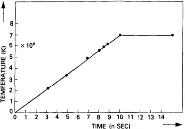
Corresponding to the analytic solutions derived above, we have carried out numerical simulations of non-linear radiation waves with the MEDUSA-KAL code. Firstly we have carried out simulations in which a temperature pulse of the form shown in figure 2 is applied to the left hand boundary of a plane gold target (Long & Tahir 1984a). The temperature of the pulse rises linearly from zero to 7 x 10⁶ K over a period of ten nanoseconds and then remains constant. In this case we do not consider any hydrodynamic motion. In figure 3 we show the resulting non-linear radiation wave as it propagates through the plasma which it creates. The amplitude of the wave builds up as the boundary temperature rises, and the velocity of the wave increases. After 10 nsec the wave propogates as if the boundary temperature had been constant the
0 1 2 3 4 5 6 7 8 9 10 11 12 13 14 TIME (n SEC) •
FIGURE 2. Boundary temperature versus time as used in the numerical simulations of Marshak wave propagation.
35 -THOMAS FERMI E.O.S. and THOMAS FERMI IONIZATION 10 20 30 NUMBER OF CELLS DISTANCE (ARBITRARY UNITS)
40 50
FIGURE 3. Radiation wave propagation for the boundary temperature profile shown in figure 2.
10 20 30
NUMBER OF CELLS DISTANCE (ARBITRARY UNITS)
50
FIGURE 4. Ionization wave due to radiation wave propagation using the boundary temperature profile shown in figure 2.
whole time. In this case the amplitude remains the same and the velocity of the wave decreases with the passage of time. Such waves are observed in target calculations (Long & Tahir 1985b; c; 1986a), where the power of the beam is rising. Even when the power is constant the temperature rises because the energy fed into the plasma is increasing in time. In tamped targets or in cases where the ion range is long there is little hydrodynamic motion over times less than the range divided by the velocity of sound, which is the disassembly time. As the wave propagates, it ionizes the material turning it into a plasma. This ionization wave is shown in figure 4, and it has a similar shape to the temperature wave.
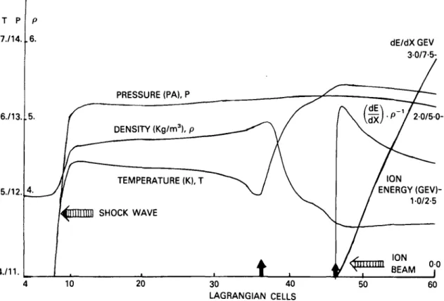
In order to illustrate this process further, we have carried out numerical simulations on plane metal targets, which have a thickness greater than the range of the ions which make up the beam (Tahir & Long 1986b; Long & Tahir 1986b). In these simulations we have included hydrodynamic motion, thermal ionization using a Thomas-Fermi model, radiation transport and the plasma effects on the energy deposition using the methods described in the previous section. The energy deposition curves are shown in (Long & Tahir 1982b; 1985c, 1986a). The bismuth ions in the beam have an initial energy of 8 GeV, and the beam has a power of 600 TW/cm2. In figure 5 we show what happens at 3-33 nsec when a plane lead target is irradiated by such a beam. The temperature has already risen to above 100 eV. A shock wave has been launched into the material of the plane target beyond the end of the ion beam range, which heats and ionizes the lead, turning it into a partially ionized plasma. In the meantime, due to the plasma heating and ionization of the lead by the ion beam, the ion beam range has shortened by a considerable amount. The energy deposition profile is now considerably
T P 7./14. 6./13. 5./12. 4./11. P .6. .5. _4. _/
I
PRESSURE (PA), Pc
~~
/ DENSITY (Kg/m3), p M TEMPERATURE (K), TUjllllllllll SHOCK WAVE
• I 1
t , i
dE/dX GEV 30/7-5-r\ /dE\ _ , // V l d x )
p/ 2-0/5-0
/ I O N /ENERGY (GEV)-/ 10(GEV)-/2-5 /X ION/ f ™ BEAM °j°
10 20 30 40 LAGRANGIAN CELLS 50 60FIGURE 5. Numerical simulation of a plane lead target irradiated by a 600 TW/cm2 beam of bismuth ions with an initial energy of 8 GeV, at 3-3 nsec.
different from the cold profile (Long, Moritz & Tahir 1983b; Long & Tahir 1985c; 1986a). The actual energy deposition profile and the ion energy are shown in figure 5. One can just start to detect the formation of a Marshak wave coming from the end of the present range. One should of course note that, in this case in contradiction to that above, the 'boundary' from which the wave is launched is moving to the right. In figure 6 we show the process after 5-58 nsec. The range has further decreased and the Marshak wave has propagated further to the left. By this time the shock wave has reached the left hand boundary of the plane target and a rarefraction wave has started to run back into the target from the left hand boundary. The range shortening is due to the decrease in the density and to the rise in the temperature. The expansion to the right behaves like a driven expansion (Long & Tahir 1986b), in which the temperature rises until it is saturated due to radiation losses. From this time on the range shortening is due solely to the decrease in the density. Although the range is still shortening it is not doing it as quickly as before. The Marshak wave has now built up into the standard shape. The energy deposition and the ion energy are again shown in the diagram. The state of the plane target is again shown at 11-26 nsec in figure 7. The Marshak wave is now fully developed and ablation of the lead is now taking place as the wave moves to the left. Figure 8 shows the state of the plane target at 17-5 nsec, in which the whole process has attained a steady state. These results show that over the time of a pellet implosion, which is of the order of 10 nsec, radiation transport can compensate more or less exactly for the range shortening. The compensation can be controlled by the temperature, which is in turn controlled by the power level. Thus if the range shortening should be larger due to say a larger effective charge then this will represent
T P P 775./14. 674713. 573712. 4./2./11. — ' DENSITY (Kg/nrv ^ PRESSURE —~> TEMPERATURE (K), T ( P A ) , P ' / . COLD \ RANGE JK6 MARSHAK WAVE
V
—
_
/
/
ION BEAM — . / I O N ENERGY(GEV) 20 30 40 50 LAGRANGIAN CELLS 60 70T P 7. 5. 6. 4. ID - J
S3
w 5. 3. 4. 2. T P P 7./13./5. 6./12./4. 5./11./3. 4./10./2. """"DENSITY (Kg/m3), p \ TEMPERATURE (K), T /t
/MARSHA / WAVE1
<
\ . DEPOSITED / I O N ENERGY / ^ (GEV) y / . ION • >^ <^zzza BEAM si i 20 60 50 40 30 20 10 0 0 30 40 50 LAGRANGIAN CELLSFIGURE 7. As in figure 5 at 11-26 nsec.
60 70 175 nsec, TEMPERATURE (K), T 9. GEV 20 0. 00 40 50 LAGRANGIAN CELLS 60 70
no problem when it comes to obtaining ignition. Of course the wave moves much faster in materials with lower opacity than lead. By mixing lead with for instance lithium, one can also adjust the distance the waves move in a given time. This can prevent radiation entering the fuel on the one hand and allow the wave to move far enough to compensate for range shortening on the other, for a given power level.
6. Hydrodynamic stability
The stability or instability of implosions of inertial fusion targets is one of the most important problems which confronts inertial fusion (Rayleigh 1883; Taylor 1950; Chandrasekhar 1961; McCrory, Morse & Taggart 1977; Mikaelian 1982; Long & Tahir 1981; 1985c; 1986a; Tahir & Long 1982b; 1986a; b). In this section we make some comments on what can be learned about this problem from the plane target simulations reported on in this paper, and we discuss some empirical theories of the Rayleigh-Taylor instability, and the effects which energy deposition and radiation transport have on this instability.
The acceleration of the cold heavy (denser) part of the plane target by the hot lighter (less dense) part is a highly non-equilibrium process. Systems near to equilibrium which are in the linear regime, where forces and fluxes are related linearly, relax towards equilibrium and thereby maximize their entropy and their disorder. Systems which are far from equilibrium can, particularly when they are non-linear systems, spontaneously form ordered structures. This happens for instance when a shock wave traverses a boundary. In the case of the Rayleigh-Taylor instability the denser fluid tries to flow into the less dense fluid (Sharp 1984). This process is started by any fluctuations on the surface, which can be regular or random. Most of the research on the Rayleigh-Taylor instability has been carried out starting with sinusoidal pertuba-tions of the surface. Regular fluctuapertuba-tions or disturbances in plane or spherical geometry could be caused by overlapping beams. Random fluctuations or perturbations could be caused by range straggling of the ions in the ion beam. The instability seems to have many features in common with other non-equilibrium processes. Out of fluctuations ordered structures of spikes and bubbles grow continuously. The spikes increase in number, as new spikes appear in between each pair of spikes, and they thus multiply in a frequency doubling manner (Feigenbaum 1983). Later small bubbles amalgamate into larger bubbles, to form even more ordered structures (Youngs 1984). Still later the spikes and bubbles break up to form a chaotic turbulent layer. However turbulent motion is not random, but involves the coordinated motion of all the molecules in the system. These processes can only be observed and simulated properly in three dimensions. In the linear regime effects such as radiation ablation stabilization and density gradient effects have been analyzed (Long & Tahir 1985c; 1986a; Tahir & Long 1985a; 1986a; b). Non-linear growth rates are smaller than linear growth rates, so a linear analysis is a worst case analysis. The simulations carried out on plane targets show clearly that the processes in ion beam fusion are not as simple as the usual analysis of the idealized Rayleigh-Taylor instability, where two fluids of different density are accelerated by external means together. In ion beam fusion the material to the left of the end of the ion beam range is at first accelerated by the shock wave which also produces an instability, and then by the pressure of the heated material to the right of the end of the range. The material to the left is also compressed, so the low density material appears to be pushing the higher density material. If the range remained fixed, this situation would be the steady state situation. However as the range shortens, a density gradient is established and the pushing region is spread out. Then as
the Marshak or radiation wave forms and moves to the left it causes ablation and eats away some or all of the growth in the instability. Use of radiation to help drive the implosion by ablation thus reduces the growth rate of the instability. It does this because it reduces the thickness of the shell. We now discuss an empirical theory of the Rayleigh-Taylor instability in its turbulent stage (Read 1984; Youngs 1984). This model uses a one dimensional model of the mixing process of the denser and lighter fluids. It considers that the process can be described by the equations of two phase flow. The result is that the distance hx, that the turbulent mixed region penetrates into
the dense shell, is given by
hi = pA.g.t2 (147)
where A is the Attwood number equal to (p2 — Pi)/(P2 + Pi), where p2 is the density
of the compressed shell and pj is the density of the heated region. Consider a shell of width A/? and radius R. Then the aspect ratio A = R/&R. In this theory and from experiment /3 = ^ .
For an implosion, the acceleration g = Rlt2c, where tc is the implosion time.
Therefore,
$ (148) If the mixing region spreads through the shell into the fuel, then high Z material will mix into the fuel and the burn will be degraded due to emission of Bremsstrahlung radiation. Thus if the aspect ratio is greater than 14, it appears that the implosion will fail. For R = 0-3 cm, this means that AR must be greater than 200 ^m. The advantage of using radiation to drive the implosion is now apparent. Radiation transport allows one to start with a thicker shell, because radiation ablation eats into the shell in order to drive the ablation and the implosion. This would occur in a purely radiation driven target, and it also happens in the ion beam implosions described in (Long & Tahir 1985c; 1986a; Tahir & Long; 1985a; 1986a; b), and in the plane target simulations illustrated in this paper, because of the range shortening and its compensation by radiation transport. Radiation transport also smooths out the implosion due to the large lateral conduction.
If the distance xw which the radiation wave moves is greater than hu then the mixing
region does not interfere with the implosion. It essentially remains behind the ablation front. If the power increases linearly with time, then the distance xw is proportional to
fi If the power rises at t2, then xw is proportional to t2. This corresponds to the
dependence of hx on time. The radiation wave can then be made to travel faster by
increasing the temperature. Thus by ramping the power fast enough as a function of time, the instability problem can be bypassed. If radiation is generated within a low opacity shell, inside a tamper, then only a few (2) beams are needed.
Formula (147) looks surprisingly simple, and it has the form of an equation that comes from a dimensional analysis of the problem. This is probably the case, as once the system becomes turbulent or chaotic it has forgotten its initial conditions and the only length in the problem is g. t2. At this stage the motion is self-similar. A theory of bubble amalgamation comes to the same numerical result as the above theory, with A = 20 at its most pessimistic.
7. Conclusions
In this paper it has been shown that the effects of both detailed microscopic ion energy deposition in plasmas and radiation transport have a substantial influence on
the interaction of ion beams with plane and spherical metal targets. The ion range in plasmas is substantially reduced over the cold range and due to this effect the volume of the heated region decreases during irradiation both in plane and spherical targets. In spherical target implosions this leads to a loss of ignition. On the other hand at sufficiently high temperatures, radiation transport becomes much larger than electron conduction and can substantially extend the volume of the heated region in both plane and spherical targets. In cylindrical targets the effects are the same provided that the beam is perpendicular to the axis. If the beam is parallel to the axis then range shortening can lead either to a loss of heating in part of the target, or to increased power deposition depending on whether the cold range is less than or slightly greater than the length of the target or whether it is substantially greater than the length of the cylinder. Similarly in sub range plane targets range shortening leads to increased power deposition. In these type of targets radiation transport and radiation losses essentially limit the attainable maximum target temperature. Since the temperature tends to be constant anyway in driven expansions, the role of radiation transport is limited to transporting energy to the surfaces or the optically thin regions, where it is radiated away, providing the temperature reaches a high enough value. The maximum temperature is attained when the radiation losses, which are always less than the black body value, are equal to the energy in the ion beam coming in per unit time and per unit area. The numerical simulations presented in this paper have demonstrated these effects in plane targets. In order to analyze these effects analytically deep inside the target where in effect the plasma is tamped by the rest of the plasma over times less than the disassembly time, we have shown that the concept of Marshak waves is useful especially if one uses Lagrangian coordinates. Since the temperature increases with time in this region, solutions are required for which the boundary temperature is a rising function of time. We have demonstrated an iterative technique for solving the ordinary non-linear differential equation resulting from the self similar transformations of the non-linear radiation conduction equation. We have presented accurate solutions for the speed of the non-linear radiation waves and for the shape of these waves. We have also discussed the effect that radiation transport and energy deposition have on the hydrodynamic stability of the acceleration or implosion. Range shortening produces density gradients which can ameliorate the stability of an implosion. We have also shown that even in the turbulent phase of the Rayleigh-Taylor instability, radiation transport can make the implosion stable. At high enough driving tempera-tures, the radiation wave must travel faster than the rate at which the instability grows, especially if the power and hence the temperature are increasing with time. The radiation then drives the implosion or acceleration by ablation. Then providing one starts with a thick enough pusher shell, the implosion will be successful, as long as the radiation ablates away enough material so that the necessary terminal velocity of 3 x 10⁷ is obtained.
REFERENCES
ANDERSON, H. & ZIEGLER, J. 1977 Hydrogen stopping power and ranges in all elements, Pergamon Press, New York.
BADGER, B. et al. 1981 HIBALL, A conceptual heavy ion beam driven fusion reactor design, KfK-3202.
BANGETER, R. & MEEKER, D. 1976 Ion beam inertial fusion target design, UCRL-78474. BARANBLATT, G. I. 1952 Prikl. Mat. i. Mekh. 16, 67.
BENNETT, B. I. et al. 1978 LA-7130.
BEYNON, T. D. 1982 Phil. Trans. Roy. Soc. London, A300, 613.
CHANDRASEKHAR, S. 1961 Hydrodynamic and hydromagnetic stability, Oxford university press, England.
CLAUSER, M. J. 1975 Phys. Rev. Lett. 35, 848.
CHRISTIANSEN, J. P., ASHBY, D. & ROBERTS. K. V. 1974 Comp. Phys. Comm. 7, 271. DEUTSCH, C , MAYNARD, G. & MINOO, H. 1983 7. Phys. (Paris), C8, 67.
EVANS, R. G. & BELL, A. 1981 private communication.
FEIGENBAUM, M. J. 1983, Physica, 7D, 16.
GEIGER, W., HORNBERG, H. & SCHRAMM, K. H. 1968 Springer tracts in modern physics, Volume 46, Springer Verlag, New York.
HORA, H. 1983 Laser and Particle Beams, 1, 231.
HORA, H. & GHATAK, A. K. 1985 Phys. Rev. A, 31, 3473.
KOLMOGOROV, A. N. & FOMIN, S. V. 1961 Elements of the theory of functions and functional
analysis, Graylock Press, Rochester N.Y.
LATTER, R. 1955 Phys. Rev. 99, 1854.
LONG, K. A. & TAHIR, N. A. 1981 Energy deposition of ions in materials and numerical
simulations of compression, ignition and burn of ion beam inertial confinement fusion pellets,
KfK-3232.
LONG, K. A. & TAHIR, N. A. 1982a Phys. Lett. 91A, 451.
LONG, K. A. & TAHIR, N. A. 1982b GS/-82-6, 54.
LONG, K. A. & TAHIR, N. A. & POMRANING, G. C. 1983a GS/-83-2, 39.
LONG, K. A., MORTIZ, N. & TAHIR, N. A. 1983b GORGON, a computer code for the
calculation of the energy loss and stopping power in cold materials and hot dense plasmas,
KfK-3608.
LONG, K. A. & TAHIR, N. A. 1984a GS/-84-5, 51.
LONG, K. A. & TAHIR, N. A. 1984b GS/-84-5, 71.
LONG, K. A. & TAHIR, N. A. 1984c G5/-84-5, 73.
LONG, K. A. & TAHIR, N. A. 1985a G5/-85-21, 61.
LONG, K. A. & TAHIR, N. A. 1985b G5/-85-21, 49.
LONG, K. A. & TAHIR, N. A. 1985c Proceedings of the international conference on Atomic
Physics in ion beam fusion, September, 1984, Rutherford Laboratory Report, to be
published.
LONG, K. A. & TAHIR, N. A. 1986a Fusion Technology, submitted for publication.
LONG, K. A. & TAHIR, N. A. 1986b Phys. Fluids, 29, 275.
MARSHAK, R. E. 1958 Phys. Fluids, 1, 24.
MEHLHORN, T. A. 1981 /. Appl. Phys. 52, 6522.
MEHLHORN, T. A., PEEK, J. M , MCGUIRE, E. J., OLSEN, J. N. & YOUNG, F. 1983 / . Phys. (Paris), C8, 39.
MCGRORY, R., MORSE, R. & TAGGART, K. A. 1977 Nucl. Sci. Eng. 64, 163. MIKAELIAN, K. O. 1982 Phys. Rev. A, 26A, 2140.
NARDI, E., PELEG, E. & ZINAMON, Z. 1978 Phys. Fluids, 21, 574. NARDI, E. & ZINAMON, Z. 1982 Phys. Rev. Lett. 49, 1251.
PETSCHEK, A. G., WILLIAMSON, R. E. & WOOTEN, J. K. 1960 LAMS-2421.
POMRANING, G. C. 1967 /. Appl. Phys. 38, 3845. POMRANING, G. C. 1968 /. Appl. Phys. 39, 1479.
PRITZKE, R. A. 1975 Multigroup cross sections for thermal radiation in a uranium plasma,
Doctoral thesis, Technische Hochschule, Zurich.
PRITZKE, R. A. 1982 Thermal radiation multigroup absorption cross sections for inertial fusion
target materials, Laboratory report IM-3-18, S.I.N., Switzerland. RAYLEIGH, LORD, 1983 Proc. London Math. Soc. 14, 170.
READ, K. I. 1984 Physica, 12D, 45. SHARP, D. H. 1984 Physica, 12D, 3.
TAMBA, M., NAGATA, N., KAWATA, S. & Niu, K. 1983 Laser & Particle Beams, 2, 121. TAHIR, N. A. & LONG, K. A. 1982a GS/-82-6, 59.
TAHIR, N. A. & LONG, K. A. 1982b AtomKernenergie, 40, 157.
TAHIR, N. A. & LONG, K. A. 1982c Phys, Lett. 90A, 242.
TAHIR, N. A. & LONG, K. A. 1982d GSI-82-6, 53.
TAHIR, N. A. & LONG, K. A. 1983a Nucl. Fusion, 23, 887.
TAHIR, N. A. & LONG, K. A. 1983b OS/-83-2, 38.
TAHIR, N. A. & LONG, K. A. 1983c MEDUSA-KA, KfK-3454.
TAHIR, N. A. & LONG, K. A. 1984a Laser & Particle Beams, 2, 371.
TAHIR, N. A. & LONG, K. A. 1984b G5/-84-5, 52.
TAHIR, N. A. & LONG, K. A. 1985a G5/-85-21, 62.
TAHIR, N. A. & LONG, K. A. 1986a AtomKernenergie, to be published.
TAHIR, N. A. & LONG, K. A. 1986b Phys. Fluids, to be published. TAYLOR, G. 1950 Proc. Roy. Soc. 201A, 192.
YOUNGS, D. L. 1984 Physica 12D, 32.
ZEL'DOVICH, YA. B. & RAIZER, YU. P. 1965 The physics of shock waves and high temperature