HAL Id: tel-00474041
https://tel.archives-ouvertes.fr/tel-00474041v2
Submitted on 16 Mar 2011
HAL is a multi-disciplinary open access archive for the deposit and dissemination of sci-entific research documents, whether they are pub-lished or not. The documents may come from teaching and research institutions in France or abroad, or from public or private research centers.
L’archive ouverte pluridisciplinaire HAL, est destinée au dépôt et à la diffusion de documents scientifiques de niveau recherche, publiés ou non, émanant des établissements d’enseignement et de recherche français ou étrangers, des laboratoires publics ou privés.
generator including energy storage system with
super-capacitors and hydrogen technologies for
microgrid application
Tao Zhou
To cite this version:
Tao Zhou. Control and energy management of a hybrid active wing generator including energy storage system with super-capacitors and hydrogen technologies for microgrid application. Other. Ecole Centrale de Lille, 2009. English. �NNT : 2009ECLI0010�. �tel-00474041v2�
ECOLE CENTRALE DE LILLE
THESE
présentée en vue d’obtenir le grade deDOCTEUR
en
Spécialité : Génie Electrique par
Tao ZHOU
DOCTORAT DELIVRE PAR L’ECOLE CENTRALE DE LILLE
Titre de la thèse:
Commande et Supervision Energétique d’un Générateur Hybride Actif Eolien incluant du Stockage sous forme d’Hydrogène et des Super-Condensateurs
pour l’Intégration dans le Système Electrique d’un Micro Réseau
Soutenue le 30 Juin 2009 devant le jury d’examen :
Président Geneviève DAUPHIN-TANGUY, professeur, Ecole Centrale de Lille, LAGIS
Rapporteur Bernard DAVAT, Professeur, ENSEM de Nancy, GREEN
Rapporteur Daniel HISSEL, Professeur, Université de Franche-Comté, FEMTO-FCLAB
Membre Yongdong LI, Professeur, Université de Tsinghua, Beijing, Chine
Membre Stéphane LECOEUCHE, Professeur, Ecole des Mines de Douai
Membre Gille NOTTON, Maître de Conférences (HDR), Université de Corse, LSPE
Membre Frédéric COLAS Docteur-Ingénieur de recherche, ENSAM ParisTech, L2EP
Directeur de thèse Bruno FRANCOIS, Maître de Conférences (HDR) Ecole Centrale de Lille, L2EP
Thèse préparée dans le Laboratoire L2EP à l’Ecole Centrale de Lille Ecole Doctorale SPI 072
Control and Energy Management of a Hybrid Active Wind Generator
including Energy Storage System with Super-capacitors and
Hydrogen technologies for Microgrid Application
Tao ZHOU
Ph.D dissertation
Laboratoire d’Electrotechnique et d’Electronique de Puissance de Lille (L2EP) ECOLE CENTRALE DE LILLE, FRANCE
Preface
The PhD work, which is presented in this thesis, has been done at the “Laboratoire d'Electrotechnique et d'Electronique de Puissance de Lille” (L2EP), from September 2006 to July 2009. This work has been carried out as a part of a research project “ANR– SUPERENER”, at Ecole Centrale de Lille with the support of the French National Research Agency (ANR) and the China Scholarship Council (CSC).
Acknowledgements
This dissertation is not only a result of my own dedication and perseverance, but is largely a credit to the patient and helpful people that I have worked with and to the supporting and understanding people that I have lived with over these past three years. I would like to take this opportunity to express my gratitude to everyone who contributed to this work.
My sincere thanks go to my supervisor, Dr. Bruno FRANCOIS, for his confidence in me throughout this project and for his valuable guidance during the study.
I would like to thank members of the jury, Prof. Bernard DAVAT, Prof. Daniel HISSEL, Prof. Yongdong LI, Prof. Geneviève DAUPHIN-TANGUY, Prof. Stéphane LECOEUCHE, Gille NOTTON and Frédéric COLAS, for their valuable discussions and insightful comments during the writing of the manuscript.
I am equally indebted to Prof. Stephane LECOEUCHE and his colleagues (Mohamed el hadi LEBBAL, Didier JUGE-HUBERT and Gabriel HOUSSAYE) in the Department of Informatics and Control Systems of the Ecole des Mines de Douai for their generous cooperation and helpful discussion when I worked on the electrolyzer system in their laboratory. Working with them during that period has been a very enriching experience. I am also very grateful to Prof. Alain BOUSCAYROL and his colleagues (Anne-Laure ALLEGRE, CHEN Keyu, Walter LHOMME and Christian DEMIAN) in the control team of the L2EP for their constructive suggestions and continuous help during my work on the fuel cell system in their laboratory.
Many thanks go also to Xavier CIMETIERE, Simon THOMY, Christophe RYMEK and Hicham FAKHAM for their enormous help on implementation of the experimental test bench. I would like also to thank my colleagues in the Grid Network Team (Omar BOUHALI, LI Peng, LU Di, PENG Ling, Gauthier DELILLE, ZHANG He, Amir AHMIDI) and my colleagues in the L2EP (TRAN Tuan Vu, Arnaud VIDET, Jean LEBESNERAIS, Fouzia MOUSSOUNI, David MARIN, Francois GRUSON, Souleymane BERTHE, Xavier MARGUERON, Guillaume PARENT) for their infinite friendship and encouraging supports. Finally, I am infinitely grateful to all my friends and my families for their moral support, to my parents for their continuous encouragement, and especially to my wife LU Yao for being supportive and understanding during these three years, which are also the most difficult period for her study.
Explore everything around you,
penetrate to the furthest limits of human knowledge,
and always you will come up with something inexplicable in the end.
It is called life.
Albert Schweitzer
Contents
Preface ... iii
Acknowledgements... iii
Contents... v
Nomenclature of Symbols ... xiii
Introduction ... 3
Chapter I Context and Methodologies ... 6
I.1 Renewable energy sources and distributed generation ... 6
I.1.1 Renewable energy sources ... 6
I.1.2 Distributed generation ... 8
I.1.3 Smart grid... 9
I.1.4 Microgrid... 10
I.1.5 Hybrid power system... 12
I.2 Hydrogen as alternative energy carrier to electricity... 12
I.2.1 Hydrogen market... 12
I.2.2 Hydrogen-electric economy ... 13
I.2.3 Hydrogen as storage for electricity... 14
I.3 Integration of renewable energy based generators into a microgrid... 15
I.3.1 General framework of the microgrid operation... 15
I.3.2 Problems of renewable energy sources ... 15
I.3.3 Concept of active generator... 16
I.4 Presentation of the studied active generator ... 17
I.4.1 Technologies of wind generators ... 17
I.4.2 Classification of energy storage systems... 19
1.4.3 Long-term storage system through hydrogen technologies ... 20
1.4.4 Fast-dynamic storage unit by super-capacitors... 20
I.4.5 Structure of the studied hybrid power system ... 21
I.5 Objectives and methodologies of the PhD thesis... 22
I.5.1 Objectives... 22
I.5.2 Tools... 22
I.5.3 Methods... 24
I.5.4 Thesis layout ... 25
Chapter II Wind Energy Conversion System ... 28
II.1 Study of a wind energy conversion system ... 28
II.1.1 Presentation... 28
II.1.2 Modeling of the wind energy conversion system ... 29
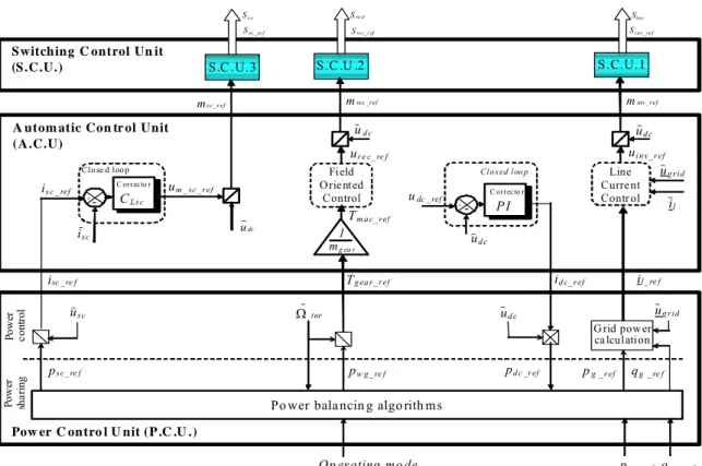
II.1.3 Hierarchical control structure... 32
II.1.4 Automatic control unit ... 33
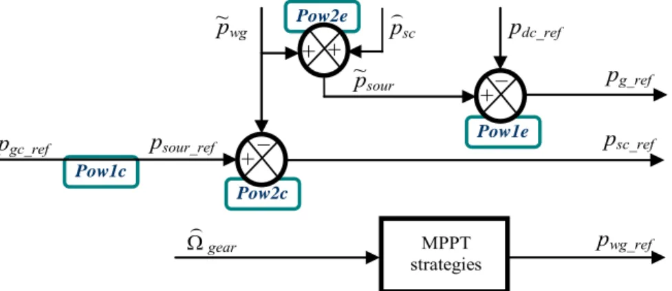
II.1.5 Power control unit... 37
II.1.6 Mode control unit... 40
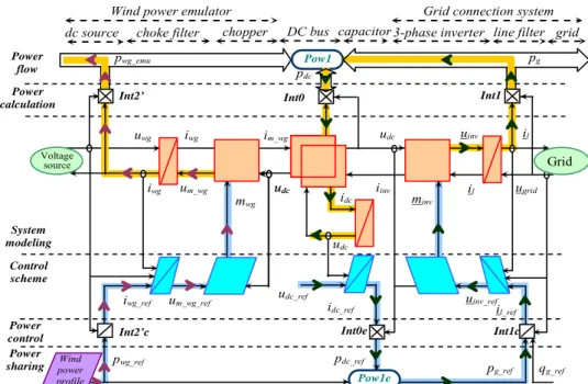
II.2 Experimental test of the grid connection control... 41
II.2.1 Wind power emulator... 41
II.2.2 Experimental implementation ... 43
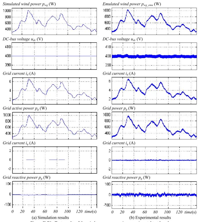
II.2.3 Simulation and experimental results ... 44
II.2.6 Discussion ... 45
II.3 Study of a wind/super-capacitor hybrid power generator ... 46
II.3.1 Presentation... 46
II.3.3 Modeling of the hybrid power system ... 48
II.3.4 Hierarchical control of the hybrid power system... 49
II.3.5 Power balancing strategies of the wind/super-capacitors hybrid power system ... 52
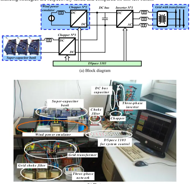
II.4 Experimental test of the wind/super-capacitor hybrid power generator... 55
II.4.1 Experimental implementation ... 55
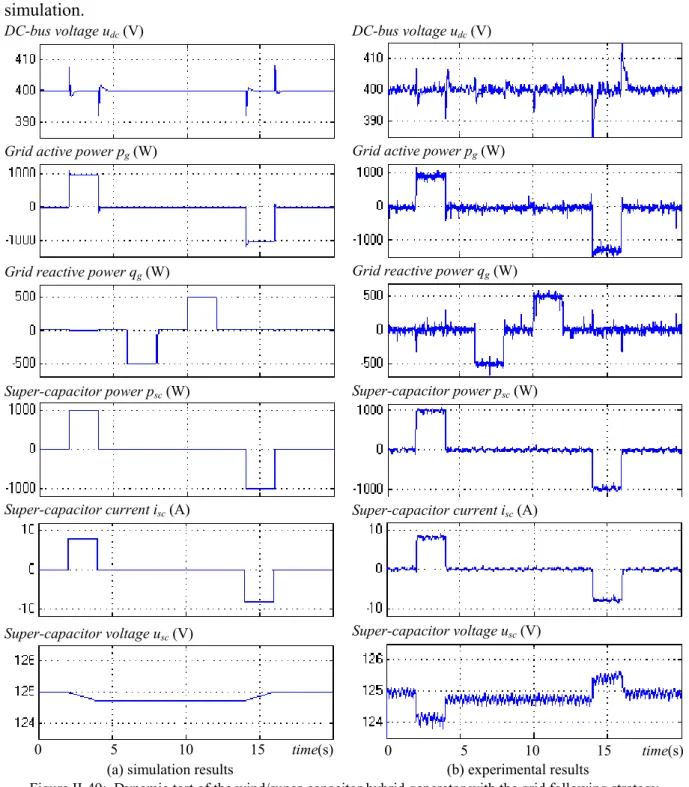
II.4.2 Test of the grid following strategy ... 56
II.4.3 Test of the power dispatching strategy... 59
II.4.4 Discussion ... 62
II.5 Conclusion... 63
Chapter III Fuel Cell for Energy Backup from Hydrogen... 66
III.1 Overview of fuel cells ... 66
III.1.1 Technologies... 66
III.1.2 Operating principles... 68
III.1.3 Fuel cell system ... 69
III.1.4 Technical challenges... 70
III.1.5 Modeling methods ... 71
III.2 Studied fuel cell system ... 73
III.2.1 Introduction ... 73
III.2.2 System operation ... 73
III.3 Modeling of the fuel cell stack... 75
III.3.1 Open-circuit voltage ... 75
III.3.2 Operating voltage... 76
III.3.3 Stack modeling ... 77
III.3.4 Graphical representation... 77
III.4 Modeling and control of the auxiliary systems ... 78
III.4.1 Modeling and control of the power conditioning system ... 78
III.4.1 Modeling of the fuel processing system ... 79
III.4.2 Modeling and control of the oxidant processing system ... 79
III.4.3 Modeling and control of the thermal management system... 80
III.4.5 Overall control and supervision system... 81
III.5 Modeling simplification and identification... 84
III.5.1 Simplification of the modeling ... 84
III.5.2 Experimental characterization of the fuel cell behavior ... 84
III.5.3 Identification of the modeling parameters ... 85
III.5.4 Dynamic limitations in transient states... 85
III.6 Real-time fuel cell emulator... 86
III.6.1 Structure of the fuel cell Emulator... 86
III.6.2 Modeling and control of the fuel cell emulator ... 87
III.6.3 Implementation of the fuel cell emulator... 88
III.6.4 Experiment results ... 89
III.7 Conclusion ... 90
Chapter IV Electrolyzer for Energy Storage into Hydrogen ... 92
IV.1 Overview of electrolyzers... 92
IV.1.1 Technologies ... 92
IV.1.2 Operating principles ... 93
IV.1.3 System performance ... 94
IV.1.4 Commercialized products... 96
IV.2 Studied electrolyzer system ... 97
IV.2.1 Introduction ... 97
IV.2.2 System operation ... 98
IV.2.3 Experimental tests ... 98
IV.3 Modeling of the electrolyzer stack... 99
IV.3.2 Operation voltage ... 100
IV.3.3 Stack modeling ... 100
IV.3.4 Graphical representation... 101
IV.4 Modeling and control of the auxiliary systems... 101
IV.4.1 Power conversion system ... 101
IV.4.2 Hydrogen handling system ... 103
IV.4.3 Oxygen handling system ... 104
IV.4.4 Water and thermal management system... 105
IV.4.5 Macroscopic representation of the electrolyzer system... 106
IV.5 Modeling simplification and identification... 106
IV.5.1 Simplification of the modeling... 106
IV.5.2 Experimental characterization of the electrolyzer behavior ... 107
IV.5.3 Identification of the modeling parameters... 107
IV.5.4 Dynamic limitations in transient states... 108
IV.6 Real-time electrolyzer emulator... 109
IV.6.1 Structure of the electrolyzer emulator ... 109
IV.6.2 Modeling and control of the electrolyzer emulator ... 110
IV.6.3 Implementation of the electrolyzer emulator... 111
IV.6.4 Experimental results ... 113
IV.7 Conclusion ... 113
Chapter V Active Wind Generator... 116
V.1 Modeling of the active wind generator ... 116
V.1.1 Presentation... 116
V.1.2 Equivalent average modeling... 117
V.1.3 DC-bus modeling... 118
V.1.4 Energetic macroscopic representation ... 118
V.2 Control of the active wind generator... 119
V.2.1 Hierarchical control structure ... 119
V.2.2 Automatic control unit ... 120
V.2.3 Power control unit... 121
V.3 Power balancing strategies for the active wind generator... 123
V.3.1 Role of the power balancing ... 123
V.3.2 Power flow modeling... 123
V.3.3 Grid following strategy... 124
V.3.4 Power dispatching strategy ... 126
V.4 Experimental tests ... 127
V.4.1 Experimental implementation... 127
V.4.2 Test of the grid following strategy... 129
V.4.3 Test of the power dispatching strategy ... 131
V.4.4 Comparison and discussion ... 133
V.5 Energy management of the active wind generator ... 134
V.5.1 Studied microgrid ... 134
V.5.2 Energy management ... 135
V.5.3 Mode control unit... 136
V.5.4 Normal operating mode ... 139
V.5.5 Short-term recovering modes... 140
V.5.6 Long-term recovering modes... 141
V.5.7 Entire recovering modes ... 143
V.6 Performance tests of the energy management strategies... 144
V.6.1 Presentation... 144
V.6.2 Normal operating mode ... 144
V.6.3 Short-term recovering modes... 146
V.6.4 Long-term recovering modes... 148
V.6.6 Efficiency analysis... 151
V.6.7 Cost evaluation ... 152
V.7 Conclusion ... 153
Conclusion... 157
Appendix ... 165
Appendix A: The ongoing research & development on Distributed Generation ... 165
Appendix B: Equivalent Continuous Modeling of Power Converters... 167
Appendix C: Control Structure of Power Systems through Power Converters ... 173
Appendix D: Causal Ordering Graph (COG)... 175
Appendix E: Energetic Macroscopic Representation (EMR) ... 177
Appendix F: Multi-Level Representation (MLR) ... 179
Appendix G: Hardware In-the-Loop (HIL) Simulation ... 187
Appendix H: Ancillary Services in the Context of Microgrid ... 191
Appendix I: Technical Data of the Used Super-Capacitors ... 195
Bibliography: ... 200
Curriculum Vitae (english version) ... 208
Curriculum Vitae (version française)... 210
List of Figures
Figure I-1: Evolution of installed wind power and photovoltaic cell production in the world ... 7
Figure I-2: Overview of distributed generation (based on and of typical uses) ... 8
Figure I-3: Example for organizing distributed generators and loads by means of Smart grid and Microgrid .... 10
Figure I-4: Examples of wind electrolysis ... 13
Figure I-5: Example of a microgrid... 15
Figure I-6: Characteristic of different kinds of energy sources... 17
Figure I-7: Wind generator with power electronics ... 18
Figure I-8: Characterization of main energy backup systems ... 19
Figure I-9: Structures of hybrid power systems for distributed generation... 21
Figure I-10: Methodologies of the PhD work ... 25
Figure II-1: A classical variable-speed wind energy conversion system ... 28
Figure II-2: Experimentally recorded wind speed and wind power ... 28
Figure II-3: Equivalent average modeling of the power electronic converters ... 29
Figure II-4: EMR of the considered wind energy generation system... 29
Figure II-5: Blade characteristic: CT versus λ for a fixed blade angle... 30
Figure II-6: EMR of the grid connection system ... 31
Figure II-7: EMR of the DC bus ... 32
Figure II-8: EMR of the entire wind energy conversion system ... 32
Figure II-9: Hierarchical control structure of the wind energy conversion system ... 33
Figure II-10: Turbine power vs. speed ... 33
Figure II-11: Control scheme of the wind energy generation system. ... 34
Figure II-12: Block diagram of the oriented field control of the electrical machine... 35
Figure II-13: Control scheme of the grid connection system. ... 35
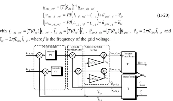
Figure II-14: Block diagram of the line current control in the grid connection system. ... 36
Figure II-15: Control scheme of the DC bus... 36
Figure II-16: Control scheme of the entire wind energy conversion system... 37
Figure II-17: Block diagram of the automatic control units for the wind energy conversion system. ... 37
Figure II-18: Power flow exchanges around the DC bus ... 37
Figure II-19: Power flow exchange inside the wind energy conversion system. ... 38
Figure II-20: Multi-Level Representation of the wind energy conversion system... 39
Figure II-21: Power flow balance and power sharing inside the wind energy conversion system... 39
Figure II-22: Block diagram of the hierarchical control for the wind energy conversion system... 40
Figure II-23: Equivalent average modeling of the power conversion chain with a wind power emulator... 41
Figure II-24: Power electronic stage of the wind power emulator. ... 41
Figure II-25: Multi-Level Representation of the wind power emulator. ... 41
Figure II-26: Implementation of the wind energy conversion experimental test bench... 43
Figure II-27: Multi-Level Representation of the wind energy conversion experimental test bench. ... 44
Figure II-28: Test results of the wind energy conversion experimental test bench... 45
Figure II-29: A wind/super-capacitor hybrid generator. ... 46
Figure II-30: Super-capacitor power conversion system... 46
Figure II-31: Equivalent average electrical modeling of the super-capacitor power conversion system ... 47
Figure II-32: EMR of the super-capacitor power conversion system modeling... 47
Figure II-33: Electrical model of super-capacitors... 48
Figure II-34: Equivalent electrical diagram of the wind/super-capacitors hybrid power system... 48
Figure II-35: EMR of the DC bus in the wind/super-capacitors hybrid power system. ... 48
Figure II-36: EMR of the wind/super-capacitors hybrid power system. ... 49
Figure II-37: Hierarchical control structure of the wind/super-capacitors hybrid power system... 49
Figure II-39: Block diagram of the automatic control unit for the wind/super-capacitors hybrid power system. 50 Figure II-40: Multi-Level Representation of the power modeling and control for the hybrid power system ... 51
Figure II-41: Block diagram of the hierarchical control for the wind/super-capacitors hybrid power system... 52
Figure II-42: Power flow balance inside the wind/super-capacitors hybrid power system... 52
Figure II-43: Power flow exchanges around the DC bus in the wind/super-capacitors hybrid power system ... 53
Figure II-44: Multi-Level Representation of the grid following strategy for the hybrid power system... 54
Figure II-45: Block diagram of the grid following strategy for the hybrid power system. ... 54
Figure II-47: Block diagram of the power dispatching strategy for the hybrid power system... 55
Figure II-48: Implementation of the experimental test bench for the hybrid power system. ... 56
Figure II-49: Dynamic test of the wind/super-capacitor hybrid generator with the grid following strategy... 57
Figure II-50: Evolution test of the wind/super-capacitor hybrid generator with the grid following strategy... 58
Figure II-51: Dynamic test of the wind/super-capacitor hybrid generator in power dispatching strategy ... 60
Figure II-52: Evolution test of the wind/super-capacitor hybrid generator in power dispatching strategy ... 61
Figure III-1: Schematic representation of a PEM fuel cell... 68
Figure III-2: Fuel cell system scheme ... 69
Figure III-3: Studied fuel cell system (Ballard NexaTM) ... 72
Figure III-4: Bloc diagram of a fuel cell system including the stack and its auxiliaries ... 74
Figure III-5: COG and EMR of a fuel cell stack modeling ... 77
Figure III-6: EMR and block diagram of the power conditioning modeling and control... 78
Figure III-7: EMR of fuel processing modeling as an energy source... 79
Figure III-8: EMR of oxidant processing modeling as an energy source... 79
Figure III-9: EMR of oxidant processing modeling and control ... 80
Figure III-10: EMR of the thermal management modeling and control... 81
Figure III-11: EMR of the fuel cell system modeling and control ... 82
Figure III-12: EMR of a simplified fuel cell system’s modeling and control ... 84
Figure III-13: The fuel cell stack current-voltage characteristics curves for different temperatures... 84
Figure III-14: Comparison between the modeling curve and experimental curve of the fuel cell stack in 65°C. 85 Figure III-15: Evolution of the electrical variables with a limited slope... 86
Figure III-16: Structure of the fuel cell emulator ... 87
Figure III-17: EMR of modeling and control scheme for the fuel cell emulator and power conditioning unit.... 87
Figure III-18: Experimental implementation of the fuel cell emulator ... 89
Figure III-19: Time evolution of the emulated variables ... 90
Figure IV-1: Electrical characteristic of different types of electrolyzers ... 92
Figure IV-2: Alkaline electrolyzer designs ... 93
Figure IV-3: Operating principles of electrolyzers ... 94
Figure IV-4: Influence of the temperature and the current on voltage efficiency and current efficiency ... 94
Figure IV-5: Studied electrolyzer system (CETH GENHY 100®)] ... 97
Figure IV-6: Block diagram of the simplified electrolyzer system. ... 98
Figure IV-7: Evolution of the main variables in the electrolyzer stack... 99
Figure IV-8: COG and EMR of an electrolyzer stack modeling... 101
Figure IV-9: EMR and block diagram of the power conversion system modeling and control... 102
Figure IV-10: EMR of the hydrogen handling system modeling... 103
Figure IV-11: EMR of the oxygen handling system modeling. ... 104
Figure IV-12: EMR of the water and thermal management system modeling... 105
Figure IV-13: EMR of the electrolyzer system modeling. ... 106
Figure IV-14: Simplified EMR of the electrolyzer system modeling and control. ... 106
Figure IV-15: Experimental current-voltage characteristics at 7bar with different temperatures ... 107
Figure IV-16: Experimental current-voltage characteristics at 45°C with different pressures... 107
Figure IV-17: Comparison between the modeling curve and experimental curve at 7bar and 45°C ... 108
Figure IV-18: Evolution of the simulated electrical variables with limited slope... 109
Figure IV-19: Structure of the Electrolyzer emulator ... 110
Figure IV-20: EMR of modeling and control scheme for the electrolyzer emulator. ... 110
Figure IV-21: Implementation of the electrolyzer emulator ... 112
Figure IV-22: Time evolution of the emulated variables ... 113
Figure V-1: Structure of the active wind generator... 116
Figure V-2: Equivalent electrical diagram of the active wind generator... 117
Figure V-3: EMR of the DC bus in the active wind generator... 118
Figure V-4: EMR of the power conversion system in the active wind generator ... 119
Figure V-5: Hierarchical control structure for the active wind generator. ... 119
Figure V-6: EMR of the active wind generator with the control scheme... 120
Figure V-7: Block diagram of the automatic control units for the active wind generator... 120
Figure V-8: Multi-Level Representation of the power modeling and control for the active wind generator ... 122
Figure V-9: Block diagram of the hierarchical control system of the active wind generator... 122
Figure V-11: Power balance inside the active wind generator... 124
Figure V-12: Multi-Level Representation of the grid following strategy for the power sharing ... 125
Figure V-13: Block diagram of the grid following strategy for the power sharing... 126
Figure V-14: Multi-Level Representation of the power dispatching strategy for the power sharing... 126
Figure V-15: Block diagram of the power dispatching strategy for the power sharing. ... 127
Figure V-16: Implementation of the experimental test bench for the active wind generator. ... 128
Figure V-17: Time evolution of the powers inside the active wind generator with the grid following strategy 130 Figure V-18: Time evolution of the storage systems’ currents and voltages with grid following strategy... 131
Figure V-19: Time evolution of the powers inside the active wind generator with power dispatching strategy 132 Figure V-20: Time evolution of the storage systems’ currents and voltages with power dispatching strategy . 133 Figure V-21: Studied microgrid ... 135
Figure V-22: Block diagram of the Mode Control Unit for the active wind generator... 137
Figure V-23: Hysteresis control of the short-term recovering modes. ... 138
Figure V-24: Hysteresis control of the long-term recovering modes for the active wind generator. ... 139
Figure V-25: Block diagram of the power dispatching strategy in normal mode . ... 140
Figure V-26: Block diagram of the power dispatching strategy in “full-SC” mode ... 140
Figure V-27: Block diagram of the power dispatching strategy in “empty-SC” mode... 141
Figure V-28: Block diagram of the power dispatching strategy in “full-H2” mode ... 142
Figure V-29: Block diagram of the power dispatching strategy in “empty-H2” mode... 143
Figure V-30: Test of the energy management strategy for the active wind generator in normal mode ... 145
Figure V-31: Test of the energy management strategy for the active wind generator in “full-SC” mode ... 146
Figure V-32: Test of the energy management strategy for the active wind generator in “empty-SC” mode... 147
Figure V-33: Test of the energy management strategy for the active wind generator in “full-H2” mode ... 148
Figure V-34: Test of the energy management strategy for the active wind generator in “empty-H2” mode... 149
List of Tables
Table I-1: Comparison of future’s Smart Grid with today’s grid... 10
Table II-1: Power calculation and control algorithms for the wind energy conversion system. ... 38
Table II-2: Power calculation and control algorithms for the wind/super-capacitors hybrid power system. ... 51
Table III-1: Overview of the operating characteristics of the different fuel cells ... 67
Table III-2: Summary of major FC modeling features... 72
Table III-3: Change in Gibbs free energy of hydrogen fuel cell at various temperatures at standard pressure.... 75
Table III-4: Summary of modeling equations and control algorithms for the oxidant processing... 79
Table III-5: Summary of modeling equations and control algorithms for the oxidant processing... 80
Table III-6: Summary of modeling equations and control algorithms for the oxidant processing... 81
Table III-7: Summary of modeling equations and control algorithms for the fuel cell emulator... 87
Table III-8: Parameters of the Fuel Cell Emulator... 89
Table IV-1: Technical comparison between alkaline electrolyzers and PEM electrolysers... 94
Table IV-2: Main manufacturers of electrolyzer, developed technologies ... 96
Table IV-3: Summary of modeling equations and control algorithms for the oxidant processing... 102
Table IV-4: Modeling parameters of the electrolyzer stack at 45°C and 7bar ... 108
Table IV-5: Summary of modeling equations and control algorithms for the fuel cell emulator... 110
Table IV-6: Parameters of the electrolyzer emulator ... 112
Table V-1: Power calculation and power control algorithms for the active wind generator... 121
Table V-2: Implementation parameters for the fuel cell and the electrolyzer emulators ... 129
Table V-3: Implementation parameters for the super-capacitors bank ... 129
Table V-4: Fast-dynamic energy storage level vs. the super-capacitor voltage ... 137
Table V-5: Long-term energy storage level vs. the hydrogen pressure in the tank... 138
Table V-6: Possible operating modes (M) for the active wind generator... 139
Table V-7: The round-trip efficiency of the storage systems... 152
Table V-8: Possible system efficiencies according to different energy distribution ratios ... 152
Table V-9: Techno-economic statistics of different components ... 153
Nomenclature of Symbols
x Variable
x) Measured value of the variable x
x
~ Estimated value of the variable x
xref Reference value of the variable x
Introduction
More and more decentralized generation systems are integrated into electrical network, as result, new structures of the electrical system should be considered. The microgrid is one of the solutions. The advantages of the microgrids consist of
- the association of the local generators and local loads in order to minimize the energy losses in the electricity transport;
- the possibility of electricity and heat cogeneration in order to increase the energy generation efficiency;
- the ease of using communication means in order to optimise the total electricity generation and to increase the quality and the reliability of the power system.
Nowadays, it is preferred to integrate renewable energies in the microgrid in order to reduce
the CO2 emission and the fossil fuel consumption. But the renewable energy sources are
usually very intermittent and fluctuant. Moreover the renewable energy production is generally difficult to predict. The power balance between the production and the consumption becomes very difficult. In order to increase the development of renewable energy generators in the electrical network, we must imagine new renewable energy generators, which are more flexible and more controllable for the grid operation.
The topic of this thesis is the transformation of a renewable energy generator into an active generator by using energy storage systems. A hybrid power system is studied in the thesis. It consists of a wind generator (as primary energy source), super-capacitors (as fast-dynamic storage system), fuel cells and electrolyzers (as long-term storage system in the form of hydrogen). They are all connected to a common DC bus and an inverter is used for the connection of the whole system to the grid.
The objective of this thesis is to design the control system, including the power balancing and energy management strategies for all embedded sources. The proposed active wind generator is able to supply controllable powers as most conventional power plants. As result, it is able to provide ancillary services to the electrical system of the microgrid [Appendix H].
The context of the thesis is introduced in the first chapter. And then the thesis work is presented in four chapters.
In Chapter II, a wind energy conversion system is studied. The system modelling and the control design are detailed. In order to overcome the fluctuation problems of the wind power, a super-capacitor based fast-dynamic storage system is added. Power balancing strategies are proposed for their coordination in this hybrid power system. The delivered power to the grid is well smooth, but the operation can not be ensured for a long time. Hence a hydrogen based long-term storage system (including the fuel cells and the electrolyzers) is considered in the following chapters.
In Chapter III and in Chapter IV, the studies of a fuel cell system and of an electrolyzer system are presented. The system modelling and the control design are studied and validated
by some experimental tests on the commercial systems (1200W Ballard Nexa fuel cell system and 500W CETH GENHY electrolyzer system). In order to set up a flexible experimental platform, some real-time emulators are built for the fuel cell and the electrolyzer by using validated models. These emulators can provide the same electrical behaviours as the fuel cell and the electrolyzer. This allows us to test the power balancing strategies in the active wind generator, which is presented in the following chapter.
In Chapter V, the study of the active wind generator is presented. The modeling and control of the entire system are detailed. The power balancing strategies are proposed according to the characteristics of each energy source. They are experimentally implemented in the digital control board (DSpace 1103), and their performances are compared with respect to the DC-bus voltage regulation and the grid power control. The energy management strategies are implemented in order to ensure the good energy availability. They are performed with different operating modes to adjust the required energy storage levels.
The conclusion and the perspectives of this thesis are finally presented in Chapter VI. The main scientific contributions of this thesis are the followings:
- the use and the adaptation of the graphical tools for the modeling of complex systems and their control design;
- the design and the experimental implementation of real-time emulators in order to reduce the time and the cost of an experimental test bench;
- The proposition and the validation of two power balancing strategies for the active wind generator to regulate the DC-bus voltage and to control the grid power;
- The proposition of different energy management strategies with the definition of the operating modes for the active wind generator to ensure the energy availibility.
These contributions can be adapted and extended for other hybrid power systems, which consist of a renewable energy source, a fast-dynamic energy storage system and a long-term energy storage system.
Chapter I
Context and Methodologies
Chapter I Context and Methodologies
In the last decades, Renewable Energy Sources (RES) and Distributed Generation (DG) have attracted special attention in Europe and all over the world, in order to reach two goals:
- Increasing the security of energy supply by reducing the dependency on imported fossil fuels such as oil, natural gas and coal;
- Reducing the emission of greenhouse gases, specifically carbon dioxide, from the burning of fossil fuels.
In the mean time, new concepts and technologies are being developed in the Transmission and Distribution Networks (like Smartgrid) and in the management and control concepts (like
Microgrid), in order to improve the grid integration and the local consumption of these
distributed renewable energy generators. Controllable and reliable generators are necessary in order to make all these concepts above feasible and flexible. In this PhD thesis we propose the association of a wind generator, super-capacitors and hydrogen technologies to assess an active generator for a microgrid application.
So before presenting this generator, this chapter recalls some concepts about renewable energy sources, distributed generators, smart grids and microgrids. Then in a second part, characteristics and opportunities of hydrogen as alternative energy carrier to electricity is presented. Hence, the context, which is related with microgrid and active generators, is explained as well as the structure of the active generator. Finally, the objectives of the research work and the followed methodologies are presented.
I.1 Renewable energy sources and distributed generation
I.1.1 Renewable energy sources
Renewable Energy Sources (RESs) refer to the sustainable natural energy sources, such as the sun and the wind. Renewable energy systems convert these natural energy sources into consumable energy forms (electricity and heat), which are easy to transport and to use. According to the European directive on RES for production of electricity [Dir 01], RESs include:
- Wind;
- Solar (photovoltaic, thermal electric); - Geothermal;
- Wave and tidal energy; - Biodegradable waste;
- Biomass (solids, biofuels, landfill gas, sewage treatment plant gas and biogas).
Nowadays, hydropower and wind power are technically and economically the best renewable energy utilizations. In countries with hydropower potential, small hydro turbines are used at distribution level to sustain the utility network in dispersed or remote locations. In many countries, the wind power potential has led to a fast development of wind turbine technologies in the last decade [Ewe 05]. A total amount of nearly 120GW wind power has been installed in the world by the end of 2008 (Fig.I-1a). Another renewable energy based sustainable power supply is the photovoltaic (PV) technology [Iea 05]. The number of PV
installations increases exponentially and the worldwide PV cells production reaches 3.7GW (Fig.I-1b), mainly thanks to the governments and utility companies that support programs focusing on grid-connected PV systems.
The main advantage of renewable energy systems is the low impact on the environmental pollution as no fossil fuels are involved. An additional advantage is the insensitivity to fuel prices since they are free natural resources. This decreases the operational cost of renewable energy systems and reduces economic operation risks.
The major drawback is the initial investment in renewable energy systems. It is often more expensive to build renewable energy systems than non-renewable energy systems, since the environmental deterioration has not yet been taken into account for the cost calculation. However, this investment cost will be reduced with the fast developing technologies (just like the development of computer industry in the last three decays). Other disadvantages of RES are the specific requirements of the site and the unpredictability of the generated power. The intermittent availability of the RES means a higher cost for balancing the electricity and for maintaining reserve capacity, for example in the event that the wind drops below or increases above the operating area of wind turbines. These quality and security problems have already been encountered in areas with a high penetration of wind turbines, such as in Germany and in Denmark.
2,9 4,8 6,1 7,6 9,8 13,5 17,7 24,5 31,4 39,4 47,5 59,5 74,4 93,9 3,5 120,8 0,0 20,0 40,0 60,0 80,0 100,0 120,0 1993 1994 1995 1996 1997 1998 1999 2000 2001 2002 2003 2004 2005 2006 2007 2008 (a) Total wind power installed in the world since 1993 (in GW)
69,1 77,6 88,6 125,8 154,9 199,9 288,5 401,4 557,8 759,0 1196,0 1771,2 2473,7 3733,0 69,4 0,0 500,0 1000,0 1500,0 2000,0 2500,0 3000,0 3500,0 4000,0 1993 1994 1995 1996 1997 1998 1999 2000 2001 2002 2003 2004 2005 2006 2007
(b) Total photovoltaic cell production in the world since 1993 (in MW)
I.1.2 Distributed generation
Distributed Generation (DG) refers to distributed energy generation and energy storage (like electricity and heat, near to or at the load center). Generally, a part of the electricity is used locally and the remainder is delivered to the grid. The heat, on the other hand, is always used locally, as heat transport is costly and involves relatively large losses. In this dissertation, we focus on the generation of electricity. DGs are usually smaller than 50 MW and are connected to the distribution network, which has a low or medium operating voltage level (240/400 up to 110kV). Fig.I-2 gives an overview of DG systems and their typical uses.
Figure I-2: Overview of distributed generation (based on [Ack 01] [Van 05] and of typical uses)
Today, central electricity production still dominates electricity production because of many issues, like economy of scale, efficiency, fuel capability and lifetime [Wil 00]. However, the advantage of the central production’s economy of scale is decreasing, because fossil fuels, which are economically suitable for central production, are not abundant enough for the next century (without steady supply or stable price). Recently, the world has shown its great interest and ambition of integrating RES and DG into the Transmission and Distribution Network (electrical grid) because of many advantages. These advantages include additional energy-related benefits (improved security of supply, avoidance of overcapacity, peak load reduction, reduction of grid losses) and network-related benefits (transmission network infrastructure cost, power quality support, reliability improvement) [Sch 03]. Moreover, DG can increase the overall fuel efficiency of the plant considerably, as the heat can be used locally. Appendix A outlines the ongoing research, development and demonstration (RD&D) efforts currently in progress in Europe, the United States, Japan and Canada.
Except for large-scale hydro, offshore wind farms and co-combustion of biomass in conventional (fossil fuelled) power plants, most renewable energy systems are small DG systems. In the last decades, electric power systems undertook several modifications toward a more decentralized energy system paradigm, allowing the increase of DG integration. With the fast development of distributed renewable energies, many efforts should be done in the following domains:
- Modernization of the Transmission and Distribution (T&D) networks (like SmartGrid), for distributed renewable energies’ grid integration;
- Innovation of the local system’s Management and Control Concepts (like Microgrid), for distributed renewable energies’ local demand and supply optimization;
- Implementation of Controllable and Reliable Generation (like Active Generators), to overcome the intermittent and fluctuant availability of renewable energies and to supply ancillary services to the electrical network.
In this context, we propose solutions to transform a wind generator into a controllable production unit.
I.1.3 Smart grid
Today’s electrical grid has to take the challenges to match the modern digital economy and information age, which requires higher load demands, uninterruptible power supplies, and other high-quality, high-value services. Especially, the integration of more and more DGs based on intermittent and fluctuant RES will lead to reliability problems of ancillary service, power quality disturbances, brownouts, and blackouts. The original power grid technology has its control systems embedded in the generating plants. The utilities attempt to meet the demand and succeed or fail with varying degrees (brownout, rolling blackout, uncontrolled blackout). The total amount of power loaded by the users can have a very wide probability distribution, which requires a lot of spare generating plants in standby mode to respond to the rapidly changing power usage. Thus, the clusters’ generating capacity should usually be oversized, so it is very expensive for the power producers, and the resulted brownouts and outages can be also very costly for consumers.
As new electricity transmission and distribution network is required for integrating the newly emerging distributed renewable energies. Smart Grid is a modernized “grid” that uses robust two-way communications, advanced sensors and distributed computers to improve the efficiency, reliability and safety of power delivery and use. With the application of communication and information technologies to the electric grid, many smart digital meters can be integrated in the modernized grid to replace analog mechanical meters. The Smart Grid System Operator (SGSO) is able [Maz 03]:
- to control the electrical powers down to the residential level, small-scale DGs and storage devices;
- to communicate information on operating status and needs and to collect information on prices and grid conditions;
- to transform the grid under central control into a collaborative network.
Moreover, the Demand Response (DR) will be the next step for the smart grid development. This can be very simple like timers to switch off electric water heaters during peak-demand periods, but such systems are unable to respond to contingencies. The full Smart Grid allows generators and loads to interact in real time, by using modern communication and information technology. So the demand managements can eliminate the cost of generators, can cut the wear and extend the life of equipment and allow users to get more value from the system by putting their most important needs first.
Table I-1: Comparison of future’s Smart Grid with today’s grid [Glo 05]
20th Century Grid 21st Century Smart Grid
Electromechanical Digital
One-way communications (if any) Two-way communications
Built for centralized generation Accommodates distributed generation
Radial topology Network topology
Few sensors Monitors and sensors throughout
“Blind” Self-monitoring
Manual restoration Semi-automated restoration and, eventually, self-healing
Prone to failures and blackouts Adaptive protection and islanding
Check equipment manually Monitor equipment remotely
Emergency decisions by committee and phone Decision support systems, predictive reliability
Limited control over power flows Pervasive control systems
Limited price information Full price information
Few customer choices Many customer choices
I.1.4 Microgrid
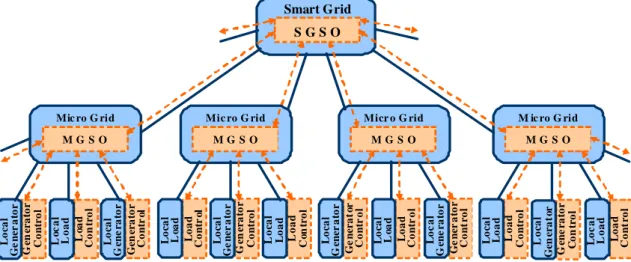
With a large number of widely dispersed distributed generators, the real-time communication and control are difficult to perform for the whole power system, especially with extremely large amounts of information and long transmission distance. Therefore, the optimized real-time control and management of distributed generators and loads should be implemented within local power systems. The necessary information should be firstly gathered and then be exchanged with the Grid System Operator (GSO) for the whole power grid’s control and optimization. As a new control and management concept of organizing the distributed renewable energies and local loads, microgrids have attracted great attention all over the world. An example of organizing all distributed generators and loads by means of smart grid and microgrids in a hierarchical structure is shown as in Fig.I-3.
M G S O M ic ro G rid M G S O Micr o G rid M G S O Mic ro G rid M G S O Mic ro G rid S G S O Smart Grid Lo c a l Lo a d Lo a d Co n tr o l Lo ca l Ge n e ra to r Gen era to r Co n tr ol Lo ca l Ge ne r a to r G en era to r Co n tr o l Lo ca l Ge ne r a to r G en era to r Co n tr o l Lo ca l Lo a d Lo a d Co n tr o l Lo ca l Lo a d Lo a d Co n tr ol Lo ca l Lo a d Lo a d Co n tr o l Lo ca l Ge n er a to r G e n era to r Co n tr o l Lo c a l Ge n e ra to r Ge ne r a to r Co n tr o l Lo ca l Gen era to r Ge n e ra to r Co n tr o l Lo ca l Lo a d Lo a d Co n tr o l Lo c a l Lo a d Lo a d Co n tr o l
The power connections are presented by the bold lines, which symbolize the infrastructure network. The Smart Grid interfaces many microgrids and each microgrid combines locally the dispersed generators and load, which are totally or partially controllable. The information connections are presented by the dotted lines, which symbolize the advanced communication technologies connecting Smart Grid System Operator (SGSO), MicroGrid System Operator (MGSO) and the controllers of distributed generators and loads
Microgrids comprise dispersed energy resources (like wind turbines, photovoltaic panels, fuel cells, micro gas turbines…), storage devices (like flywheels, super-capacitors and batteries) and controllable loads in order to offer considerable control capabilities to the local network operation. These systems are interconnected to the low-voltage distribution network, but they can also be operated in islanding mode in case of faults in the upstream network. From the customer’s point of view, microgrids provide both thermal and electricity supplies, and in addition enhance local reliability, reduce emissions, improve power quality by supporting voltage and reducing voltage dips, and potentially reduce costs of energy supply. A series of microgrid symposiums have started in California, on 17 June 2005, and then have been organized in Montreal on 23 June 2006, in Nagoya on 6 April 2007 and recently in Kythnos on 2 June 2008. The main researches include control philosophies, energy management, local generator and load issues and analysis tools…
Islanded operation is expected to happen very few times in a year and it is obvious that the main concern is to “keep the lights on” in such periods. In interconnected operation, MicroGrid System Operator (MGSO) should ensure the maximization of renewable energy generation and the optimization of the microgrid’s operation. Controller functions have to be considered in order to achieve optimal operation of the microgrid in interconnected mode. The MGSO might use load forecasts (electric and possibly heat) and production capacity forecasts (from local generators). It uses the market prices of electricity, the gas costs, the local production capability, the local load demands, the grid security concerns and the distribution network’s requests to determine the amount of power that the microgrid should draw from its owned distributed generators and another amount of power that should be exchanged with the upstream grid network. The defined optimized operating profile can be achieved by controlling the local generators and the local loads in the microgrid by sending control signals to their controllers. In this framework, non-critical, controllable loads can be cut off, when necessary. Furthermore, it is necessary to monitor the actual active and reactive power balancing. These techniques can be considered equivalent to the secondary control of the interconnected grid [Tsi 05].
Many technical challenges are associated with the operation and the control of microgrids. Energy management is very important for the achievement of good energy efficiencies by optimizing production and consumption of heat, gas and electricity. With various conflicting requirements and limited communication techniques among a large number of distributed energy sources, the management of instantaneous active and reactive power balancing is a key challenge of microgrids. Another key challenge of microgrids is to ensure stable operation during faults and various network disturbances. Transitions from interconnected operation to islanding operation are likely to cause large mismatches between generations and loads, and to cause severe frequency and voltage control problems. Maintaining stability and power quality in the islanding mode of operation requires the development of sophisticated control strategies.
In this context, we propose to design a local control interface of a wind generator based hybrid power system in order to make it available for the microgrid management.
I.1.5 Hybrid power system
Because of the intermittent and fluctuant availability of the renewable energy sources, Hybrid Power Systems (HPS) provide a high level of energy security through the mix of various generation systems and often incorporate energy storage systems to ensure maximum reliability of power supply. Several kinds of hybridization of power sources are presented as follows:
- Hybridization of renewable energy sources and backup power units: Because of the intermittent availability of renewable energy sources, backup power units are usually integrated for a high level of local energy security. For example, diesel generator, micro gas turbine and fuel cells are usually used as for uninterrupted power supplies [Che 03]. - Hybridization of renewable primary sources: Two or more renewable primary sources can
be associated for complementary advantages. For example, the PV-Wind system are often proposed, because the PV panels provide powers only in the day time and wind generators produce usually more powers with stronger wind in the night. [Ahm 06].
- Hybridization of renewable energy sources and energy storage devices: The association of energy storage devices with renewable energy sources can ensure reliability and security of the distributed power generation system while maximizing the benefit from renewable energies. For these systems, the excess and deficit of energy production can be optimally adjusted by the energy storage units to increase the energy efficiency [Abb 05].
- Hybridization of different kinds of energy storage devices: In this PhD thesis, we have classified energy storage devices into two categories: fast-dynamic storage devices and long-term storage devices. We propose an association of these two kinds of device to bring their complementary advantages to the renewable energy based generator for improvement of the power supply [Zho 07].
In this PhD thesis, a hybrid power system is proposed to assess an active wind generator in order to provide some ancillary services to microgrid.
I.2 Hydrogen as alternative energy carrier to electricity
I.2.1 Hydrogen market
Because of the effects of carbon emissions into the atmosphere on global climate change, a carbon-constrained world is coming and alternative energy sources will be required to supplement the carbon-intensive sources that currently power the utility network and the transport vehicles. One promising solution to this problem is the direct use of hydrogen. Hydrogen, is not a primary energy source like coal and oil, but is an energy carrier like electricity. Ideally, 1kg of hydrogen at 25°C and 1bar corresponds to 39kWh of electricity. But unlike electricity, hydrogen can be stored quite easily.
Hydrogen can be manufactured or extracted from hydrogen-rich materials such as coal, natural gas, biomass or water. Currently, the primary means of manufacturing hydrogen is to strip it from natural gas via steam methane reforming. The technologies to produce hydrogen
from non-fossil sources are also available, such as biomass, wind, and solar. As advantages, the hydrogen production cycle from non-fossil sources can produce less greenhouse gases than from fossil sources.
The current market for hydrogen is divided into two segments: captive users, who produce the hydrogen at the location where it is to be used; and merchant users, who have their hydrogen delivered to the point of use. In the worldwide, the captive market is larger, and includes chemical producers, refineries, fat and oil hydrogenation and metal production. The merchant market is smaller and serves industries such as electronics manufacturers, float gas producers and public utilities for generator cooling in nuclear plants [Sur 04].The future market for hydrogen is even much larger, if hydrogen is to be used as fuel for vehicles.
I.2.2 Hydrogen-electric economy
Hydrogen economy refers to a society that can use hydrogen as an energy carrier because of the following advantages:
- hydrogen can be produced from a clean energy sources; - hydrogen can be distributed and stored in a variety of ways;
- hydrogen can replace fossil fuels to provide electricity and transportation fuels;
- domestic resources can be used for hydrogen production to lead to energy independence. Such an idea is not new and it dates back up to 1874 “…Water will one day be employed as fuel, that hydrogen and oxygen of which the water is constituted will be used, simultaneously or in isolation, to furnish an inexhaustible source of heat and light”[Ver 01].
As in France, the all-electric economy relies on inexpensive nuclear electricity [Gre 72]. Additional means are required to modulate the electricity production with fast response time. Classically they are pumped-storage hydro and coal or oil based thermal generators. Both additional power-regulation means have their own drawbacks as the site-specific application, the increasing price of the fossil fuel and environmental pollution.
The use of hydrogen to replace fossil fuels and as an alternative to the all-electric
economy is examined. The term hydrogen-electric economy was also developed [Lot 74] to
describe the possibilities of combining production, transmission and sales of both energy carriers. Like electricity, hydrogen can be centrally produced and then be distributed to the point of use. It can also be produced locally (decentralized hydrogen production) (Fig.I-4).
If hydrogen can be produced economically, hydrogen-based internal combustion engines (IECs) and fuel cells could be used to provide electrical power in distributed energy applications. If the loads can also use the heat from the distributed generators, a combined heat and power (CHP) application can increase the overall efficiency of the packaged system. Moreover, new technological advantages may be developed:
- the electrolyzers can be used during off-peak times in order to increase the efficiency of the electrical power system by allowing it to run close to its rated capacity [Fer 74];
- the hydrogen, which is produced on site, can be used for generator cooling with its high thermal capacity and low density[Gre 73];
- For wind electrolysis, the wind tower may even be used as hydrogen storage tank [Kot 03].
I.2.3 Hydrogen as storage for electricity a) Hydrogen production from electricity
Hydrogen can be produced from a variety of sources. Currently, hydrogen is mainly produced by reforming natural gas and dissociating hydrocarbons and a smaller amount is produced by electrolysis. Reforming natural gas is currently the least expensive way to produce large quantities of hydrogen. However, some drawbacks exist:
- the process is based on a non-renewable fossil-fuel source; - the reactions produce also carbon dioxide;
- the produced hydrogen gas can have high impurities.
As another way, electrolysis uses direct current electricity to split water into its basic elements of hydrogen and oxygen. For large-scale energy storage, the hydrogen should be further compressed before stored. Since the electrolysis process uses only water and electricity, it can produce pure hydrogen and oxygen (99.9995%).
In the actual hydrogen market, electrolyzers are still used in places where low electricity prices are available or for high hydrogen purity requirements. As the price of natural gas increases, electrolysis becomes a viable option for competition in the hydrogen market and electric utilities are well placed to provide the electricity for hydrogen production by water electrolysis.
b) Electricity generation from hydrogen
Hydrogen can also be used to generate electricity in different ways. Hydrogen can be used as fuel to supply the combustion engine for electricity generation by rotating machine. Hydrogen can also be directly used through electro-chemical reactor (eg. fuel cells) to generate electricity. For high power levels, the most efficient conversion from hydrogen to electricity can be achieved in combined heat and power (CHP) plant, where the thermal energy can also be used. For lower power levels, fuel cells alone can be applied.
c) Round-trip evaluation
Fuel cells require very high hydrogen purity, so electrolyzers are very suitable for the application. Both components use direct electro-chemical conversion and higher round-trip efficiency can be expected (in the range of 35-40%) than using “steam methane reforming” (for hydrogen production) and “hydrogen combustion” (for electricity generation).
I.3 Integration of renewable energy based generators into a microgrid
I.3.1 General framework of the microgrid operation
In our study we consider a microgrid, which is powered by a gas micro-turbine (Fig.I-5). At first sight the use of Renewable Energy System can decrease the environmental impact. So we want to evaluate the integration of a wind generator into the operation and the management of the studied microgrid.
The microgrid can operate both in connected mode with a distribution network and in islanding mode. The MicroGrid System Operator (MGSO) controls the microgrid’s operation through the local generator controllers (Fig.I-3).
In connected operation, a timing power planning is established between the DSO and the MGSO. The MGSO adapts the power reference of the gas micro-turbine in order to fulfill this contract.
In islanding operation, the microgrid should ensure the local electricity supply and energy security. To perform the power balance between the production and consumption, the MGSO should predict the local production capacity and the local consumption needs for the next period. If the production is more than the consumption, the power production of the gas micro-turbine must be reduced and during this transient state the excess power is dissipated in dummy resistor loads in case of overvoltage. If the production is less than the consumption, two solutions exist. The micro gas turbine will be prepared to supply the deficit power or a part of loads will be disconnected from the microgrid (if necessary).
Micro Gas Turbine Microgrid MicroGrid System Operator (MGSO) Load Load Load Distribution Network Load Distribution System Operator (DSO) Load Load
Figure I-5: Example of a microgrid
I.3.2 Problems of renewable energy sources
Actual wind generators are not dispatched by a microgrid system operator because their output active and reactive powers are not controllable. In an isolated microgrid if a wind
generator is used the electrical production may exceed the consumed load power. This event may occur during the night when the loads are very low. This is a typical problem, which is a barrier for the integration of wind generator in grids. So research efforts must be done to transform this wind generator into a classical generator.
As example one desirable control action is to be able to reduce the wind power production when it is not useful for the microgrid operation. In order to increase the value of renewable energy, it is interesting to store locally the non-used electrical power. Another advantage of having load storage capability is to make able the supply of more power (as the wind turbine can) if the microgrid operator asks it.
Moreover the generated wind power is very fluctuant. So the gas micro-turbine has to perform a real time compensation of power transients and it implies abnormal stresses. Important collateral effects may decrease expected economic and environmental benefits. So a great improvement is to erase the wind-caused power variations by using a local storage unit with fast dynamic abilities. It should smooth the produced power. A local control system must manage the storage to supply or absorb the power difference between the generated wind power and the power reference set by the MGSO.
In connected mode, it is very important to have a constant power exchange with the grid during each period (15 or 30 minutes) between the microgrid and the distribution grid. If renewable energy based generators are connected, the MGSO must estimate the production capacity with the climate forecasts as well as the local consumption demands for the next period τn. To have a great benefit of “clean” electricity production we must imagine a possible
scenario. The MGSO should send to the DSO the average power, which will be exported
during the period τn . Hence the DSO has enough time in advance to gather and to send set
points to coordinate the power production for his interest. At the same time, the MGSO assigns the power references to each local generator for the period τn according to the climate
condition. Then each active generator should respect its power reference during the period τn,
against the possible large fluctuations of the weather condition.
These problems and possible solutions show the necessity to get a wind generator, which is capable of exchanging information with the MGSO and of supplying the power requirements of the microgrid.
I.3.3 Concept of active generator
The task of an active generator is to supply the electrical power references, which has been previously set by the MGSO for a given period by taking into account all the local factors and the distributed network’s requirements.
Conventional power plants are usually active generators because they are controllable and can supply necessary powers to satisfy the grid requirements. Moreover, they can usually provide some ancillary services to the grid, basically like frequency regulation by active power control, voltage regulation by reactive power control, etc… They are mostly fossil and nuclear fuelled and rely on the abundant fuel supply like coal, oil, natural gas or nuclear fuels. Most of the time, they can work at any power level below its nominal power (Fig.I-6a) by controlling the fuel supply.
Renewable energy generators are usually considered as passive generators because they can not participate to the grid management, because they are dependent on the availability of the primary renewable source. Most of the time, they work far below their nominal capacity (Fig.I-6b). Moreover, the reliability and efficiency of the power system can not be ensured.
Therefore, they can not provide ancillary services to the grid, like power balance between the production and the consumption.
Energy storage devices can serve as backup power plants. They can work at any power level between two nominal powers, for storing and releasing energies (Fig.I-6c). So they can be used to support the operation of sources, transmission, distribution, and loads. When they serve as source devices, they can help to solve the problems of renewable energies’ intermittent availabilities and fast transients.
For each unit, the classified power domain can be achieved by a proper control (Fig.I-6). Thus, a hybrid power system combining a renewable energy based generator and energy storage devices can be a good solution to make an active generator. Such an active generator corresponds to both the needs of clean energy generation and high power quality for the future’s electrical network. For this objective, two major innovative improvements should be made:
- Energy Storage Systems should be well chosen and associated with renewable energy
generators to compensate or to absorb the power difference between the actual renewable energy production and the required grid consumption;
- Energy Management Strategies should be properly designed and adapted to control the
power flows among the renewable energy generator, the energy storage systems and the grid. Various additional control functions have to be implemented to provide ancillary services for the grid [Appendix H].
Power
Time Nominal
Power
(a) Conventional plant
Power
Time Nominal
Power
(b) Renewable energy source
Power Time Nominal Power Nominal Power
(c) Energy storage system Figure I-6: Characteristic of different kinds of energy sources
With proper power control and energy management strategies, active generators must perform local optimization of the active and reactive power production and fast load tracking.
I.4 Presentation of the studied active generator
I.4.1 Technologies of wind generators
Among the different renewable energy generators, the wind generator is technically and economically the most developed one. In general, wind generators can be classified into three categories [Bla 06].
Wind generator without power electronic converters: Most of these topologies are based on a squirrel-cage induction machine (SCIM), which is directly connected to the grid. A soft starter is usually used to reduce the inrush current during start up. Moreover, a capacitor bank is necessary for the reactive power compensation (Fig.I-7a).
By adding power electronic converters into the wind generator, a variable-speed wind generator can be achieved. Although the system complexity and the solution cost are