HAL Id: hal-00781995
https://hal.archives-ouvertes.fr/hal-00781995
Submitted on 28 Jan 2013
HAL is a multi-disciplinary open access
archive for the deposit and dissemination of
sci-entific research documents, whether they are
pub-lished or not. The documents may come from
teaching and research institutions in France or
abroad, or from public or private research centers.
L’archive ouverte pluridisciplinaire HAL, est
destinée au dépôt et à la diffusion de documents
scientifiques de niveau recherche, publiés ou non,
émanant des établissements d’enseignement et de
recherche français ou étrangers, des laboratoires
publics ou privés.
comparative case study
Frédéric Segonds, Mehdi Iraqi-Houssaini, Lionel Roucoules, Philippe Veron,
Améziane Aoussat
To cite this version:
Frédéric Segonds, Mehdi Iraqi-Houssaini, Lionel Roucoules, Philippe Veron, Améziane Aoussat. The
use of early design tools in engineering processes : a comparative case study. International Journal of
Design and Innovation Research, IJDIR, 2010, pp.16. �hal-00781995�
The use of early design tools in engineering
processes: a comparative case study
F. Segonds
1, M. Iraqi-Houssaini
2, L. Roucoules
2, P. Véron
2, A.
Aoussat
11
Arts et Metiers ParisTech,
LCPI, EA 3927
151 boulevard de l’Hôpital, 75013 Paris, FRANCE Tel. +33 1 44 24 63 77
{frederic.segonds ; ameziane.aoussat}@ensam.eu
2
Arts et Metiers ParisTech,
LSIS, UMR CNRS 6168
2 cours des Arts et Métiers, 13617 Aix-en-Provence, FRANCE
{mehdi.iraqi-houssaini ; lionel.roucoules ; philippe.veron}@ensam.eu
ABSTRACT. Nowadays, product design is increasingly complex: not only must it answer customer needs through complex functions; it must also ensure traceability throughout the design process, keeping in mind that standards and stringent regulations must be complied with. Faced with new challenges, engineering practices have evolved to allow stakeholders to be able to manage projects in new work environments, especially during the early stages of design. After presenting a state of the art of early design tools used in product design and their integration in PLM context, we compare class diagrams for two of them : TDC software (Knowllence©) and RFLP module of CATIA V6 (Dassault Systems©). Then, our paper
presents an experiment focusing on these tools, which aims to assess their usability, to evaluate and compare them. Users can raise issues, take note of which functionalities are appreciated, and provide qualitative feedback. We analyze the results obtained in this experiment and propose a comparison based on four topics: learnability, satisfaction of users, efficiency and error correction. Finally, we present some links between class diagrams and usability of the tools.
KEYWORDS: early stages of design, software usability, interoperability, PLM.
1. Introduction: evolutions in product design
Nowadays, product design is increasingly complex: not only must it answer customer needs through complex functions; it must also ensure traceability throughout the design process, keeping in mind that standards and stringent regulations must be complied with. Today, the main problem is that each stakeholder of the design process works with his own tools. Although each of them, individually, has optimized his own work processes, issues often
occur when integrating work from different sources. This may be because the data format is not readable by other collaborators or because heterogeneous parts do not match together. In order to facilitate data exchanges, much research work has been carried out. For example, the STandard for the Exchange of Product model data (STEP) was created in 1983. It allows the capture and transfer of parameterized CAD models with geometric constraints, the transmission of behavioral information and the description of operations used to construct them [Pratt and Anderson, 2001]. Interoperability between tools, defined as the ability of two or more systems or components to exchange information and use this information [Geraci et al., 1991], is seldom achieved. One result of this is the multiplication of tools to support design, as well as that of constraints in the work environment, as shown in a recent study by [Delphi, 2010]. In this study, almost 40% of the persons interviewed say they spent more than 25% of the day searching for information. The Dassault Systems© CAD solution CATIA V6
intends to bring an in-depth solution to this problem of integration, by placing customer requirements at the heart of the design process. It aims to deliver high-function products to the market at a competitive cost. That is why requirements and functions must be integrated in system design from the very beginning. Indeed, studies have proven that more than 80% of the final cost of a design project is determined during its early design stages [Rush and Roy, 2000]. Therefore, collaboration in these steps must be encouraged.
Extracted motivations:
Based on the above discussions, we have extracted the following motivations for this study:
Motivation 1: all companies, and especially students, may need to become involved in the early stages of design, in the context of globalization and Business Process Outsourcing [Pezeshki et al. 2004]. Indeed, product design methodology is mainly learnt at the University or School of Engineering through CAD software, which are nowadays unable to cover this field.
Motivation 2: for these stages, there are currently few computational tools available to support design and to equip the early stages of design [Mougenot, 2008]. However, there has been recent progress in this field, and the issue is to choose, between the available tools, which is the most adapted to address user needs. It is well-known that many products are not designed to respond to end-user expectations, including the need for usability [Sagot et al. 2003], especially for design software.
Motivation 3: Integrated design environments [Tichkiewitch et al. 2007], covering the whole product lifecycle, are a significant source of competitiveness in the business world. Thus, it is not surprising that there is a focus of research in the academic world, and that tools are developed to meet these needs. Such evolutions in our way of designing products have been supported by the development of tools and methods, such as the implementation of PLM platforms in support of collaborative engineering.
The goal of this paper is to analyze the data models which are used in two software programs, which can be used in the early stages of design [Segonds et al. 2009]: TDC, from Knowllence©, and CATIA V6, from Dassault Systems© and especially the RFLP module, for
Requirements, Functional, Logical and Physical. We then correlate the analysis of these models with the results of user tests carried out on the same products. Finally, we give some conclusions regarding the ability of these tools to support the early stages of design.
2. State of the art: TDC and RFLP for product design in a PLM context
2.1. PLM and interoperability
In the early 2000s, Product Lifecycle Management (PLM) emerged as a solution to adapt industrial design to the demands of globalization. Indeed, as PLM addresses the entire lifecycle of the product, it has a cross-functional nature and deals closely with the way a company operates [Garetti et al. 2005]. Collaborative design has thus been the subject of numerous studies. With the development of PDM (Product Data Management), PLM [Berkooz 2007] and associated workflows, software firms have proposed solutions to the everyday problems of engineering design departments (e.g. versioning documents, naming them, etc.). PLM aims to cover all stages of product development, by integrating processes and people who take part in the project [Schuh et al. 2008]. This concept is generally used for industrial products. For Amann [Amann 2002], over the past several years, PLM has emerged as a term to describe a business approach to the creation, management, and use of product-associated intellectual capital and information throughout the product lifecycle. Thus, it is an approach in which processes are just as important as data, or even more. This approach can be viewed as a trend towards full integration of all software tools taking part in design and operational activities during a product’s lifecycle [Garetti et al. 2005 ; Donati et al. 2010]. Therefore, PLM software packages need product data management systems; synchronous and asynchronous, local and remote collaboration tools; and if necessary, a digital infrastructure allowing exchanges between software programs.
In this PLM context, one of the most important stages is the definition of customer needs [Aoussat 1990]. Requirements must then be traced across the various stages of development. In many industrial cases the succession of "Requirements → Engineering computations → Design → Production" is followed automatically, and it is of vital importance to provide engineers with the necessary feedback to iterate the design process [Sunnersjö et al. 2006]. Moreover, tests and system integration must be performed to verify that the proposed system complies with requirements. According to [Ballu et al. 2006], continuity between the different levels of modeling (functional, logical and physical) is fundamental to decrease data losses and to link specifications, parameters and models in different levels, to reduce omissions, errors and redundancies, and to guarantee compliance with specifications. Faced with these challenges, product design is a complex activity which involves numerous stakeholders intervening throughout the product lifecycle. Approaches to design are numerous and varied. The design process itself can be defined as a succession of actions born from a need which may or may not be expressed in formal terms, leading to the definition of a product (e.g. functions, geometry, etc.).
Today, collaborative product design is an essential means for businesses to create value. Classical tools in this area generally focus on the integration of product/process relationships and on exchanging information between design and manufacturing activities (strategies termed DfX, or “Design for X”). This integration approach, however, is not completely satisfactory in the case of engineering projects which involve multiple stakeholders and a wide array of fields of professional expertise. Furthermore, new approaches to collaboration go even further, as they consider the integration of semantic aspects of engineering systems to be a necessity in order to support the technical aspects of these systems.
Intermediary Representations [Bouchard et al. 2005] of a product are defined and manipulated using business tools, e.g. CAD software. In order to communicate with each other, tools such as CATIA rely on standard exchange formats like the STEP format [ISO
10303-21 1994 ; ISO 10303-203 1994]. However, there remain some issues of interoperability, both at the syntactic and the semantic levels. It thus becomes a necessity, when collaborating with multiple stakeholders, to clear a number of hurdles, notably:
- To process a range of heterogeneous knowledge regarding the product and its design process.
- To formalize knowledge and to facilitate interoperability between different business tools.
- To encourage multidisciplinary innovation using diversified business tools which are able to communicate with each other.
Interoperability, as defined by [Wegner 1996], is "the ability of two systems (or more) to communicate, cooperate, and exchange data and services, in spite of the differences in languages, implementation, and operating environments or abstraction models”. Depending on which point of view is considered, there are many possible definitions of interoperability:
- Syntactic interoperability relies on the implementation of information technology in order to present, to store, to exchange and to process data.
- Semantic interoperability must ensure that the data created by one business tool can be understood and interpreted by other business tools, while preserving its semantics.
- Organizational interoperability relates to the responsibilities, clearances, legal aspects, intellectual property, and organizational structures which are necessary for sharing data between different business tools and stakeholders.
Interoperability between business tools can be defined following three distinct points of view:
- Integration: all product models use the same standard or a shared representation as a hub to formalize these models. The representation is either non-standardized, or specific to a given business.
- Unification: one common data structure offers the possibility to establish semantic correspondences between different product models [Krause et al. 1993].
- Federation: several distinct product models are dynamically linked following one (or more) correspondence maps, based on several concepts which are related at the semantic level (relationships of similarity or equivalence).
Integration Unification Federation Standard
format vs
specific format
One standard format for all product
models.
Use of a standard or common format in an approach which is said to be unifying, but is more flexible than an integration approach. No common format or standard to establish interoperability. Comparison in terms of interoperability Each business expert must adapt his product model to the established format.
A means for semantic equivalence which allows establishing a correspondence map between all product models. Dynamic adjustment is compulsory in order to achieve interoperability by using a single ontology.
Table 1. Comparative analysis of the integration, unification, and federation approaches.
An integration approach, such as the one adopted by Dassault Systems© in its CATIA
software suite, relies on the development of a single ontology or standard format. This represents a compromise or consensus regarding the points of view of the various experts involved in collaboration. This approach has a number of drawbacks, including the following:
- Because of these compromises, the new ontology gives only limited compatibility with the data structures or meta-models used in the various business tools. This restricts the possibilities for interoperability between business tools.
- This integration approach implies an access to the various data structures or meta-models of the business tools used. This is not often the case in our current industrial context.
Unification approaches, although they are very much in favour at the moment, do present some limitations. Indeed, the required alterations of product models which are used by design experts, following the ontology which gives rise to the correspondence map between the models, implies rigorous management of the different versions of the product model. A federative approach allows exchanges between the various product models generated by different business tools, in an independent and progressive fashion. Today, the use of increasingly specialized tools following the unification or federative approaches allows us to provide experts with tools which are efficient and easy to handle, as shown by the study presented in this paper. Both approaches also allow a more accurate response to user needs.
The two tools which we will now study have not followed the same orientations for development. CATIA advocates the integration approach, while TDC favours a federative approach. Following a short presentation of both tools, we describe them in detail using their class diagrams to compare both approaches.
2.2. The TDC Suite
Currently, designers have many tools at their disposal, covering the whole design process from the definition of needs up to the production of the files for industrialization of the product. Most of the time, these methods are used in an autonomous and independent way. The TDC
suite tries to gather all these tools and to underline the relationships between the methods in order to improve the design process.
The TDC suite includes TDC Need, Structure, and FMEA, software which allows, respectively, External and Internal Functional Analysis, and running the FMECA (Failure Modes, Effects and Criticality Analysis) method. These three points of view complement each other and aim to improve design. During early stages of design, one must check that the product meets customer needs: these are translated into requirements by the designer, using TDC Need. The next step is searching for technical solutions and choosing the best one, using TDC Structure. Finally, the designer must verify the adequacy of the product to initial requirements, through TDC FMEA.
[Martin et al. 1999] have shown that the TDC Suite, which integrates different tools in a single black box, offers greater completeness in the information that is generated and collected, than might be achieved simply by adding up results from the tools taken separately. This is likely to help increasing the completeness of the design process by improving the integration of data and constraints from downstream services for product definition, but also by enforcing a greater consideration of initial specifications. Therefore, links between methods contribute to make the design process reliable.
The TDC system provides a wide range of collaborative platforms for systems engineering and project management. In prior work [Iraqi et al. 2011], the TDC Structure software program used for internal functional analysis has been studied. The goal of TDC Structure is to optimize product design based on service functions, defined using the software program TDC Need. We now focus on the RFLP module developed by Dassault Systems©.
2.3. RFLP, a new approach in product design through the digital chain
Collaborative design today lacks tools that are directed towards the early stages of design [Segonds 2011]. The emergence of the concept of RFLP (Requirements, Functional, Logical and Physical) provides this structure. Coordinated management can be achieved through integration of behavioral aspects in product definition and through functional traceability. It is based on three poles:
- Requirements engineering (R) i.e. to specify customer needs and to write corresponding specifications in terms of performance, security etc.
- The definition of an architecture solution (Functional, Logical, Physical):
- F: to distribute the different functionalities of subsystems in a system, in order to validate functions of the global system.
- L: to define a logical model to execute and analyze technological solutions corresponding to these functionalities.
- P: to associate each logical component to its 3D representation.
Traditional design methods often create a fragmented design process due to many disconnected and heterogeneous tools, and suffer from a lack of traceability between specification, implementation, testing, and validation of systems. CATIA V6’s RFLP module introduces a model, with the following improvements:
- Multidisciplinary needs are shared between collaborators during the different project phases.
- Traceability of needs from specification to the functional, logical and physical stages of product design.
- Behavior simulation of virtual systems for quick validation.
We will now compare the class diagrams of TDC and of CATIA’s RFLP module.
2.4. A comparison of class diagrams for TDC and RFLP
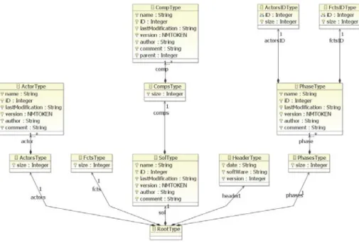
We define below the XML diagram [XML 2011 ; Michard 2000] of an extract of a file exported using TDC Structure. Figure 1 presents an extract of the TDC metamodel which corresponds to this diagram, obtained through the use of techniques from Model-Driven Engineering [Bézivin 2006 ; Steinberg et al. 2008]. The techniques used to obtain this model are presented in [Iraqi et al. 2011].
Figure 1. Extract of the TDC Structure metamodel.
Model-driven engineering (MDE) [Bézivin 2006] is a software development methodology which provides tools, concepts and languages to create and process models. The main principles of the MDE four-level architecture are represented in Figure 2.
Figure 2. Representation of the four-level architecture of MDE.
A model is a view or representation of a system that captures some characteristics of that system and provides knowledge about it. MDE offers a large variety of tools (and languages) enabling the creation, processing and exchange of knowledge between different models expressed in precise metamodels. The syntactic rules used to express a model are a metamodel. The latter is expressed in a single, self-descriptive meta-metamodel.
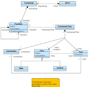
Unlike TDC Structure, CATIA does not allow these data to be exported in XML format. We have thus defined an UML class diagram relating to the structure of the RFLP module. Figure 3 presents an extract of this metamodel, for the Functional part of it.
A class diagram provides a static representation of system entities, of their properties and behaviors. Any concept, and any static object, is a class in UML. Classes describe the system’s structure. These may refer to other classes to which they are linked, which contain attributes, and describe feasible behaviors. A class can be viewed as a physical or logical entity. The system structure is represented using class diagrams. Class diagrams thus allow the system to be broken down hierarchically into classes.
Comparing the concepts found in TDC Structure’s metamodel and RFLP’s class diagram (or the functional part thereof) highlights the similarities between both data structures. Thus, both these business tools can, a priori, provide the same business model. However, in the case of TDC Structure, the tool is constructed based on the metamodel, and not the other way around. As for the RFLP module, it is clearly added into CATIA and integrated with an eye for consistency with respect to the structure of the existing software. As it will be seen later, this approach has a strong bearing on how the tool is used and how one learns how to use it.
We will now describe the case study which serves as a basis for user tests of both the TDC and CATIA RFLP tools.
3. Case study scenario
3.1. Goals and resources
This paper aims to assess the usability of tools (TDC and CATIA V6 RFLP). The tests were carried out on fourteen people, and aimed to evaluate and compare Dassault Systems’©
RFLP "module" and Knowllence©’s TDC software, as it allows us to identify problems in
real-world contexts of use. Users can raise issues, take note of which functionalities are appreciated, and provide qualitative feedback.
In order to get real-world results, the evaluators of the systems must be end-users of the software. Both novices (eight students) and experts (six senior designers) were chosen to run the test, as if they were friendly to the software or not. According to [Nielsen 1993], five users are enough to raise 80% of usability problems. However, it is hard to define a number of users that is enough, as the number depends on each test. The most important thing is to call upon end-users of the software. User tests were carried out following the protocol described below, and participant impressions were collected using questionnaires. We present these points in the next section.
3.2. Protocol and questionnaire
Nielsen points out that "Users are not designers, and designers are not users". Usability is not a single, one-dimensional property of a user interface but has multiple components [Nielsen 1993]. In order to assess the relevance of these tools, we defined it using the four usual usability attributes: learnability, efficiency, user satisfaction, and error correction. The design of the tools which we assessed in this way is still in the stages of sustained improvement. It fits within the framework of our prior work.
In order to run this comparison, the same use scenario was played for each software program. Obviously, all the functionalities of each program cannot be tested. Each user is
distributed a sheet of explanations and tasks to perform. They are asked to run through the first steps of the design of an elevator using the RFLP method in a first session, and by the TDC Suite method in a second session:
- Carrying out External Functional Analysis using the Functional module of RFLP and TDC Need.
- Matching these functions to technical components using the Logical module of RFLP and TDC Structure.
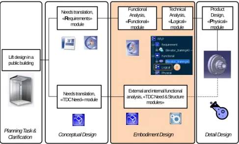
This case study is supported by a design process which describes the various technical solutions which are thought of, as well as the constraints of work in terms of time and collaboration. The protocol is described in Figure 4 below.
Figure 4. Test protocol and perimeter (in orange).
It must be pointed out that there are means today to connect TDC structure with CATIA [Iraqi et al. 2011], which is represented with a dotted line on Figure 4. The tests lasted approximately one hour for each program (i.e. two hours total).
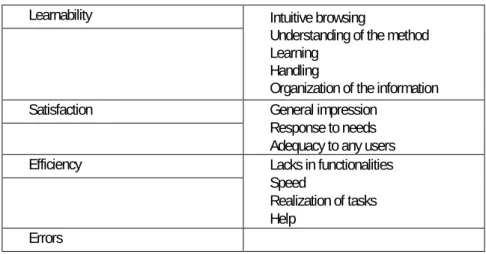
At the end of the test, in order to collect users’ opinions about the interface they had just interacted with, a questionnaire was handed to be filled in. It aimed to collect data through several indicators, and regarding the difficulties encountered. First, users were asked about their knowledge of each software program. Then, through a series of closed questions, participants were asked to choose between alternatives on a Likert-type scale. After that, they were asked to give their opinion on the graphical interface and the degree to which their needs as end-users had been met. The questions asked here were grouped in topics, following the four topics mentioned above: learnability, satisfaction, efficiency and error correction (Table 2).
Planning Task &
Clarification Conceptual Design Embodiment Design Lift design in a public building Needs translation, «Requirements» module Needs translation, «TDC Need» module Functional Analysis, «Functional» module Externaland internalfunctional analysis, «TDC Need & Structure
modules» Detail Design Technical Analysis, «Logical» module Product Design, «Physical» module
Learnability Intuitive browsing
Understanding of the method Learning
Handling
Organization of the information Satisfaction General impression
Response to needs Adequacy to any users Efficiency Lacks in functionalities
Speed
Realization of tasks Help
Errors
Table 2. Questionnaire topics.
We now present and interpret the results of the user tests.
4. Results
4.1. Presentation of results
An index is created to assess the knowledge of users concerning each of the tools. The values are weighed, so as to provide a quantitative measure of the level of knowledge of the tools tested, as shown in Table 3.
Level of
knowledge Expert Good Medium Bad None Weight 1 0.75 0.5 0.25 0
Table 3. Weight values for each of the levels of knowledge.
The knowledge index K is calculated for each tool.
With j=[0 ; 0,25 ; 0,5 ; 0,75 ; 1] nj=number of votes for level j
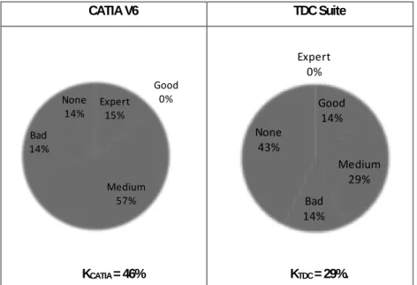
Detailed results are reported in Figure 5 below. The CATIA tool is the one which is best known a priori (46 percent vs 29 percent). This is probably due to the context in which the tests were taken. Indeed, CATIA is the CAD software program deployed at our School of Engineering, and both teaching staff and students were used to this tool.
CATIA V6 TDC Suite
KCATIA = 46% KTDC = 29%.
Figure 5. Knowledge K index of the panel for CATIA and TDC tools.
All user responses are gathered and processed using a spreadsheet.
The responses are given on a five-point Likert scale (depending on the question: excellent/completely, good/enough, average, bad/a little, and very bad/not at all). In order to obtain numerical values, each answer is weighed between 0 and 1: 0 referred to no satisfaction at all, and 1 to maximum satisfaction. The satisfaction ratio is calculated for each of the evaluation criteria, and each of the levels is weighed by 0 ; 0,25 ; 0,5 ; 0,75 and 1, a weight of 1 (respectively 0) attributed to the “excellent/totally” level (respectively very bad/not at all). Satisfaction relative to criterion i is noted Si. Furthermore, user preferences are
established for each of the tools. To achieve this, the satisfaction ratio Si is considered for
each software program, and the corresponding percentage is calculated.
with j=[0 ; 0,25 ; 0,5 ; 0,75 ; 1]
nij=number of votes for level j of criterion i
N : total number of participants
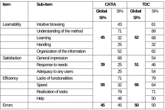
Table 4 presents a synthesis of the results obtained in this way.
Expert 15% Good 0% Medium 57% Bad 14% None 14% Expert 0% Good 14% Medium 29% Bad 14% None 43%
Item Sub-item CATIA TDC Global Si% Si% Global Si% Si% Learnability Intuitive browsing
45
43
62
61 Understanding of the method 71 89
Learning 32 68
Handling 25 32
Organization of the information 52 62 Satisfaction General impression
39
68
51
54 Response to needs 25 46 Adequacy to any users 25 54 Efficiency Lacks of functionalities
58 71 66 79 Speed 32 64 Realization of tasks 79 71 Help 48 50 Errors 45 45 50 50
Table 4. Satisfaction index for the questionnaire's items.
Grouping the results on a single graph allows us to obtain Figure 6 below.
Figure 6. Comparison of Si obtained (%) for TDC and CATIA V6, for each of the four topics
proposed by [Nielsen 1993].
We now analyze these results in order to define the ability of these two tools to support the early stages of design.
4.2. Analysis of results
This analysis allows us to compare CATIA V6 and the TDC Suite. Although it is at the moment impossible to connect a digital mock-up with the analysis carried out by the TDC suite in an industrial way, CATIA V6 provides an environment allowing this early design work to be carried out on the digital product, and in particular to connect these different parts together. In order to compare the two alternatives, we focused on the functionalities shared by these two tools: functional analysis (Functional and TDC Need modules) and technical integration (Logical and TDC Structure modules).
The study presented here shows that knowledge of the environment in the case of CATIA is superior than in the case of TDC: 46 percent for the former versus 29 percent for the latter. Results obtained by CATIA’s RFLP module are average. Although users had less knowledge of TDC, they invariably placed it in top position, be it in terms of overall satisfaction, efficiency, learnability, or errors corrected during the test.
However, users found the CATIA interface to be more attractive, which may explain why their overall impression of this tool was better (68% vs. 54% for TDC). Indeed, with its 3D platform and the possibility of inserting images, CATIA’s graphical design is more refined than TDC.
In short, this paper highlights the novelty, and perhaps the lack of maturity of CATIA’s RFLP module with respect to the TDC software suite, which was developed many years ago. Certainly, because of the numerous evolutions undergone by this module (at least two per year), the weaknesses of the product revealed by our results are likely to be corrected eventually. At the moment, as the RFLP module was only recently integrated to CATIA, it still lacks some consistency with the existing structure of the software (lack of relationships between modules, impact analysis based on functional analysis is unavailable, etc.). Results of the user tests show that this approach hinders both using the software and learning to use it. Meanwhile, TDC would benefit from interoperability with CAD software and from a more enjoyable and refined user interface in order to fully respond to user needs. Thus, the ability of tools to support the early stages of design is adequate in the case of TDC (57% satisfaction), and average in the case of RFLP (47% satisfaction). However, these early results should be analyzed in greater depth using a wider panel of participants in order to validate the design orientations. Indeed, although Nielsen assures us that five people are sufficient to detect most usability problems in a software program, a more detailed study would no doubt allow us to refine our conclusions.
5. Conclusion and future work
In this paper, we have shown that, although an integration approach to design presents numerous advantages, it is not the key to solve all issues. From their point of view, [Shyamsundar and Gadh 2002] claim that “currently, many manufacturing firms outsource the design and development of different portions of a product to different suppliers. Due to the absence of an integrated tool for collaborative product assembly design, designers currently follow an indirect approach. This makes collaboration an unorganized and inefficient activity". In contrast, we show that integrated tools such as CATIA do not yet respond sufficiently well to the needs of design in its early stages.
Nowadays, much work is being done on integrated design: one must be able to make each of the specialties involved in a project, work with one another. Even if some editors like Knowllence© have tried to make the different design tools interoperate in a logical and
effective way, CATIA V6 is currently the only software to actually propose a framework covering all steps of the design process within the RFLP methodology. One limitation of our study is that only few functionalities of CATIA V6 were tackled, mostly regarding integrated design [Tichkiewitch and Riel 2010]. We have seen that even if it supplies a single platform with a unique database, thereby reducing the time of design, some limitations can be identified compared with specialized tools.
In the end, the ideal situation would be to be able to federate specialized business tools so that they might communicate and exchange data in a fluid and consistent manner (i.e. with no data loss and no erroneous interpretation of data), not to integrate all types expertise within a single business tool. Indeed, a strong integration of all these types of expertise inevitably entails establishing a consensus regarding the points of view of the various domain experts involved in collaboration. This may hinder collaboration itself.
Acknowledgements: The authors would like to thank TDC Software, for their help in understanding the concepts of the TDC suite in general and the TDC XML schema in particular. They also point out that no financial support has been received for this study, neither from Dassault Systems©, nor from Knowllence©.
6. Bibliography
Amann, K. (2002). "Product Lifecycle Management : Empowering the Future of Business." CIMdata, Inc. Aoussat, A. (1990). La pertinence en innovation : nécessité d'une approche plurielle. LCPI. Paris,
ENSAM. PhD manuscript.
Ballu, A., Falgarone, H., Chevassus, N. and Mathieu, L. (2006). "A new Design Method based on Functions and Tolerance Specifications for Product Modelling." CIRP Annals - Manufacturing Technology 55(1): 139-142.
Berkooz, G. (2007). "Viewpoint : Bertil Turesson on PLM." International Journal of Product Lifecycle Management 2(1): 104-107.
Bézivin, J. (2006). Model Driven Engineering: An Emerging Technical Space - Generative and Transformational Techniques in Software Engineering. R. Lämmel, J. Saraiva and J. Visser, Springer Berlin / Heidelberg. 4143: 36-64.
Bouchard, C., Camous, R. and Aoussat A. (2005). "Nature and role of intermediate representations (IR) in the design process: Case studies in car design." International Journal of Vehicle Design 38(1): 1. Delphi (2010). The High Cost of Knowledge : a look at the impact of the global economy on knowledge
work, employment and organizations: 9.
Donati, T., Bricogne, M. and Eynard B. (2010). PLM platform : integrated support of the entreprise digital chain for Collaborative Product Development. 7th International Conference on Product Lifecycle Management. Bremen, Germany.
Garetti, M., Terzi, S., Bertacci, N. and Brianza, M. (2005). "Organisational change and knowledge management in PLM implementation." International Journal of Product Lifecycle Management 1(1): 43.
Geraci, A., Katki, F., McMonegal, L., Meyer, B., Lane, J., Wilson, P., Radatz, J., Yee, M., Porteous, H. and Springsteel, F. (1991). IEEE Standard Computer Dictionary : Compilation of IEEE Standard Computer Glossaries. Piscataway, NJ, USA., IEEE Press.
Iraqi, M., Kleiner, M. and Roucoules L. (2011). MODELS 2011, Model-based (Mechanical) Product Design, Wellington, New Zealand.
ISO10303-21 (1994). Industrial automation systems and integration – Product data representation and exchange – Part 21: Implementation methods: Clear text encoding of the exchange structure.
ISO10303-203 (1994). Industrial automation systems and integration : Product data representation and exchange - Part 203: Configuration controlled 3D designs of mechanical parts and assemblies. Krause, F. L., Kimura, F., Kjellberg, T. et al. (1993). "Product Modelling." CIRP Annals - Manufacturing
Technology 42(2): 695-706.
Martin, C., Djeapragache, D. and Bocquet, J.-C. (1999). Conception Intégrée. Interopérativité des méthodes : AF, QFD, AMDEC dans le cadre du projet PIRAMID. Congrès Primeca. La Plagne, Ecole Centrale - Paris Grande Voie des Vignes - 92295 Châtenay-Malabry (France).
Michard, A. (2000). XML: langage et applications, Eyrolles.
Mougenot, C. (2008). Modélisation de la phase d'exploration du processus de conception de produits, pour une créativité augmentée. Paris, Arts et Métiers ParisTech. PhD manuscript.
Nielsen, J. (1993). Usability Engineering. San Francisco, Morgan Kaufmann.
Pezeshki, C., Frame, R. T., and Humann, B. (2004). Preparing undergraduate mechanical engineering students for the global marketplace-new demands and requirements. ASEE Annual Conference Proceedings, Salt Lake City, USA.
Pratt, M. J. and Anderson, B. D. (2001). "A shape modelling applications programming interface for the STEP standard." CAD Computer Aided Design 33(7): 531-543.
Rush, C. and Roy, R. (2000). Analysis of cost estimating processes used within a concurrent engineering environment throughout a product life cycle. 7th ISPE International Conference on Concurrent Engineering. Lyon France.
Sagot, J. C., Gouin, V. and Gomes, S. (2003). "Ergonomics in product design: Safety factor." Safety Science 41(2-3): 137-154.
Schuh, G., Rozenfeld, H., Assmus, D. and Zancul, E. (2008). "Process oriented framework to support PLM implementation." Computers in Industry 59(2-3): 210-218.
Segonds, F. (2011). Contribution à l'intégration d'un environnement collaboratif en conception amont de produits. LCPI-LSIS. Paris, Arts et Métiers ParisTech. PhD manuscript.
Segonds, F., Père, C., Véron, P. and Aoussat, A. (2009). PLM and collaboration in the early stages of design, state of the art 6th International Conference Integrated Design and Production, Fes, Morocco.
Shyamsundar, N. and Gadh, R. (2002). "Collaborative virtual prototyping of product assemblies over the Internet." CAD Computer Aided Design 34(10): 755-768.
Steinberg, D., Budinsky, F., Merks, E. and Paternostro, M. (2008). EMF: Eclipse Modeling Framework, Pearson Education.
Sunnersjö, S., Cederfeldt, M., Elgh, F. and Rask, I. (2006). "A transparent design system for iterative product development." Journal of Computing and Information Science in Engineering 6(3): 300-307. Tichkiewitch, S. and Riel, A. (2010). The reasons for Integration in Design. EMIRAcle.
Tichkiewitch, S., Tollenaere, M. and Ray, P. (2007). Advances in Integrated Design and Manufacturing in Mechanical Engineering II, Springer.
Wegner, P. (1996). "Interoperability." ACM Computing Surveys 28(1): 285-287. XML eXtensible Markup Language (2011). http://www.omg.org/spec/XML/1.1/PDF.