HAL Id: tel-01913033
https://hal.archives-ouvertes.fr/tel-01913033
Submitted on 5 Nov 2018HAL is a multi-disciplinary open access archive for the deposit and dissemination of sci-entific research documents, whether they are pub-lished or not. The documents may come from teaching and research institutions in France or abroad, or from public or private research centers.
L’archive ouverte pluridisciplinaire HAL, est destinée au dépôt et à la diffusion de documents scientifiques de niveau recherche, publiés ou non, émanant des établissements d’enseignement et de recherche français ou étrangers, des laboratoires publics ou privés.
memory and performance
Alfredo Buttari
To cite this version:
Alfredo Buttari. Scalability of parallel sparse direct solvers: methods, memory and performance. Distributed, Parallel, and Cluster Computing [cs.DC]. Toulouse INP, 2018. �tel-01913033�
Scalability of parallel sparse direct solvers:
methods, memory and performance
Alfredo Buttari Chargé de Recherche, CNRS
MÉMOIRE D’HABILITATION À DIRIGER DES RECHERCHES
présenté et soutenu publiquement le 26/09/2018
Rapporteurs
Michael A. HEROUX Senior Scientist Sandia National Lab. (USA) Xiaoye Sherry LI Senior Scientist LBNL (USA)
Yves ROBERT Professeur des universités ENS-Lyon, LIP (France) Examinateurs
Patrick AMESTOY Professeur des universités Toulouse INP, IRIT (France)
Iain DUFF Senior Scientist STFC-RAL (UK)
Raymon NAMYST Professeur des universités Univ. de Bordeaux, LaBRI(France) Stéphane OPERTO Directeur de Recherche CNRS, Geoazur (France)
La solution rapide et précise de systèmes linéaires creux de grande taille est au coeur de nombreuses applications numériques issues d’une gamme très large de domaines incluant la mécanique de structure, la dynamique des fluides, la géophysique, l’imagerie médicale, la chimie. Parmi les techniques les plus couramment utilisées pour la résolution de tels problèmes, les méthodes directes, basées sur la factorisation de la matrice du système, sont généralement appréciées pour leur robustesse numérique et facilité d’utilisation. Cepen-dant, ces méthodes induisent une complexité, en termes d’opérations et de consommation de mémoire, très élevée. Les travaux présentés dans cette thèse se concentrent sur l’amélio-ration de la scalabilité des méthodes creuses directes, définie comme la capacité de traiter des problèmes de taille de plus en plus importante. Nous introduisons des algorithmes capables d’atteindre un meilleur degré de parallélisme en réduisant les communications et synchronisations afin d’améliorer la scalabilité des performances, à savoir, la capacité de réduire le temps d’exécution lorsque les ressources de calcul disponibles augmentent. Nous nous intéressons à l’utilisation de nouveaux paradigmes et outils de programma-tion parallèle permettant une implémentaprogramma-tion de ces algorithmes efficace et portable sur des supercalculateurs hétérogènes. Nous adressons la scalabilité en mémoire à l’aide de méthodes d’ordonnancement permettant de tirer profit du parallélisme sans augmenter la consommation de mémoire. Finalement, nous démontrons comment il est possible de réduire la complexité des méthodes creuses directes, en termes de nombre d’opérations et taille mémoire, grâce à l’utilisation de techniques d’approximation de rang faible. Les méthodes présentées, dont l’efficacité a été vérifiée sur des problèmes issus d’applications réelles, ont été implantées dans les plateformes logicielles MUMPS et qr_mumps distribuées sous licence libre.
Abstract
The fast and accurate solution of large size sparse systems of linear equations is at the heart of numerical applications from a very broad range of domains including structural mechanics, fluid dynamics, geophysics, medical imaging, chemistry. Among the most com-monly used techniques, direct methods, based on the factorization of the system matrix, are generally appreciated for their numerical robustness and ease of use. These advan-tages, however, come at the price of a considerable operations count and memory footprint. The work presented in this thesis is concerned with improving the scalability of sparse direct solvers, intended as the ability to solve problems of larger and larger size. More precisely, our work aims at developing solvers which are scalable in performance, memory consumption and complexity. We address performance scalability, that is the ability to reduce the execution time as more computational resources are available, introducing al-gorithms that improve parallelism by reducing communications and synchronizations. We discuss the use of novel parallel programming paradigms and tools to achieve their im-plementation in an efficient and portable way on modern, heterogeneous supercomputers. We present methods that make sparse direct solvers memory-scalable, that is, capable of taking advantage of parallelism without increasing the overall memory footprint. Finally we show how it is possible to use data sparsity to achieve an asymptotic reduction of the cost of such methods. The presented algorithms have been implemented in the freely distributed MUMPS and qr_mumps solver packages and their effectiveness assessed on real life problems from academic and industrial applications.
I am very grateful to Michael Heroux, Xiaoye Sherry Li and Yves Robert for reporting on the manuscript and to Iain Duff, Raymond Namyst and Stéphane Operto for taking part in my jury; their insightful questions and comments on the manuscript and the presentation have been extremely rewarding and encouraging for the continuation of my career.
During my career I’ve had the chance to meet and work with very talented researchers. I wish to thank all my previous colleagues from the University or Rome Tor Vergata and from the Innovative Computing Laboratory at UT Knoxville as well as my present colleagues from the APO team of the IRIT laboratory. I am very grateful to the people of the MUMPS team and, especially, to Patrick and Jean-Yves who have been throughout these years, and still are, for me a model and a great source of inspiration. The SOLHAR project has been a fantastic professional experience; I wish to thank all the members and, especially, Abdou and Emmanuel.
Special thanks go to the PhD students I’ve had the pleasure to supervise: François-Henry, Clément, Florent and Theo. Their work, talent and dedication have been of great contribution to my career.
Thanks to my boys, Roberto and Marco, who did their best to keep me from writing this manuscript but give me, every day, the motivation to improve myself. I owe the deepest gratitude to my wife, Federica, for her constant support and encouragement.
Contents v
1 Introduction 1
2 Background 7
2.1 Dense matrix factorizations . . . 7
2.1.1 Unsymmetric matrices: the Gaussian Elimination. . . 7
2.1.1.1 Accuracy of the Gaussian Elimination and pivoting . . . 8
2.1.2 Symmetric matrices: the Cholesky and LDLT factorizations. . . . 10
2.1.3 QR factorization . . . 11
2.1.3.1 Householder QR decomposition . . . 14
2.1.4 Blocked variants . . . 16
2.1.4.1 Blocked LU factorization . . . 16
2.1.4.2 Blocked QR factorization . . . 17
2.1.4.3 QR factorization with pivoting . . . 18
2.2 Sparse matrix factorizations . . . 19
2.2.1 The Cholesky multifrontal method . . . 19
2.2.2 The QR multifrontal method . . . 26
2.2.3 Additional topics . . . 31 2.2.3.1 Fill-reducing orderings. . . 31 2.2.3.2 Pivoting . . . 34 2.2.3.3 Unsymmetric methods. . . 36 2.2.3.4 Multifrontal solve . . . 36 2.2.3.5 A three-phases approach . . . 38
2.2.3.6 Sparse, direct solver packages. . . 38
2.3 Supercomputer architectures . . . 39
2.4 Runtime systems and the STF model. . . 44
3 Parallelism and performance scalability 47 3.1 Task-based multifrontal QR for manycore systems . . . 49
3.2 A hand coded task-based parallel implementation . . . 53
3.2.1 Blocking of dense matrix operations . . . 56
3.2.2 Experimental results . . . 56
3.2.2.1 Understanding the memory utilization . . . 57
3.2.2.2 The effect of tree pruning and reordering . . . 59
3.2.2.3 Absolute performance and Scaling . . . 59
3.3 Runtime-based multifrontal QR for manycore systems . . . 61
3.4 Communication Avoiding QR fronts factorizations . . . 65
3.4.2 Using Communication Avoiding factorizations within the multifrontal
method . . . 70
3.5 Multifrontal QR for heterogeneous systems . . . 75
3.5.1 Frontal matrices partitioning schemes . . . 76
3.5.2 Scheduling strategies . . . 78
3.5.3 Implementation and experimental results . . . 81
3.5.4 Combining communication-avoiding methods and GPUs . . . 83
3.6 A performance analysis approach for task-based parallelism . . . 83
3.6.1 Analysis for homogeneous multicore systems . . . 87
3.6.2 Analysis for heterogeneous systems . . . 88
4 Memory-aware 93 4.1 Memory-aware scheduling in shared-memory systems . . . 95
4.1.1 Experimental results . . . 98
4.2 Memory-aware scheduling and mapping in distributed-memory systems . 101 4.2.1 Mapping techniques . . . 102
4.2.1.1 Memory scalability of proportional mapping: an example 104 4.2.2 Memory-aware mapping algorithms. . . 104
4.2.3 Experiments . . . 106
5 Low-rank approximation techniques for sparse, direct solvers 111 5.1 Low-rank approximations . . . 111
5.1.1 Low-rank matrices . . . 111
5.1.2 Basic linear algebra operations on low-rank matrices . . . 112
5.1.3 Numerically low-rank matrices . . . 113
5.2 Low-Rank formats . . . 115
5.2.1 Block-admissibility condition . . . 116
5.2.2 Block-partitioning . . . 116
5.2.3 Nested bases . . . 117
5.2.4 A taxonomy of low-rank formats . . . 118
5.2.4.1 The Block Low-Rank format . . . 118
5.2.4.2 The H-matrix format . . . 119
5.3 BLR multifrontal . . . 120
5.3.1 Block-partitioning of fronts . . . 121
5.3.1.1 Clustering of the fully-summed variables . . . 122
5.3.1.2 Clustering of the non fully-summed variables . . . 124
5.3.2 Assembly operations . . . 126
5.3.3 BLR fronts factorization . . . 126
5.3.3.1 The FSCU and UFSC variants . . . 127
5.3.3.2 The UFCS variant with restricted pivoting . . . 128
5.3.3.3 LUAR. . . 129
5.3.3.4 Compression of the contribution block . . . 131
5.3.4 Experimental results on applications . . . 132
5.3.4.1 3D frequency-domain Full Waveform Inversion . . . 132
5.3.4.2 3D Controlled-source Electromagnetic inversion . . . 137
5.4 Complexity of the BLR multifrontal factorization . . . 140
5.4.1 FE discretization of elliptic PDEs. . . 140
5.4.2 From Hierarchical to BLR bounds . . . 142
5.4.2.2 Why this result is not suitable to compute a complexity
bound for BLR . . . 143
5.4.2.3 BLR-admissibility and properties. . . 143
5.4.3 Complexity of the dense BLR factorization . . . 146
5.4.4 From dense to sparse BLR complexity . . . 148
5.4.4.1 Complexity of the BLR variants . . . 148
5.4.5 Experimental results . . . 150
5.5 Performance and scalability . . . 154
5.5.1 Performance analysis of sequential FSCU algorithm . . . 155
5.5.2 Multithreading the BLR factorization . . . 156
5.5.2.1 Performance analysis of multithreaded FSCU algorithm . 156 5.5.2.2 Exploiting tree-based multithreading . . . 158
5.5.2.3 Right-looking vs. Left-looking . . . 159
5.5.3 BLR factorization variants. . . 160
5.5.3.1 LUAR: Low-rank Updates Accumulation and Recompres-sion . . . 160
5.5.3.2 UFCS algorithm . . . 161
5.5.4 Complete set of results . . . 163
6 Conclusions and future work 167 6.1 Future work in sparse direct methods. . . 168
A Experimental setup 191 A.1 Matrices . . . 191
Introduction
We are interested in the solution of a linear system of equations
Ax = b (1.1)
where the A matrix
• has m rows and n columns,
• is of large size, i.e., has millions of rows and/or columns,
• is sparse, i.e., most of its coefficients are structurally equal to zero.
In the case where m = n and A is of full rank (which we will assume in the remainder of this document, unless explicitly mentioned) Equation (1.1) admits a solution. If the matrix is overdetermined, i.e., it has more rows than columns, the linear system does not admit a solution in general because the number of constraints is higher than the number of degrees of freedom; in this case we rather seek the x vector which minimizes the 2-norm of the residual r = Ax− b:
min
x ∥Ax − b∥2. (1.2)
Such a problem is called a least-squares problem. If, instead, the matrix is underdeter-mined, i.e., has more columns than rows, the linear system admits an infinite number of solutions; in this case we seek the solution x whose norm is minimal:
min∥x∥2, Ax = b. (1.3)
Such a problem is called a least-norm problem.
One of the most used and well known definitions of a sparse matrix is attributed to James Wilkinson:
“A sparse matrix is any matrix with enough zeros that it pays to take advantage of them”.
There are three main ways to take advantage of the fact that a matrix is mostly filled up with zeros. First of all, the memory needed to store the matrix is less than the memory needed for a dense matrix of the same size because the zeros need not be stored explicitly. Second the complexity of most operations on a sparse matrix can be greatly reduced with
respect to the same operation on a dense matrix of the same size because most of the zero coefficients in the original matrix can be skipped during the computation. Finally, parallelism can be much higher than in the dense case because some operations may affect distinct subsets of the matrix nonzeros and can thus be applied concurrently.
Methods for solving Equations (1.1) (1.2) and (1.3) can be roughly grouped into two families: direct and iterative methods. Direct methods proceed by computing a factoriza-tion of the system matrix A such as the LU , LDLT or QR factorizations; the resulting
factors, which are easy and cheap to invert, are then used to compute the solution of the problem. On the other hand, iterative methods start from an initial guess solution, x0
say,and iteratively improve it until the desired solution accuracy is achieved or when a maximum number of iterations is reached, in which case the method has not converged to a satisfactory solution.
The convergence of an iterative method essentially depends on the numerical proper-ties of the matrix A, more precisely, on its conditioning which is defined by the matrix spectrum. Indeed, in some cases the solution of a linear system may require a very high number of iterations or convergence may not be reached at all. For this reason iterative solvers are often used in combination with preconditioning techniques. A preconditioner is usually defined as a matrix M ≈ A−1 which approximates the inverse of A; this is used to transform the linear system of Equation (1.1) into M Ax = M b1 where the system matrix M A has a more suitable spectrum which leads to a faster convergence. Although general purpose preconditioning methods exist such as Incomplete LU (ILU) or Sparse Approximate Inverse (SPAI), a preconditioner that is effective yet cheap to compute and apply may be hard to find and may, again, rely on the properties of the input problem. As a result, iterative methods can hardly be regarded as “black box” solvers. On the other hand, if the input problem is well conditioned or an appropriate preconditioner is available, iterative methods can achieve converge very quickly and with little memory consumption; moreover, iterative methods generally achieve very good scalability on large scale parallel computing platforms. Despite these good scalability on distributed memory platforms, iterative methods can only achieve a modest fraction of the peak performance of modern processing units. This is because of their poor arithmetic intensity (i.e., the ratio between the number of floating-point operations and the number of memory ac-cesses) which prevents the efficient use of cache memories; as a result, iterative methods are memory bound, i.e., run at the speed of the memory system which is commonly much slower than the processing unit. Moreover, for the same reason, iterative methods can make very poor use of multicore CPUs or accelerators because in these systems processing units are attached to a shared memory.
In my work I have been mostly interested in the use of direct solvers. These methods are generally regarded as very robust tools for the solution of linear systems as they are capable of computing accurate solutions for a very wide range of problems without the need for the user to have any knowledge of linear systems solvers. Another case where direct methods are often employed is where the same matrix has to be solved with multiple right-hand sides because the matrix factorization, which is the most expensive operation, only has to be computed once and its result reused for multiple, cheap, solve operations2. Furthermore, direct methods may have a very broad range of features including the computation of the Schur complement of a matrix, its determinant or its null-space. Finally, because they rely on dense matrix operations which have a very high arithmetic intensity, direct
1This is called left preconditioning but other options are possible.
2Note that there exist techniques for making iterative methods more effective in the case of multiple right-hand sides such as block methods or subspace recycling.
these advantages come at the price of a considerable resource consumption both in terms of memory and time. Moreover, sparse direct solvers usually exhibit a large and irregular workload which is difficult to distribute on parallel computers; this may severely limit the scalability, especially on large scale, distributed memory systems.
For the sake of completeness, it is important to mention that, in recent years, hy-brid solvers have known an increasing popularity thanks to their ability to combine the strengths of iterative and direct methods. Among these we can mention Domain Decom-position [7,62,83] or block-projection [65] methods. The effectiveness of these methods, which heavily rely on direct solvers, is still, to some extent, dependent on the numerical properties of the target problems, though.
This thesis is concerned with the usability of sparse, direct methods for the solution of very large scale sparse linear systems. As such, it deals with the issues related to their scalability, in a broad sense:
1. It addresses the performance scalability of sparse direct solvers on modern, heteroge-neous computing systems. These commonly include many CPU cores and , possibly, multiple accelerators such as GPUs. This requires algorithms that can achieve high levels of concurrency in order to feed all the working units. At the same time, it is important to develop data and workload partitioning schemes, as well as scheduling policies, which can make the most out of the computing performance available by taking into account the characteristics of the available processing units. From a strictly technological point of view, the choice of parallel programming models and tools plays an important role for achieving high performance and portability. These issues are the subject of Chapter3 and are also addressed in Section5.5.
2. It presents methods that aim at improving the memory scalability of a direct solver in a parallel setting. In order to achieve parallelism in direct solvers, more data is produced and processed in order to feed all the available working units. As a result, when executed in parallel, direct methods consume more memory with respect to a sequential run. In Chapter 4 we discuss techniques that allow the execution of the direct method in parallel within a prescribed memory envelope at the price of little or no loss of concurrency.
3. It investigates methods that improve how the complexity of sparse, direct solvers scales with the size of the problem. These take advantage of a property which is commonly referred to as data sparsity through the use of low-rank approximation techniques that allow for discarding redundant or unimportant data; this results in faster computations and lower memory consumption with a loss of accuracy which can be conveniently controlled through a single parameter. This subject is studied in Chapter 5.
Chapter 2 introduces the basic concepts that are necessary for a good understanding of the ensuing chapters; it also attempts at providing a concise introduction to dense and sparse matrix factorization methods and can serve a starting point for students or researchers who are willing to learn the basis of solving linear systems by means of direct methods. Chapter 6draws some conclusions from the this work and presents some future research developments.
This manuscript describes the research work that I have accomplished since receiving my PhD degree in 2006.
In 2006-2007 I joined the ICL laboratory at the University of Tennessee Knoxville as a post-doc. During that period I worked on the development of “tiled” algorithms [C13,
B3, C14,J15,C15,J16,J18,J19] that improve the scalability and performance of dense matrix factorizations by breaking down into multiple steps the operations that are heavy on communications and, therefore, difficult to parallelize efficiently. During this period I also worked on the use of mixed-precision iterative refinement techniques [J7,B4,J12,J13,
J18, C18] for the solution of linear systems of equations; under the assumption that the input problem is not too badly conditioned. These methods perform the most expensive operations (e.g., the factorization) in lower-precision arithmetic and then selectively use higher precision to recover the desired accuracy by means of iterative refinement. As a result, the solution can be achieved with high accuracy at the speed of lower-precision operations. These techniques can be equally applied to dense and sparse linear systems and to direct and iterative methods. When applied to dense, direct solvers this performance benefit comes at the price of an increased memory consumption because, although the factors are stored in single precision, a double precision copy of the original matrix must be kept in memory to perform the iterative refinement. On the other hand when applied to sparse, direct solvers they can also reduce the storage because the size of this extra copy is negligible compared to the size of the factors which are stored in single precision. For the sake of conciseness this work is not discussed in this manuscript.
Later, in 2008, I joined the INRIA Graal (currently ROMA) team at the LIP laboratory of Lyon. Here I got acquainted with sparse direct solvers and worked on the development of a parallel symbolic analysis which was integrated into the MUMPS solver.
At the end of 2008 I joined the APO team of the IRIT laboratory of Toulouse as a CNRS Chargé de Recherche (full time researcher). Since then I have devoted most of my research activity to sparse direct solvers, parallel computing and computational linear algebra. This thesis is essentially a résumé of the work I achieved during this period.
Most of this work was achieved in the context of four PhDs that I co-supervised: François-Henry Rouet (INPT-IRIT, 2009-2012) on the memory scalability of sparse direct solvers, Clément Weisbecker (INPT-IRIT, 2010-2013) and Theo Mary (UPS-IRIT, 2014-2017) on low-rank approximation techniques and Florent Lopez (UPS-IRIT, 2012-2015) on parallelism for multicore and heterogeneous systems.
The development of numerical linear algebra software has always been a central part of my research activity. This is mostly due to the fact that the need for fast, scalable and, at the same time, reliable solvers is motivated by the ever evolving and increasing requirements of large-scale numerical simulation applications. Through the development of production quality software packages it is possible to validate the effectiveness of methods and algorithms in working conditions that are hard to model theoretically and to assess their practical interest. Moreover, the free distribution of these packages allows us to reach out for collaborations with experts of large scale simulation applications, opening up opportunities for developing more research. I have contributed to the development of the MUMPS [13] sparse direct solver, and I am the principal developer of the qr_mumps [J10] one. I have also contributed, to a minor extent, to the PSBLAS [J17] sparse, iterative solver.
All the achievements of my research activity (including those that are not presented in this manuscript) result from close collaborations and exchanges with the IRIT-APO team as well as with other, external, academic and industrial partners: the ROMA, HiePACS and STORM teams of Inria, Dr Sherry Li’s team at the Lawrence Berkeley National Laboratory, the ICL laboratory at UTK, Prof Salvatore Filippone at Cranfield University (formerly at the University of Rome Tor Vergata), the Seiscope consortium, LSTC, EDF and EMGS.
2018), French-Israeli “Multicomputing” project (2008-2010), SCEBF (2014-2015), PhD (2016-2017) and SRFCP (2018-2019) TTIL projects, the contracts with Samtech (2008-2010), EDF (2010-2013) and EMGS (2014) and the MUMPS consortium (https:// mumps-consortium.org/).
Background
2.1 Dense matrix factorizations
2.1.1 Unsymmetric matrices: the Gaussian Elimination
One very well known method for computing the solution of Equation (1.1) with A being square (i.e., m = n) and non-symmetric is Gaussian Elimination. Through a number of convenient linear combinations of the rows of A and b, this method reduces A to an upper-triangular matrix U such that the solution x of the linear system can be easily computed through a backward substitution. The Gaussian elimination is equivalent to computing n− 1 linear transformations L−1i such that
L−1n−1...L−12 L−11 A = U.
Each L−1i is unit-diagonal and lower-triangular with all the coefficients below the diagonal equal to zero except for the i-th column and eliminates variable xi from the equations
i + 1...m. Setting L1L2...Ln−1 = L this process yields A = LU which is commonly known
under the name of LU factorization. With few algebraic manipulations and a few “Strokes of luck” [154] it is possible to show that L is also unit-diagonal and lower-triangular. The LU factorization can be computed using Algorithm 2.1 where with a(k)i,j we denote the coefficients of the so called trailing submatrix A(k) at step k; this algorithm costs 2/3n3
floating-point operations and may work in-place, i.e., the L and U factors may be stored in the same memory that originally holds the A matrix (this is possible because the diagonal of L is unitary and need not be stored).
Note that the loops in Algorithm 2.1 can be nested differently which gives rise to different variants on the LU factorization. The one in Algorithm 2.1 is the so-called right-looking variant because at step k of the factorization column k is reduced through the transformation L−1k which is also immediately applied to the trailing submatrix at the right of it. The dual of this approach is the left-looking variant: at step k, all the L−1k−1...L−11 transformations are applied to the k-th column which is then reduced by means of the L−1k transformation. Other variants exist such as the Crout one [63]. All these variants are numerically equivalent but differ in the data access pattern which may result in better use of the memory hierarchy or better potential for parallelism and vectorization.
Once the L and U factors are computed, the solution x of the linear system can be computed through the following two operations
{
Ly = b U x = y
Algorithm 2.1 LU factorization. 1: a(0)ij = ai,j for all i, j = 1, ..., n
2: for k = 1, ..., n do 3: for j = k, ..., n do 4: uk,j = a(kk,j−1) 5: end for 6: for i = k + 1, ..., m do 7: lik= a(ki,k−1)/uk,k 8: for j = k + 1, ..., n do 9: a(k)i,j = a(ki,j−1)− li,kuk,j
10: end for 11: end for 12: end for
which are called, respectively, forward elimination and backward substitution. These can be easily and cheaply (n2 flops each) computed with a doubly-nested loop.
2.1.1.1 Accuracy of the Gaussian Elimination and pivoting
When working in finite-precision arithmetic (as it happens on a computer) we may be concerned about the accuracy of the computed solution ˆx of Equation (1.1) because of the roundoff errors that occur during the computation. Classic backward error analysis [160] states that the forward error∥x − ˆx∥/∥x∥ can be bounded by the product of the condition number and the backward error. The condition number measures how the computed solution is sensitive to perturbations in the input data and does not depend on the used method but solely on the input data; for the solution of Equation (1.1) the condition number is κ(A) = ∥A−1∥ · ∥A∥ (see, for example, the book by Demmel [57] for further details). The backward error, instead, is a measure of the smallest perturbation of the input data such that the computed solution is the exact solution of the perturbed problem. If this quantity is small, the method is deemed backward stable. For the solution of Equation (1.1), the backward error, is thus defined by the following quantity
βAx=b= min { ϵ : (A + δA)ˆx = b + δb,
∥δA∥ ≤ ϵ∥A∥, ∥δb∥ ≤ ϵ∥b∥}.
A well known result by Rigal and Gaches [138] proves that βAx=b= ∥A∥∥ˆx∥ + ∥b∥∥r∥
where r = b− Aˆx is the so-called residual.
If Gaussian Elimination is used, and assuming δb = 0, it is possible to prove that [57] ∥δA∥∞≤ 3nu∥L∥∞· ∥U∥∞,
where u is the unit roundoff, which implies that the Gaussian Elimination is backward stable if 3nu∥L∥∞· ∥U∥∞= O(u)∥A∥∞. This result basically states that we have to keep the coefficients in L and U low in order to limit the backward error.
Let’s take this example extracted from the book of Golub and Van Loan [86] Ax = [ 0.001 1.00 1.00 2.00 ] · [ x1 x2 ] = [ 1.00 3.00 ] = b
to be solved using Gaussian Elimination on a computer using a three decimal digits floating point representation. The LU factorization yields
L = [ 1.00 1000 1.00 ] U = [ 0.001 1.00 −1000 ]
because 2.00− 1000 = −1000 in the three digits representation. As a result
L· U = [ 0.001 1.00 1.00 0.00 ] ̸= A and the computed solution is
˜ x = [ 0.00 1.00 ] ̸= true solution = [ 1.002... 0.998... ]
Note that the condition number κ(A) = 5.84 and thus the problem is well-conditioned. This poor accuracy can be explained observing that the coefficients of L and U have grown considerably with respect to those of A – a phenomenon that can be measured by the so-called growth factor
ρ(A) = | max i,j,k a (k) i,j| | max i,j ai,j| .
One way to prevent this excessive growth of the coefficients is a technique called pivoting. Various flavors of pivoting exist in the literature but they all share the idea of using permutations in the course of the factorization such that at step k the pivotal coefficient a(kk,k−1) is large enough with respect to the coefficients in the trailing submatrix. The most commonly used pivoting technique is called partial pivoting and consists in scanning the k-th column a(ki,k−1) for i = k, ..., m looking for the coefficient with the largest absolute value and then swapping the corresponding row with row k. Because of the division on line 7 of Algorithm 2.1, partial pivoting ensures that all the coefficients of L are lower than or equal to one. In this case the bound on the backward error becomes [57]
∥δA∥∞≤ 3n3uρ(A)∥A∥∞.
This bound can be overly pessimistic, not only because of the n3 term but also because
it is not possible to compute a tight bound for ρ(A); it can actually be shown that for some classes of problems the growth factor can be as big as 2n−1. In practice, however,
it is very rare to observe large growth factors and the Gaussian elimination with partial pivoting can be used with confidence.
As a result, the Gaussian Elimination with partial pivoting is described by a sequence of linear combinations interleaved with permutations
L−1n−1Pn−1...L2−1P2L−11 P1A = U. (2.1)
where each Pi only permutes two rows. Through simple algebraic manipulations this can
be rewritten as ˜
where ˜
Li = Pn−1...Pi+1LiPi+1T ...PnT−1.
We can observe that the only difference between Li and ˜Li is in the fact that the
subdiagonal nonzeros in column i are permuted and thus it is still possible to write ˜
L−1n−1... ˜L−12 L−11 = L−1 which yields
P A = LU. (2.3)
Taking pivoting into account, the LU factorization can be rewritten as in Algo-rithm2.2. Note that the P matrix is stored implicitly in the p array of integers, whereas L and U are stored in the memory that originally contained matrix A. This algorithm performs exactly the same number of operations as Algorithm 2.1because permutations only involve memory copies; nonetheless the use of pivoting degrades performance and limits parallelism. Algorithm 2.2 is implemented in the _getrf21 of the LAPACK [20] library.
Algorithm 2.2 LU factorization with partial pivoting. 1: for k = 1, ..., n do
2: p(k) = argmax
i=k,...,m
(|ai,k|)
3: swap rows Ak,1:n and Ap(k),1:n 4: Ak+1:m,k = Ak+1:m,k/ak,k
5: Ak+1:m,k+1:n= Ak+1:m,k+1:n− Ak+1:m,k∗ Ak,k+1:n
6: end for
Gaussian Elimination with partial pivoting applied to the matrix of the example above yields P = [ 0 1 1 0 ] L = [ 1.00 0.01 1.00 ] U = [ 1.00 2.00 1.00 ] resulting in PT · L · U = [ 0.01 1.02 1.00 2.00 ] x = [ 1.00 0.996 ]
which is a much more accurate solution with respect to the case where pivoting is not used.
2.1.2 Symmetric matrices: the Cholesky and LDLT factorizations
A matrix is symmetric positive definite if and only if A = AT and xTAx > 0 for all x̸= 0.
For such matrices the following proposition can be proved:
Proposition 2.1— A is symmetric positive definite if and only if there is a unique lower triangular nonsingular matrix L with positive diagonal entries such tat A = LLT.
1
The underscore has to be replaced be d, s for computations in real, double and single precision, respectively, and with z, c for computations in complex, double and single precision, respectively.
We refer the reader to any classic linear algebra textbook (like the one by Demmel [57] or Golub and Van Loan [86]) for a proof. The factorization A = LLT is called the Cholesky
factorization and can be computed as in Algorithm 2.3 implemented in the LAPACK _potf2 routine. This algorithm
• costs n3/3 floating point operations which is half as much as the LU factorization;
• does not require pivoting because it is backward stable due to the positive definite-ness property;
• represents the cheapest way to verify whether A is positive definite because otherwise it would break down trying to compute the square root of a negative coefficient or by making a division by zero.
Algorithm 2.3 Cholesky factorization. 1: for k = 1, ..., n do
2: ai,i = √ai,i
3: for i = k + 1, ..., n do 4: ai,k = ai,k/ak,k
5: for j = k + 1, ..., i do 6: ai,j = ai,j− ai,kaj,k
7: end for 8: end for 9: end for
When the matrix A is indefinite, the Cholesky factorization cannot be used because it leads to an unstable computation due to an excessive element growth. Obviously, the partial pivoting technique described above can be used to stabilize (at least in practice) the method but this would destroy the symmetry and thus preclude the possibility to achieve the factorization in n3/3 flops. On the other hand, using symmetric permutations
such that P APT = LLT does not always lead to a stable computation (think of the case
where all the diagonal elements of A are small). For such matrices, the most commonly used technique consists in using a factorization of the form P APT = LDLT where L is
lower-triangular and unit-diagonal and D is a block-diagonal matrix with blocks of size 1× 1 or 2 × 2. One pivoting technique to compute such a factorization was proposed by Bunch and Kaufman [44] and, at each step of the factorization, only involves searching in two columns of the trailing submatrix; this method can be proved to be as stable as the LU factorization with complete pivoting. The LDLT factorization with the Bunch-Kaufman
pivoting is implemented in the LAPACK _sytf2 routine. 2.1.3 QR factorization
This method decomposes the input matrix A ∈ Rm×n, assumed to be of full rank, into
the product of a square, orthogonal matrix Q ∈ Rm×m and an upper triangular matrix
R∈ Rn×n.
Theorem 2.1 Björck [36, Theorem 1.3.1].— Let A∈ Rm×n, m≥ n. Then there is
an orthogonal matrix Q∈ Rm×m such that
A = Q [ R 0 ] , (2.4)
where R is upper triangular with nonnegative diagonal elements. The decomposi-tion (2.4) is called the QR decomposition of A, and the matrix R will be called the R-factor of A.
The columns of the Q matrix can be split in two groups
Q = [Q1Q2] (2.5)
where Q1 ∈ Rm×nis an orthogonal basis for the range of A,R(A) and Q2∈ Rm×(m−n)
is an orthogonal basis for the kernel of AT,N (AT).
The QR decomposition can be used to solve square linear system of equations
Ax = b, with A∈ Rn×n, (2.6)
as the solution x can be computed through the following three steps
A = QR z = QTb x = R−1z (2.7)
where, first, the QR decomposition is computed (e.g., using one of the methods described below), an intermediate result is computed trough a simple matrix-vector product and, finally, solution x is computed through a triangular system solve. As we will explain the next two sections, the QR decomposition is commonly unattractive in practice for solving square systems mostly due to its excessive cost when compared to other available techniques, despite its desirable numerical properties.
The QR decomposition is instead much more commonly used for solving linear systems where A is overdetemined, i.e. where there are more equations than unknowns. In such cases, unless the right-hand side b is in the range of A, the system admits no solution; it is possible, though, to compute a vector x such that Ax is as close as possible to b, or, equivalently, such that the residual ∥Ax − b∥2 is minimized as in Equation (1.2).
Such a problem is called a least-squares problem and commonly arises in a large variety of applications such as statistics, photogrammetry, geodetics and signal processing. One typical example is given by linear regression where a linear model, say f (x, y) = α+βx+γy has to be fit to a number of observations subject to errors (fi, xi, yi), i = 1, ..., m. This
leads to the overdetermined system
1 x1 y1 1 x2 y2 .. . ... ... 1 xm ym α β γ = f1 f2 .. . fm .
Assuming the QR decomposition of A in Equation (2.4) has been computed and QTb = [ QT1 QT2 ] b = [ c d ] we have ∥Ax − b∥2 2 =∥QTAx− QTb∥22 =∥Rx − c∥22+∥d∥22. (2.8)
This quantity is minimized if Rx = c where x can be found with a simple triangular system solve. This is equivalent to saying that Ax = Q1QT1b and thus solving
Equa-tion (1.2) amounts to finding the vector x such that Ax is the orthogonal projection of b over the range of A, as shown in Figure 2.1. Also note that r = Q2QT2b and thus r is the
projection of b on the null space of AT, N (A).
Figure 2.1: Solution of a least-squares problem.
Another commonly used technique for the solution of the least-squares problem is the Normal Equations method. Because the residual r is in N (AT)
AT(Ax− b) = 0
and, thus, the solution x to Equation (1.2) can be found solving the linear system ATAx = ATb. Because ATA is Symmetric Positive Definite (assuming A has full rank), this can be achieved through the Cholesky factorization. Nonetheless, the method based on the QR factorization is often preferred because the conditioning of ATA is equal to the
square of the conditioning of A, which may lead to excessive error propagation.
The QR factorization is also commonly used to solve underdetermined systems, i.e., with more unknowns than equations, which admit infinite solutions. In such cases the desired solution is the one with minimum 2-norm:
min∥x∥2, Ax = b. (2.9)
The solution of this problem can be achieved by computing the QR factorization of AT [Q1Q2] [ R 0 ] = AT
where Q1 ∈ Rn×m and Q2∈ Rn×(n−m). Then
Ax = RTQTx = [RT0] [ z1 z2 ] = b
and the minimum 2-norm solution follows by setting z2 = 0. Note that Q2is an
orthog-onal basis for N (A) and, thus, the minimum 2-norm solution is computed by removing for any admissible solution ˜x all of its components in N (A).
2.1.3.1 Householder QR decomposition
The QR decomposition of a matrix can be computed in different ways; the use of Givens Rotations [84], Householder reflections [102] or the Gram-Schmidt orthogonalization [142] are among the most commonly used and best known ones. We will not cover here the use of Givens Rotations, Gram-Schmidt orthogonalization and their variants and refer, instead, the reader to classic linear algebra textbooks such as Golub et al. [86] or Björck [36] for an exhaustive discussion of such methods. We focus, instead, on the QR factorization based on Householder reflections which has become the most commonly used method especially because of the availability of algorithms capable of achieving very high performance on processors equipped with memory hierarchies.
For a given a vector u, a Householder Reflection is defined as
H = I− 2uu
T
uTu (2.10)
and u is commonly referred to as Householder vector. It is easy to verify that H is symmetric and orthogonal. Because Pu = uu
T
uTu is a projector over the space of u, Hx can
be regarded as the reflection of a vector x on the hyperplane that has normal vector u. This is depicted in Figure2.2(left).
Figure 2.2: Householder reflection
The Householder reflection can be defined in such a way that Hx has all zero coefficients except the first, which means to say that Hx =±∥x∥2e1 where e1 is the first unit vector.
This can be achieved if Hx is the reflection of x on the hyperplane that bisects the angle between x and±∥x∥2e1, as illustrated in Figure2.2(right). This hyperplane is orthogonal
to the difference of these two vectors x∓ ∥x∥2e1 which can thus be used to construct the
vector
u = x∓ ∥x∥2e1. (2.11)
Note that, if, for example, x is close to a multiple of e1, then∥x∥2 ≈ x(1) which may
lead to a dangerous cancellation in Equation (2.11); to avoid this problem u is commonly chosen as
In practice, it is very convenient to scale u in such a way that its first coefficient is equal to 1 (more on this will be said later). Assuming v = u/u1, through some simple
manipulations, the Householder transformation H is defined as
H = I− τvvT, where τ = (sign(x1)x1+∥x∥2) ∥x∥2
. (2.13)
Note that the matrix H is never explicitly built neither to store, nor to apply the Householder transformation; the storage is done implicitly by means of v and τ and the transformation can be applied to an entire matrix A∈ Rm×nin 4mn flops like this
HA = (I− τvvT)A = A− τv(vTA) (2.14)
The Householder reflection can be computed and applied as described above using, respectively, the _larfg and _larf routines in the LAPACK[20] library.
A sequence of Householder transformations can be used to zero-out all the coefficients below the diagonal of a dense matrix to compute its QR factorization:
HnHn−1...H2H1A = R, where HnHn−1...H2H1 = QT.
Each transformation Hk annihilates all the coefficients below the diagonal of column
k and modifies all the coefficients in the trailing submatrix Ak:m,k+1:n. The total cost of
this algorithm is 2n2(m− n/3). The Q matrix is implicitly represented by means of the
vk vectors and the τk coefficients. One extra array has to be allocated to store the τk
coefficients, whereas the vk vectors can be stored inside matrix A in the same memory as
the zeroed-out coefficients; this is possible because the vk have been scaled as described above and thus the 1 coefficients along the diagonal must not be explicitly stored. The LAPACK _geqr2 routine implements this method which is reported in Algorithm2.4. In this algorithm, line 2 computes the rk,k coefficient equal to∥Ak:m,k∥2 and the v reflector
and the τ coefficient as in Equations (2.12)(2.13); these are stored, respectively, in ak,k, Ak+1:m,k (the first coefficient of v being equal to one is not stored explicitly) and tk. This
transformation is then applied to the trailing submatrix through the operation on line 4
where the ak,k coefficient is assumed to be one. Algorithm 2.4 Householder QR factorization.
1: for k = 1, ..., n do 2: Ak:m,k, tk= house(Ak:m,k) 3: for j = k + 1, ..., n do 4: Ak:m,k+1:n= (I− tkAk:m,kATk:m,k)Ak:m,k+1:n 5: end for 6: end for
The following results define the stability of the QR factorization.
Theorem 2.2 Björck [36, Remark 2.4.2].— Let ¯R denote the computed R. It can be shown that there exists an exactly orthogonal matrix ¯Q (not the computed Q) such that
A + E = ¯Q ¯R, ∥E∥F ≤ c1u∥A∥F,
where the error constant c1 = c1(m, n) is a polynomial in m and n, ∥ · ∥F denotes the
In other words, the Householder QR factorization is normwise backward stable. The use of a QR factorization by means of a sequence of orthogonal transformations to solve least-squares problems was introduced by Golub [85]; this method is also proven to be backward stable:
Theorem 2.3 Björck [36, Remark 2.4.8].— Golub’s method for solving the standard least squares problem is normwise backward stable. The computed solution ˆx can be shown to be the exact solution of a slightly perturbed least squares problem
min
x ∥(A + δA)x − (b + δb)∥2,
where the perturbations satisfy the bounds
∥δA∥2 ≤ cun1/2∥A∥2, ∥δb∥2 ≤ cu∥b∥2
and c = (6m− 3n + 41)n.
Despite these very favorable numerical properties, the QR factorization is rarely pre-ferred to the Gaussian Elimination (or LU factorization) with Partial Pivoting (GEPP) for the solution of square systems because its cost is twice the cost of GEPP and because partial pivoting is considered stable in most practical cases.
2.1.4 Blocked variants
The above discussed factorization algorithms, commonly referred to as point factorizations, are actually never directly used in practice because they can only achieve a modest fraction of the peak performance of a modern processor. This is due to the fact that most of the computations, which are done in the application of elementary transformations to the trailing submatrix as line 5 of Algorithm 2.2, are based on Level-2 (i.e., matrix-vector) Basic Linear Algebra Subroutines (BLAS) operations and thus limited by the speed of the memory rather than the speed of the processor. In order to overcome this limitation and considerably improve the performance of dense matrix factorizations on modern computers equipped with memory hierarchies, blocking techniques are commonly employed: these consist in accumulating multiple elementary transformations and applying them at once by means of Level-3 BLAS operations. The resulting factorization algorithms are commonly referred to as blocked factorizations.
2.1.4.1 Blocked LU factorization
Assume a square matrix A is partitioned as such
A =
[
A1,1 A1,2
A2,1 A2,2
]
where A1,1and A2,2are square submatrices of size b≪ n and n−b, respectively. Executing the first b iterations of the outer loop in Algorithm2.2leads us to the following situation
P1..bA = [ L1,1 0 ˆ L2,1 I ] [ U1,1 U1,2 0 A˜2,2 ] (2.15)
where P1..b = Pb· · · P1 and ˜A2,2 is the so-called Schur complement. Computing the
re-maining n− b iterations amounts to computing Pb+1..n−1A˜2,2 = L2,2U2,2 which yields the complete LU factorization P A = [ L1,1 0 L2,1 L2,2 ] [ U1,1 U1,2 0 U2,2 ] where P = Pb+1..n−1P1..b and L2,1= Pb+1..n−1Lˆ2,1.
Note that we could get to the same situation as in Equation (2.15) trough the following steps P1..b [ A1,1 A2,1 ] = [ L1,1 ˆ L2,1 ] U1,1 (2.16a) [ ˆ A1,2 ˆ A2,2 ] = P1..b [ A1,2 A2,2 ] (2.16b) U1,2 = L−11,1Aˆ1,2 (2.16c) ˜ A2,2 = ˆA2,2− ˆL2,1U1,2 (2.16d)
Step (2.16a) is referred to as the panel factorization or panel reduction and can be achieved running Algorithm 2.2 on [AT
1,1AT2,1]T, step (2.16b) consists in simple row permutations,
step (2.16c) is a triangular system solve with multiple right-hand sides and, finally, step (2.16d) is a rank−b update or, simply a matrix-matrix product; these last three steps are commonly called trailing submatrix update.
The rest of the factorization can be achieved by applying recursively the same par-titioning and steps on ˜A2,2. The main advantage of this approach with respect to the
point LU factorization of Algorithm2.2is that, if b≪ n, the vast majority of the floating operations are done in steps (2.16c)(2.16d) which are Level-3 BLAS matrix-matrix op-erations; these can run very close to the peak performance of a processor thanks to the favorable ratio between computations and memory accesses. The blocked LU factorization is implemented in the _getrf LAPACK routine.
This blocking technique can be applied to the Cholesky factorization in a straight-forward way and, although more difficult, it can also be applied to the LDLT
factoriza-tion; the Cholesky and LDLT blocked factorizations are implemented, respectively, in the
_potrf and _sytrf LAPACK routines. 2.1.4.2 Blocked QR factorization
Blocking is more complex for the Householder QR factorization because it is not easy to accumulate elementary transformations. Schreiber et al. [143] proposed a way of accu-mulating multiple Householder transformations and applying them at once by means of Level-3 BLAS operations.
Theorem 2.4 Compact WY representation (Adapted form Schreiber et al. [143]).— Let Q = H1...Hk−1Hk, with Hi∈ Rm×man Householder transformation defined
as in Equation (2.13) and k≤ m. Then, there exist an upper triangular matrix T ∈ Rk×k
and a matrix V ∈ Rm×k such that
Proof. The proof is by induction on k. The case k = 0 is straightforward. Now assume that a matrix Qk = H1...Hk−1Hk has a compact WY representation Qk = I + VkTkVkT
and consider
Qk+1 = QkHk+1 = Qk(I− τk+1vk+1vk+1T ).
Then a compact WY representation for Qk+1 is given by Qk+1 = I + Vk+1Tk+1Vk+1T
where Tk+1= [ Tk −τk+1TkVkTvk+1 0 −τk+1 ] , Vk+1 = [ Vk vk+1 ] (2.17) which concludes the proof.
Using this technique, matrix A can be logically split into⌈n/b⌉ panels (block-columns) of size b and the QR factorization achieved in the same number of steps where, at step k, panel k is factorized using the _geqr2 routine, the corresponding T matrix is built, as in Equation (2.17) using the _larft routine and then the set of b transformations is applied at once to the trailing submatrix through the _larfb routine. This last oper-ation/routine is responsible for most of the flops in the QR factorization: because it is based on matrix-matrix operations it can achieve a considerable fraction of the processor’s peak performance. This method is implemented in the LAPACK _geqrf routine which uses an implicitly defined blocking size b and discards the T matrices computed for each panel. More recently, the _geqrt routine has been introduced in LAPACK which employs the same algorithm but takes the block size b as an additional argument and returns the computed T matrices.
2.1.4.3 QR factorization with pivoting
In case the A matrix is rank deficient, the R factor resulting from the QR factorization will have zeros on the diagonal on those columns that are linearly dependent on previously eliminated ones. This result, however, cannot be used for solving a linear system because the triangular system solve involving R will fail with divisions by zero. In such cases, a QR factorization with column pivoting [45] can be used: at each step k, the column whose norm is the highest is brought in position k with a column swap. This technique yields the factorization QTAΠ = [ ] R1,1 R1,2 r 0 R2,2 m− r r n− r
In exact arithmetic R2,2= 0 and r is the rank of A; in finite arithmetic R2,2 is considered
to be zero if it is small enough, for example, if its 2-norm or it left-topmost coefficient (R2,2)1,1 are smaller than a prescribed threshold. Assuming x is split in two parts, x1
containing the first r elements and x2 containing the remaining n− r ones, the solution of the rank deficient least squares problem can be computed as explained for Equation (2.8) by setting x2 = 0.
Computing the column-pivoted QR factorization requires the norms of all the columns in the trailing submatrix at each step. Instead of computing these values at each step, it is possible to compute them once before the factorization and only update them after each Householder elimination. Let c be a vector of size n containing the square of the 2-norms
of the column of A, ci = ∥A:,i∥22, and assume one Householder reflection is applied to A
in order to annihilate all the coefficients in the first column except the first. Because this is a unitary transformation, the c vector can be updated to store the square 2-norms of the columns of the trailing submatrix A(1) with the simple operation c
i = ci− r1,i2 . Note
that, because all the column norms have to be updated at each step, blocking techniques cannot be used to their full extent and thus, in the column-pivoted QR factorization a large part of operations is done in Level-2 BLAS routines.
2.2 Sparse matrix factorizations
The factorization of a sparse matrix is considerably more complex than its dense coun-terpart because special care must be taken to the sparsity structure of the matrix in order to avoid useless computations on zero coefficients. In this document we will assume that square matrices are structurally symmetric; this greatly simplifies the handling of dependencies between computations and implies a number of other favorable structural properties. Note that, in the case where the structure of the matrix is not symmetric, it is possible to “symmetrize” it by explicitly storing zero coefficients in order to make sure that if ai,j if present then also is aj,i. Of course, if the structure of the original matrix is strongly unsymmetric, many zero coefficients have to be added to the structure in order to symmetrize it which may result in an excessive memory and computational overhead; for these cases dedicated unsymmetric factorization methods can be employed and we will briefly mention them.
2.2.1 The Cholesky multifrontal method
Consider a symmetric, positive definite matrix A with the sparsity structure shown in Figure2.3(left) and suppose we execute Algorithm2.3on it. The structure of the resulting L factor is reported in Figure 2.3(right). Two interesting observations can be made:
1. Eliminating one variable through one iteration of the outer loop in the Cholesky algorithm does not necessarily imply updating all the coefficients in the trailing submatrix. For example, when the first iteration is executed, only the coefficients in columns 1 (obviously), 4 and 9 are modified; this is because for all the other columns j, lj,1 is equal to zero and, therefore, the update operation ai,j = ai,j− lj,1li,1 has no
effect.
2. Some of the coefficients that were zero in A have been turned into nonzero by the factorization; for example when the second iteration of the Cholesky factorization is executed a4,3 becomes nonzero due to the update a4,3 = a4,3− l4,2l3,2. As a result
the structure of L + LT is denser than that of A; this phenomenon is referred to as
fill-in. Because of fill-in the cost of a sparse factorization can be very high, both in terms of memory and time, even for very sparse matrices.
This two properties can be more formally stated by Propositions2.2 and2.3.
Proposition 2.2— For j > k the numerical values of column j depend on column k, denoted k → j, if and only if lj,k ̸= 0.
By saying that column j depends on column k we mean that eliminating variable k updates the numerical values of column j. This implies that the second term on the
1 2 3 4 5 6 7 8 9 1 a a a 2 a a a a 3 a a a 4 a a a a 5 a a a 6 a a a 7 a a a a a 8 a a a a 9 a a a a 1 2 3 4 5 6 7 8 9 1 l 2 l 3 l l 4 l l l l 5 l 6 l l 7 l l l l 8 l l l l 9 l l l l l l
Figure 2.3: The structure of a symmetric sparse matrix A and of the associated Cholesky factor L. The fill-in in L is represented with underlined letters.
right-hand side in line 6 of Algorithm 2.3 is nonzero which is true if and only if lj,k is nonzero.
Proposition 2.3— Let be i > j > k. If column j and column i depend on k then column i depends on column j.
Proof. The fact that both columns j and i depend on column k implies that lj,k ̸= 0 and li,k ̸= 0. Therefore, li,j will be nonzero as a result of the update on line6of Algorithm2.3.
As a consequence of Proposition 2.3 it is easy to see that, a fill-in coefficient li,j is created if ai,j = 0 and li,k and lj,k are nonzero for some k < i, j.
The canonical tools for formalizing the theory of sparse matrix factorizations and characterizing the fill-in are graphs: a sparse matrix A can be represented by the graph G(A) = (V, E) whose vertex set V = {1, 2, ..., n} includes the unknowns of A and edge set E = {(i, j) ∀ ai,j ̸= 0} includes an edge for each nonzero coefficient of A. In our case, the
symmetry of the matrix implies that if (i, j) is in E then also (j, i) is and therefore we will only represent one of these edges and the graph will be undirected. The graphG(A) is also commonly called the adjacency graph of A. Figure2.4 shows, on the top-left , the adjacency graph for the matrix in Figure2.3.
It is possible to use the adjacency graph to model the factorization of a sparse matrix. Specifically we can build a sequence of graphs G(A) = G0(A),G1(A), ...,Gn−1(A), called
elimination graphs, such thatGk(A) is the adjacency graph of the trailing submatrix after elimination of variables 1, 2, ..., k. Elimination graph Gk(A) is built from Gk−1(A) by
removing node k as well as all its incident edges and by updating the connectivity of the remaining nodes. By Proposition 2.3, for any two nodes i and j neighbors of k we have to add an edge connecting them if it does not exist already; this models the occurrence of a new fill-in coefficient. In other words, upon elimination of node k, a clique is added to the graph which includes all the neighbors of k. Algorithm2.5 shows the elimination graphs process and Figure2.4shows the elimination graphs for the matrix in Figure 2.3. The elimination graphs process suggests that, if inG(A) there is a path i, k1, k2, ..., kp, j
with ks < min(i, j) ∀s, then li,j must necessarily be nonzero. This is because whenever
one of the ks nodes is eliminated, its two neighbors along the path become connected (if
they weren’t already); therefore, when the last of these ks nodes is eliminated i and j
become connected. This intuition leads to one very well known result by Rose, Tarjan and Lueker [139]:
G(A) 1 2 3 4 5 6 7 8 9 G1(A) 2 3 4 5 6 7 8 9 G2(A) 3 4 5 6 7 8 9 G3(A) 4 5 6 7 8 9 G4(A) 5 6 7 8 9 G5(A) 6 7 8 9 G6(A) 7 8 9 G7(A) 8 9 Gf(A) 1 2 3 4 5 6 7 8 9
Figure 2.4: Adjacency graph (top-left), eliminations graphs and filled graph (bottom-right) of matrix A in Figure 2.3.
Theorem 2.5 (Rose et al. [139]).— Let i > j. Then li,j ̸= 0 if and only if there exist
a path
j, k1, k2, ..., kp, i
in G(A) such that ks< min(i, j).
although the “if” part of this theorem can easily be understood following the idea described above, the proof of the “only if” part is more complex and we refer the reader to the original paper for its description.
Algorithm 2.5 Elimination graphs process. G0(A)← G(A) = (V, E)
for k = 1, ..., n− 1 do V ← V − {k}
E ← E − {(k, l) : l ∈ adj(k)} ∪ {(i, j) : i ∈ adj(k) and j ∈ adj(k)} Gk← (V, E)
end for
The graph Gf(A) obtained by adding to G(A) all the edges associated with fill-in coefficients is called filled graph and corresponds to the adjacency graph of L + LT. For
the matrix in Figure 2.3 the filled graph is reported in the bottom-right of Figure 2.4. The directed filled graph −→Gf(A) is obtained from the filled graph assuming that an edge
(i, j) is directed from i to j if j > i. This graph cannot have cycles, for which reason it is called a Directed Acyclic Graph (DAG).
Note that −→Gf(A) represents the dependencies among the columns of the matrix as defined in Proposition 2.2 and its transitive closure states whether a variable can be eliminated before another. Note that, in order to establish a dependency between columns i and j, we are only interested in knowing whether there exist a path in−→Gf(A) connecting
nodes i and j; therefore the directed filled graph can be simplified by keeping the longest path connecting i and j and discarding all the others. This amounts to computing the transitive reduction of −→Gf(A) which we call T (A). Note that T (A) is equivalent to the
directed graph associated with the matrix obtained by removing from L all the coefficients below the diagonal except the first which can easily be seen using Proposition2.3. Assume that li,k ̸= 0 and lj,k ̸= 0 with i > j > k; because we know that li,j must necessarily be
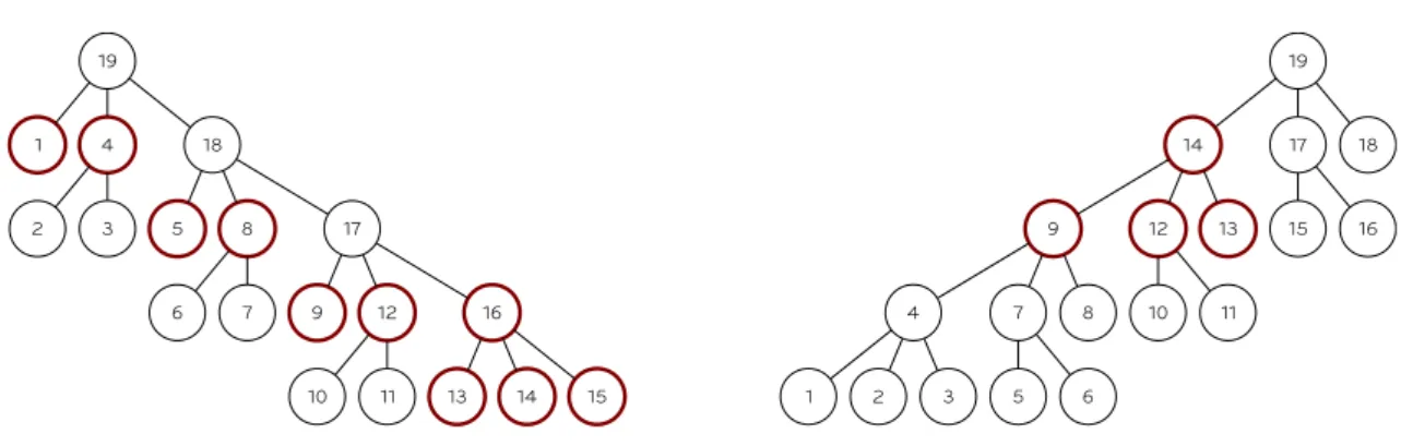
nonzero, we can suppress li,k because the dependency k → i is indirectly represented by the chain of dependencies k→ j → i. Schreiber [144] shows that, if the matrix A is not reducible, this graph is an ordered tree with root n (hence the choice of the letter T for denoting it). T (A) is the most compact way of representing all the column dependencies in the factorization of a sparse matrix and is commonly referred to as elimination tree. Definition 2.1 Elimination tree [144].— Let A be a sparse, symmetric positive definite matrix of size n with Cholesky factor L. The elimination tree is defined to be the structure with n nodes{1, 2, ..., n} such that the node p is the parent of node j if and only if
p = min{i > j | li,j ̸= 0}.
From this definition and the theory discussed above, the two following theorems can be derived.
Theorem 2.6 ([144]).— If lj,k ̸= 0 and k < j, then the node k is a descendant of j in the elimination tree.
Theorem 2.7 ([119]).— If node k is a descendant of node j in the elimination tree, then the structure of the vector [lj,k, ..., ln,kT ] is contained in the structure of [lj,j, ..., lTn,j].
Based on the theory discussed in the previous section, various sparse matrix factoriza-tion techniques can be defined. Among the most commonly used ones is the multifrontal method introduced by Duff et al. [66]. The following discussion of the multifrontal method is extracted from a 1992 paper by Liu [119].
Let A be a sparse, SPD matrix, L its Cholesky factor and i0, i1, ..., ir be the
row-subscripts of column j of L with i0 = j. We denote with T the associated elimination
tree and withTj the subtree rooted at node j.
The following two definitions lay the foundations of the multifrontal method. Definition 2.2 Subtree update matrix [119].— The j-subtree update matrix is
¯ Uj =− ∑ k∈Tj−{j} lj,k li1,k .. . lir,k [lj,kli1,k· · · lir,k] .
− → Gf(A) 1 2 3 4 5 6 7 8 9 T (A) 1 2 3 4 5 6 7 8 9 1 2 3 4 5 6 7 8 9 1 l 2 l 3 l l 4 l l l 5 l 6 l l 7 l l 8 l l l 9 l l T (A) 1 2 3 4 5 6 7 8 9
Figure 2.5: Adjacency graph (top-left), eliminations graphs and filled graph (bottom-right) of matrix A in Figure 2.3.
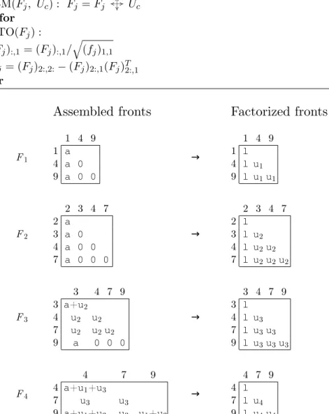
Definition 2.3 Frontal matrix [119].— The jth frontal matrix (or front) Fj for A is
defined to be Fj = aj,j aj,i1 · · · aj,ir ai1,j .. . 0 air,j + ¯Uj.
The subtree update matrix contains all the updates related to nodes that are descen-dants of j in the elimination tree; these are all the updates related to elimination steps k that modify column j either directly, if lj,k ̸= 0, or indirectly, if lj,k = 0. For this
rea-son, when Fj is computed, its first row and column are said to be fully updated (or fully summed or fully assembled) in the sense that they have received all the updates related to previous elimination steps and, therefore, correspond to the row and column j of the trailing submatrix A(k) at step k of the factorization. As a result, a single elimination
step on Fj generates column j of the factor L:
Fj = lj,j 0 · · · 0 li1,j .. . I lirj 1 0 · · · 0 0 .. . Uj 0 lj,j li1,j · · · lir,j 0 .. . I 0 (2.18)
where Uj is a Schur complement which is commonly referred to as update matrix (or contribution block). Note that the first row and column of Fj are full, which necessarily