Publisher’s version / Version de l'éditeur:
Vous avez des questions? Nous pouvons vous aider. Pour communiquer directement avec un auteur, consultez la première page de la revue dans laquelle son article a été publié afin de trouver ses coordonnées. Si vous n’arrivez pas à les repérer, communiquez avec nous à PublicationsArchive-ArchivesPublications@nrc-cnrc.gc.ca.
Questions? Contact the NRC Publications Archive team at
PublicationsArchive-ArchivesPublications@nrc-cnrc.gc.ca. If you wish to email the authors directly, please see the first page of the publication for their contact information.
https://publications-cnrc.canada.ca/fra/droits
L’accès à ce site Web et l’utilisation de son contenu sont assujettis aux conditions présentées dans le site LISEZ CES CONDITIONS ATTENTIVEMENT AVANT D’UTILISER CE SITE WEB.
Building Research Note, 1982-11
READ THESE TERMS AND CONDITIONS CAREFULLY BEFORE USING THIS WEBSITE. https://nrc-publications.canada.ca/eng/copyright
NRC Publications Archive Record / Notice des Archives des publications du CNRC :
https://nrc-publications.canada.ca/eng/view/object/?id=52e0e65b-f93d-4dda-93c2-1c42946bb099 https://publications-cnrc.canada.ca/fra/voir/objet/?id=52e0e65b-f93d-4dda-93c2-1c42946bb099
NRC Publications Archive
Archives des publications du CNRC
This publication could be one of several versions: author’s original, accepted manuscript or the publisher’s version. / La version de cette publication peut être l’une des suivantes : la version prépublication de l’auteur, la version acceptée du manuscrit ou la version de l’éditeur.
For the publisher’s version, please access the DOI link below./ Pour consulter la version de l’éditeur, utilisez le lien DOI ci-dessous.
https://doi.org/10.4224/40000516
Access and use of this website and the material on it are subject to the Terms and Conditions set forth at
HUDAC MARK XI research project: performance of solar heating
system, 1979-1980
Ser
Trn
B92
HUDAC PIARK XI RESEARCH PROJ&CT
-
PERFORMANCE OF SOLAR HEATING SYSTEM, 1979-1980 by
B.E. Sibbitt and W.E. Carscallen
ANALJ'ZED
Division of Building Research, National Research Council Canada
- !
I 1 !HWAC WiRK XX RESEARCH PROJECT - PERFORMANCE OF SOLAR HEATING SYSTFM, 1979-1980
B.E. S i b b i t t and W.E. Catscallen
The Division of Building Research and the Housing and Urban Development AssocfatFon of Canada {HUPAC) are cooperating on a p r o j e c t t o
study energy ase in four detached houses located in a h o u s i n g development near Ottawa. One of the objectives of t h e p r o j e c t was to evaluate the performance of the air-based solar heating system installed on Hause 3,
t o compare its cnerw s a v i n g potential with that of other energy s a v i n g measures. The solar system w a s monitored in some d e t a i l through the
1979-80 heating season. This note describes t h e operational experience w i t h the solar system and presents an evaluation of i t s performance,
including t h e net energy savings and the effect of the system on b u i l d i n g performance.
BUILDING AND SYSTEM DESCRIPTION
The layout of the t e s t houses is shown in Figure 1. House 1 (HI) was hilt t o t h e insulation requirements of the 1975 Ontario
Building Code. Houses HZ, H 3 and H4 were constructed with higher levels of insulatfan: above grade walls, R = 3.5 (20) ; ceiling, R = 5.6 (32) ; and basement walls, R = 1 . 3 (7.5) t o the footing*. These three houses a l s o feature a w e l l sealed polyethylene airjvapour barrier, triple-glazed casement windows, and i n s u l a t e d steel doors w l t h storm doors. A l l four houses have the same shape, are o r i e n t e d in the same d i r e c t i o n and have 120
II?
of l i v i n g space on two floors p l u s a f u l l basement.The solar system L n s t a l l e d i n H 3 was one of the few pre-
engineered systems available i n 1976. A pre-engLneered system was chosen over a custom-designed system I n the expectation t h a t such a system would be easier to c o d s s i o n and w o u l d have fewer operational d i f f i c u l t i e s . This expectation was n o t met for a nlrmber of reasons, to be described in the rest of t h i s note,
The s o l a r s y s t e m 2s shown in Figure 2 and described in Table 1. An array af 2 1 air-heatfng solar collectors were mounted on the roof, whfch s l o p e s
69'
to the h o r i z o n t a l and faces 24O east of south. Thec o l l e c t o r array is connected by ductwork t o t h e solar collection f a n and
the pebble-bed heat storage unit located under the attached garage. An
air-to-water heat exchanger for sesvlce water preheating is l o c a t e d in the collection loop. An auxfliary electric furnace, furnace fan, dampers, a two-stage t h e m s t a t and a controller complete the heating *Resistance (R) is g i v e n in S3[ Units (&*K/w) with British U n i t s
system. The controller a l l o w s t h e system to operate in one of several modes by s e l e c t i v e l y powering the two system f a n s and the three motorized dampers.
SOLAR SYSTEM OPERATION
Throughout the heating season, manual damper 1 remains open and manual damper 2 remains c l o s e d , petrmltting use of the heat storage
subsystem.
Heating from Coklector
This mode is employed when solar energy is available for
c o l l e c t i o n w h i l e a demand for space heating exists. Motorized dampers MP1 and MD2 are open, MD3 is closed, and both the solar c o l l e c t i o n fan and t h e furnace f a n operate. PJr is drawn through the solar collector bg the collection fan, blown through t h e furnace to t:he living space, and
f l m s back through t h e cold a i r r e t u r n to the collectar. S t o r i n g Heat
T h l s mode is employed when solar energy is available for c o l l e c t i o n , b u t there is no demand f o r space heating. MD1 i s open and MD2 and MD3 are closed, The solar c o l l e c t i o n fan draws afr through the
c o l l e c t o r array and b l w s i t d m through the heat storage unit and back
t o the c o l l e c t o r . Heat is added t o the storage b i n in such a way that t h e upper part remains warmer than the bottom.
Reatine from Storage
This mode is employed when a space heating demand exists but s o l a r enerF=y is n e t being collected. Mf12 is open and MDl and MD3 are closed. The f u r f i a c e f a n draws air from the living space up through the
s tarage and t h e s2r h a n d l e r , and then blows the w a r n air back t o the
space. Air flow up through the storage provides the warmest air for
d e l i v e r y t o the space.
When heat from the storage is unable to maintain t h e indoor air temperature at t h e themostzt: s e t p a f n r , t h e a i r f l a w circuit remains
unchanged b u t e l e c t r i c heat ks added under the control ef the second s t z g e of the thermostat. When alr l e a v i n g the storage u n i t d r o p s below
32°C ( 9 0 " ~ ) t h e f i r s t stage of the thermostat is used to control the a d d i t i o n of e l e c t r i c a l resistance heatLng-
Continuous Fan
The storage bypass duct and motoxfzed damper MD3 were provided to permit continuous furnace f a n operation without heating.
Service Water Preheatfne
Whenever t h e solar collection fan circulates air through the
c a l l e c t a r array, hot air returning from the collector passes through an
afr-to-water heat exchanger whicb preheats service h a t water. A small pump circulates water between the preheat storage ta& and the heat
exchanger whenever solar energy fs being collected and if the storage water temperature is befm 60°C ( 1 4 0 ° F ) .
In summer, the system is only used to preheat the s e r v i c e
water. Manual damper 1 is closed and manual damper 2 is opened in order
to bypass the pebble-bed storage and t h e l i v i n g space. Whenever solar energy is available f o r collection and the temperature of water in the
preheat tank is below 60°C (1404F), air is circulated from the air
handler, through the c o l l e c t o r and back through t h e service-water preheat coil to the a i r handler.
OPERATIONAL EXPERIENCE
I n s t a l l a t i o n of the solar system by l o c a l contractors was
completed in December 1977. A m o n i t o r i n g system consisting primarily of integrating energy meters was i n s t a l l e d in the summer o f 1978 to permit monitoring of the performance of the solar system, "as installed", during
the 1978-79 heating season. Because H3 was to remain unoccupied throughout the study period, a device was d e s i g n e d to automatically impose a scheduled demand on the service hot water heatlng system of 220 L/day. This l o a d s i m l a t o r was a l s o i n s t a l l e d in t h e summer of 1978.
Over the 1938-79 heating season, the auxiliary e l e c t r i c furnace in the unoccupied solar house (H3) consumed appsox5mtely the same amount
of energy as t h e e l e c t r i c furnace in the occupied upgraded house (HZ).
The n e t reduction i n purchased space heating energy with the solar space heatlng system would, t h e r e f o r e , appear t o be small, approximately equal to t h e internal g a l a s in the occupied H2. The s o h r system, however, s u p p l t e d approximately 3.6 GJ (1.0 MWh) to the d o m e s t l c hot water system over the f i r s t heating season, and 7 - 2 GJ (2.0 MWh) over the f i r s t f u l l year of operation (October 1978
-
October 1979). The total energy saved in the f i r s t year thus appeared to be considerably less than the 50%p r e d i c t e d by t h e manufacturer.
During the spring of 1979, the solar system was examined f o r faults that d g h t explain the poor observed performance. Of several f a u l t s digcovered, the most serious was that rnotorlzed damper MD3 was
i n s t a l l e d in such a way t h a t it was never able to open or c l o s e
completely. Thus the storage unit was bypassed in the "heatlng-from- storage" mode. The household retnrn air tended to Elm past damper M D 3 , which w a s supposed to be c l o s e d , rather than through the storage unit. This i n a b i l i t y to use stored heat increased the use o f the back-up
load, It a l s o increased the storage temperature and storage losses, and thereby lowered c o l l e c t i o n e f f i c i e n c y . Unlike MD1 and m2, damper MD3 was supplied by t h e sheet metal contractor and not by t h e solar system
manufacturer.
Another serious fault, which had a significant effect on t h e house heating load, was system air leakage. Large afr leaks w e r e found in :he solar collector array, the duct cartnections to the storage bin, the collection fan, and the ducts themselves. Other f a u l t s i n c l u d e d
improper adjustment of the motorized d a m p e r s and the i n a b Z l k t y of the air
h a n d l e r fan t o supply more t h a n 75% of the d e s i g n a i r f l w rate. Each of these f a u l t s would have contributed to the poor initial performance.
During t h e summer of 1979, an attempt w a s made ta correct these f a u l t s so t h a t t h e system performance, as d e s i g n e d , m i g h t be assessed in the 1979-80 heating season. Motorized damper MD.3 was replaced with a unit similar to 'MD1 and MIE2, and a l l three were adjusted far correct operation. Although duct seams had been caulked at the time of installation, accessible seams and connections were recaulked with
s i l i c o n e sealant; t h e air handler pulleys were changed so that design air
f l o w rate was achieved i n the c o l l e c t o r r e t u r n duct. The alr tightness of the interconnectfons between collectors was judged to be a system
d e s i g n feature and was l e f t unmodified, A data logging s y s t a n was also i n s t a l l e d at this t i m e to assllst in understanding system problems.
Several system prohlems persisted throughout the 1479-80
h e a t i n g season, even a f t e r the cosrectf ons were made. S i g n i f i c a n t o v e r heating of the indoor space occurred during solar collector operation on sunny s p r i n g a n d fall days.
Another persistent problem was condensation, which appeared
r e g u l a r l y on the undersrde of the i n n e r g l a z i n g of a l l 2 1 collector p a n e l s . Moisture also collected between the inner and outer glazings of a f e w c o l l e c t a r s , indf rating ef thet f allure of the glazing s e a l or poor sealing of the pressure-equalization tube during system i n s t a l l a t i o n .
Water within the c o l l e c t o r s wlll reduce t h e service llfe a s w e l l a s the thermal performance of the units.
The s o l a r system requlred r e l a t i v e l y l i t t l e attention after i t had been p r c q e r l y c o m ~ s a i o n e d . Corrective maintenance w a s requited,
however, when the collection f a n pulley became l o o s e on i t s shaft and
a l s o when a control system relay failed.
P E R F Q W C E OF THE SOLAR HEATING SYSTEM AND HOUSE 3
The solar s y s t e m in H 3 s u p p l i e d a significant amount of energy
to the space and water h e a t i n g l o a d s durlng the 1979-80 heatfng season but it also a f f e c t e d the total amount of energy (solar plus electrical) consumed in t h e house, the rate of air exchange with the outdoors, and t h e temperature w i t h i n t h e heated space.
In examining the various aspects of W3 and salar system perfosacance, I t is useful to conpare measurements made in H3 and
HZ.
Both houses are of nearly i d e n t i c a l c o n s t r u c t i o n and both were unaccupied during the 1979-80 test year. They differ only in t h a t H2 has a central e l e c t r i c furnace rather than a solar heating system wtth an e l e c t r i c a l back-up furnace.
AZr Leakage
Air leakage caused the majority of solar system-related problems in R3 d e s p i t e the f a c t that d u c t s e a m and connections, where accessible, had been recaulked. Leakage contrfbuted to overheating of
t h e Indoor space and pressurization of t h e house, thereby increasing exfrltration through the building envelope, increasing the house heat load and reducing s a l a r system p e r f o m n c e .
M s leakage tests using the f a n pressurfzatfon m e t h o 8 s 5 (at 10 Pa) provided an indication of the relative tightness of the four houses. House 3 had a leakage s a t e of 0.135 u?
I s ,
significantly higherthan the t w o comparable upgraded houses, H2 (0.119 m3
I s )
and H3(0.120 m 3 / s ) , but lower than the s t a n d a r d house, H 1 (0.161 m3 / s ) . The
h i g h leakage rate of H3 was probably due to the following: leakage openings in t h e c o l l e c t a t a r r a p , leakage openings around the duct penetrations through the wall and ceiling air/vapour barriers, and differences in r*olrkmanship between the houses.
The solar c o l l e c t o r array generally operated below outdoor ambient pressure because of tts location on the suction s i d e of the
c o l l e c t i o n fan. Whenever t h e fan was operathng, air leaked into t h e
collector array f ram outdoors, was blown through t h e s y s tern fan and leaked from ducts into the house, pressasfztng the indoor space. The
h i g h e r indoor pressure, combined with the looser b u i l d i n g envelope, produced a significantly higher air change rate In H3 than in R2.
Tfie i n f l u e n c e of solar system operation on t h e a i r change r a t e
of W3 was measured on March 6 , 1980 using t h e C02 tracepgas decay
n ~ e b h o d . ~ With the solar c o l l e c t i o n f a n o f f , 0.23 a i r changes p e r hour (ac/h) were measured. With the c o l l e c t i o n fan operating, the rate
increased to 0.49 ac/h in t h e "storing-heat'" mode, and to 0.66 aclh in rhe "heatTn~froarcoL1,ector'- mode. The average value of a i r change f a r
H4, obtained from a series of t e s t s performed over the heating season, was 0.20 a c h . T h i s value should be representative for
H2
a s well, s i n c e H 2 and H4 had virtually identical a i r leakage characteristics.Assuming that t:he air change rates measured in March would a p p l y throughout t h e heating season, it 1 s estimated that H3 had a
seasonal average a i r change rate af 0.26 ac/h compared with an average of
0.20 a c h f o r H2. A s a result o f t h i s h i g h e r average air change rate,
the annual heating requirement of H3 is estimated to be 3 . 6 GJ (1.0 MMh)
greater than that of H2.
*
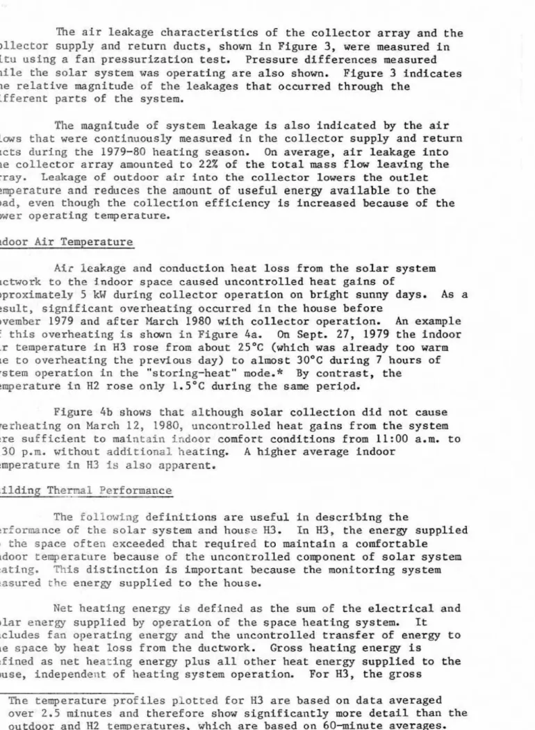
For t h e purpose of this d i s c u s s i o n , the c o l l e c t o r array is defined asThe air leakage c h a r a c t e r i s t i c s of the collector array and the
c o l l e c t o r supply and r e t u r n ducts, shown in Figure 3, were measured in
s i t u using a fan pressurization test* Pressure differences measured whlle the solar system w a s operating are a l s o shown. Figure 3 indicates
t h e r e l a t i v e magnitude o f the leakages that occurred through the different parts of the system.
The magnitude of system leakage is also i n d i c a t e d by the air
f l m s t h a t were continuaus9y measured in the collector supply and return d u c t s during the 1979-80 heating season. On average, air leakage into t h e c o l l e c t o r array amounted t o 22% of the total mass f l o w leaving the
array. Leakage of outdoor air i n t o the collector lowers the outlet temperature and reduces t h e amount of u s e f u l energy a v a i l a b l e t o the l o a d , even though the c o l l e c t i o n efficiency is increased because of the lower operating temperature.
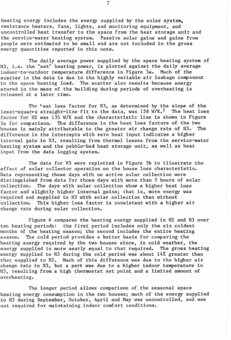
Indoor Air Temperature
A i r leakage and conduction heat loss from the solar system
ductwork to the jndoor space caused uncontrolled heat ga3ns of
approximately 5 kW during collector operation on bright sunny days. As a r e s u l t , s i g n t f i c a n t overheating occurred in the house before
November 1979 and after March 1980 with collector operation. An example
o f this overheating is s h m I n Figure 4a. On Sept. 2 7 , 1979 t h e Indoor air temperature in H3 rose f r o m about 2 5 ° C (whfch was already t o o warm
due to overheating t h e prevLous day] to almost 30°C during 7 hours of
system o p e r a t i o n in the "storing-heat" mode.* By contrast, the
temperature in HZ rose only 1 . 5 " C during t h e same period.
Figure 4b shows t h a t although solar collection d i d not cause
overheating on March 12, 2980, uncontrolLed heat gains from the system were sufficient to maintain fndoor comfort condftfons from 11:00 a.m. t o
3 : 3 0 p.m. without a d d i t i o n a l heating, A h i g h e r average indoor temperature tn
W
f s also apparent.Building Thernal Performance
The following d e f i n i t i o n s are useful in d e s c r i b i n g the
performance of t h e solar s y s t e m and housc H3. h F13, the energy supplied t o the space often exceeded t h a t required to maintah a comfortable
indoor temperature because of the uncontrolled component of solar system
h e a t i n g . Ris d i s t i n c t i o n is important because the monitorfng system
measured rhc energy s u p p l i e d to t h e house.
N e t h e a t i n g energy is defined as the sum of the electrical and solar energy s u p p l i e d by o p e r a t i o n of the space heattng system. It
includes fan operating energy and t h e uncontrolled transfer of energy to
t h e space by heat loss from t h e ductwork. Cross heating energy is d e f i n e d as net h e a ~ i n g energy plus a l l other heat energy supplied to the hause, independent of heating system operation. For H3, the gross
*
The temperature p r o f i l e s plotted far H 3 are based on d a t a averaged over 2.5 minutes and t h e r e f o r e show s i g n i f i c a n t l y more d e t a i l than theheating energy fncludes the enerjg supplied by t h e solar system, resistance heaters, fans, lights, and monitoring equipment, and
uncontrolled heat transfer t o the space from the h e a t storage unit and the service-water h e a t i n g system. Passive solar gains and g a i n s from
p e o p l e were estimated to be smalf and are n o t i n c l u d e d in t h e gross energy q u a n t i t i e s reported kn t h i s note,
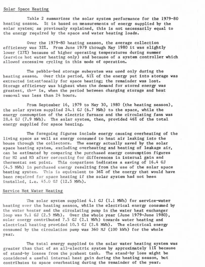
The d a i l y average power supplied by the space heating system of H3, i.e. the "net" heating power, is plotted against the d a i l y average indoor-to-outdoor temperature difference i n Figure 5a. Much of the scatter in t h e data is due to the h i g h l y variable a i r leakage component in the space heating load. The scatter a l s o r e s u l t s becamse energy
s t o r e d in the mass of the b u i l d i n g durlng periods of overheating is released at a later rime.
Y7c Lest loss factor for R3, as determined by the s l o p e of the
least-squarcs s t r a i g h t - l i n e fir t o the data, was 158 w/K.' The heat loss factor f o r HZ was 135
WIK
and the c h a r a c t e r i s t i c l i n e fs shown fn Figure 5a for comparison. The difference in t h e heat l o s s factors of the t w ohouses Fs mainly attributable to the greater a i r change rate of H 3 . The
difference in t h e i n t e r c e p t s w i t h zero heat k n p u t i n d i c a t e s a higher
internal gain in H 3 , resulting from thermal losses from the aervfce-water heating system and the pebble-bed heat storage unlt, as well as heat
i n p u t from the d a t a logging system,
The d a t a for H 3 were r e p l o t t e d in Figure 5b to illustrate the e f f e c t of s o l a r collector operation on t h e house loss characterfstic.
Data representing those days with no active solar collection w e r e
distinguished from data f o r those days w i t h more than 5 hours of solar collection. The days with solar c o l l e c t i o n show a h i g h e r heat lass
factor and s l i g h t l y higher internal gains; that is, m o r e energy w a s required and supplied to EL3 with solar collection than without
collection. This higher loss f a c t o r is consistent w i t h a higher a i r
change rate during solar callectian.
Figure 6 compares t h e heating energy s u p p l i e d in H2 and H 3 aver
t w o heating p e r i o d s : t h e f i r s t p e r i o d includes only the six c o l d e s t months of the heating season; the second i n c l u d e s the entire h e a t i n g
season, The cold period p r a v l d e s a better basis f o r comparing the heating energy r e q u i r e d by. the t w o houses since, in cold weather, the
energy s u p p l i e d is more nearly equal to that required. The gross heatfng energy supplied to H3 daring the cold period was about 14% greater than
that s u p p l i e d to H2. Much of t h i s d i f f e r e n c e w a s due to t h e higher air change rate in H3, but a part was due t o a higher indoor temperature in H3, resulting from a high thermostat set point and a limited amount: of
overheating.
The longer period allows comparison of the seasonal space
heatlng energy consmptlrpn in t h e two houses; mch of t h e eneraJ s u p p l i e d to H3 during September, October, A p r i l and May was uncontrolled, and was
Solar Space Heating
Table 2 summarizes the solar system performance for the 1979-80 heating season. It is based on measurements of energy supplied by t h e solar system; as previously explained, this i s nat necessarily equal to
t h e energy required by the s p a c e and water heating loads.
Over the 1979-80 heating season, t h e average collectton efficiency was 32%. From June 1979 through May 1980 i t w a s s l i g h t l y lower (27%) because of h5gher operating temperatures during summer
{service h o t water heating o n l y ) and because of a system controller which allowed excessive cycling in this mode of operation.
The pebble-bed s t o r a g e subsystem was used o n l y during the
h e a t i n g season. Over t h i s p e r i o d , 61% of t h e energy p u t into storage was extracted i n t : z n t t o n a l l y for space heating; the remainder w a s lost.
Storage efficfency was h i g h e s t when the demand for stored energy was greatest, th*+ is, when the period between charging storage and heat removal was less than 2 4 hours.
From September 16, 1979 to May 30, 1980 (the heating season), the s o l a r system s u p p l i e d 24.1 GJ ( 6 . 7 MWh) to the space, while t h e
energy consumption of the electric furnace and the circulating fans was
28.4 GJ ( 7 . 9 MWh)
.
The s o l a r system, then, provided 46% of the t o t a lenergy s u p p l i e d for space heating.
The foregoing figures include energy causing overheating of the l i v i n g apace as well as energy consumed to heat air leaking into the house through the c o l l e c t o r s . The energy a c t u a l l y saved by the solar space heating s y s tern, excluding overheating and h e a t i n g of Peakage air, can be estimated by comparing the purchased energy consumption figures f o r H2 and H3 a f t e r correcting for differences in internal gain and thermostat set p o i n t . T h i s comparison indicates a saving of 16.4 GJ
(4.5 MWh) in purchased e n e r g y r e s u l t f n g from the use of he solar space h e a t i n g system. F I L S is equivalent to 36% of the energy t h a t would have
been r e q u i r e d f o r space h e a t i n g if the s o l a r system had not been
i n s t a l l e d , i . e . L 5 . 0 GJ (12.5 MWh), Service Hot Water Beating
The solar system supplied 4.1 GJ (1-1 MWh) for service-water
h e a t i n g over t h e h e a t i n g season, while the e l e c t r i c a l energy consumed by t h e water h e a t e r and the c i r c u l a t i n g pump in the water heat exchanger loop was 9 - 1 GJ (2.5
MWZI).
Over the whole year (June 1979-June 19801, s o l a r energy contributed 7.5 GJ (2-1 MWh) towards water heating ande l e c t r i c a l h e a t i n g p r o v i d e d 10.3 GJ (2.8 PIWh), The electrical energy consumed by the c i r c u l a t f o n pump was 360 HJ (100 kWh) f o r t h e whole year.
The t o t a l energy s u p p l i e d to the solar water h e a t i n g system was greater t h a n t h a t of an all-electric system by approximately 11% because
of stand-by losses from the preheat rank. The stand-by loss might be c o n s i d e r e d a useful internal heat g a i n during the heating season, but contributes to space overheating during the remainder of the year.
T o t a l Solar Contribution
Of 108 GJ ( 3 0 MWh) of solar energy Incident sn the collector
array d u r i n g the 1979-80 heating seasort, 34.5 GJ (9.6 MWh) were c o l l e c t e d and 28.2 GJ (15.9 MWh) were supplied to the space and water heating
l o a d s . It is estimated that H3 would have cansmed 57.4 GJ (15.9 ~ W l z ) over t h e hearing season for space and hot water heating with no solar
system. Qn t h i s basis, the energp saved by the solar system over t h e
heating system is estimated to be 19-9 GJ (5.5 Wh). Allowfng a credit
for summertime service water preheating, t h e anrmal s a v i n g would be about 21.6 GJ (6.0 MWh) based on an estimated annual consumption of 60.5 GJ
( 1 6 . 8 MWh] w i t h no solar heating. Na credit has been a l l o w e d f o r wintertime h e a t i n g of vanrilatian air.
It must be remembered that house M3 was unoccupFed during the
study period. Occupancy would have resulted in an overall increase 5n i n t e r n a l gain and, hence, in a larger solar contrfbution to the nee heating energy k t would a l s o have meant reduced energy and d o l l a r savings.
DLS CUSSION
The solar system i n s t a l l e d in R3 sfgnlficantly reduced t h e
q u a n t i t y of heating e n e r e purchased from t h e u t i l i t y , but had several d e f i c i e n c i e s which reduced its usefulness as a h e a t i n g system. The f o l l c w i n g d i s c u s s i o n is intended to p r o v f d e some perspective on these d e f i c i e n c i e s as they might apply to similar system in t h e future.
The main concerns associated w i t h this type of solar system are: high cost, service Life a n d af r leakage problew. C o s t was and st111 remains an area o f concern. According to one manufacturer, a similar a i r s y s tern, capable of d e l f v e r i n g the same amount of energy,
i n s t a l l e d on H3 in 1981 would c o s t $11 300, or $8 000 in 1977 dollars.
Although the cost of t h e system has been reduced subs tantially since 1977, it may s t i l l remain less attractive a s an energy-savtng investment than conventionaf e n e r g conservtng o p tf ons.
Durability of solar collectors w i l l remain an area of concern. f 7 Evidence of moisture withln t h e g l a z e d colllectors would fndlcate t h a t service life and thermal performance w i l l be affected in some f ashlsn; however, some s o l a r water heating systems have remained operational for more than 25 years,8
I n solar systems similar t o that i n s t a l l e d in H3, air leakage
w i l l affect: t h e tlherml performance of the house fn several ways. It will increase the space heatlng load in winter and c o n t r i b u t e to
overheating of the indoor space during the other three seasons. S i n c e e x f i l f x a t i o a is increased, operation o f the solar system may a l s o increase i n t e r s tirial condensation w i t h i n t h e e x t e r i o r envelope of the house; t h i s , in t u r n , can s e r i o u s l y affect the d u r a b i l i t y a£ the house.. It has been argued that a solar system, installed l a a t i g h t house such as R 3 , is performing a u s e f u l fanctfon by heatfng the v e n t i l a t i o n air
Leaking in through t h e solar collector, This small b e n e f i t , hmever, would appear t o b e outweighed by the risk of damage PO the b u i l d i n g envelope,
A i r leakage I s not a concern in l i q u i d based systems and there are a number of d e s i g n approaches t h a t could greatly reduce leakage-
related problems in air-based systems. One manufacturer of an air system simflar to t h a t i n s t a l l e d i n R3 claims t h a t a collector redesign and t h e use of seamless ducting has effected a r e d u c t i o n in c o l l e c t o r array leakage from 35% to apprsxltmarely 1% of the mass f l m through the array.
COACLU S ION
As o r i g i n a l l y installed, the solar system d i d not perform to
d e s i g n expectations. Following a more careful commissionfng process, the performance approached that predicted by the manufacturer, supplying approximately 45% of t h e annual space and s e r d c e water heating energy.
This particular solar system had considerable atr leakage which reduced sys tern performance, increased the house heat f oad, overheated the indoor space and, by pressurkzfng the indoor space, increased the risk of moisture damage to the b u i l d i n g envelope,
A t an expenditure of $24 000, the system was n o t intended t o demonstrate an economical heating system. Instead, it was intended t o show t h e potential energy savings with air-type solar systems available
at the t i m e of Installation (1976-77). It a l s o served to i n d i c a t e those areas requiring further system development, such as the air leakage
problem and moisture acmrnulation w i t h i n rhe collectors.
The authors would like to thank Dr. C . Y . Shaw for t h e use of
h i s air leakage and air change data. They would a l s o lfke to acknllwltedge the assistance of M . O . P e l l e t i e r and D.L. Logan in instrumenting and monitoring t h e p r o j e c t and M. Bien, M , J , Lavoie and B. Dowden in processing the data.
REFERENCES
1. Quirouette, R.L. The Mark XI Energy Research Project
-
Design and Construction, National Research Council of Canada, D i v i s i o n of B u i l d i n g Research, Building Research Note 131, Ottawa, October 1978,2. Brown, W.C. Mark
XI
Energy Research Project-
Comparison of Standard and Upgraded Houses, National Research Council of Canada, Division of Building Research, Buildfng Research Note 160, Ottawa, June 1980- 3. Shaw, C.Y. and Tamusa, G.T. Mark XI Energy Research Project-
Air-Tightness and Air-Infiltration Measurements, Rational Research Council of Canada, Division of Building Research, B u i l d i n g Research Note 1 6 2 , O t t a w a , June 1980.
4 . Cane, R,L.D. Ffeld Performance of an Air-Source Neat Pump in the HITDAC Mark XI Research Energy P r o j e c t , National Research CouncFl of Canada, Divlslon of B u i l d i n g Researzh, B u i l d i n g Research Note 174, Ottawa, May 1981.
5 . Beach, R,K. Relative Tightness of New Housing in the Ottawa Area, National Research Council o f Canada, Division of Building Research,
Building Research Note 149, Ottawa, June 1979.
6 , Skoda, L.P. and Masters, L.W. Solar Energy Systems
-
Survey d fMaterials Performance, F i n a l Report, Energy Research and Development Administration, NBSIR 77-1314, Washington, October 1977.
7. Lorriman, D. Art Assessment of Problems Experienced with Operating Solar Systems tn Canada and t h e Northern United S t a t e s , National Research Council of Canada, Solar Energy Project, Solar Technical Series No. 1, Ottawa, December 1978.
8. Robertson, W.A., GeorgTa Genealogy, Solar Age, Vol. 5, No. 3,
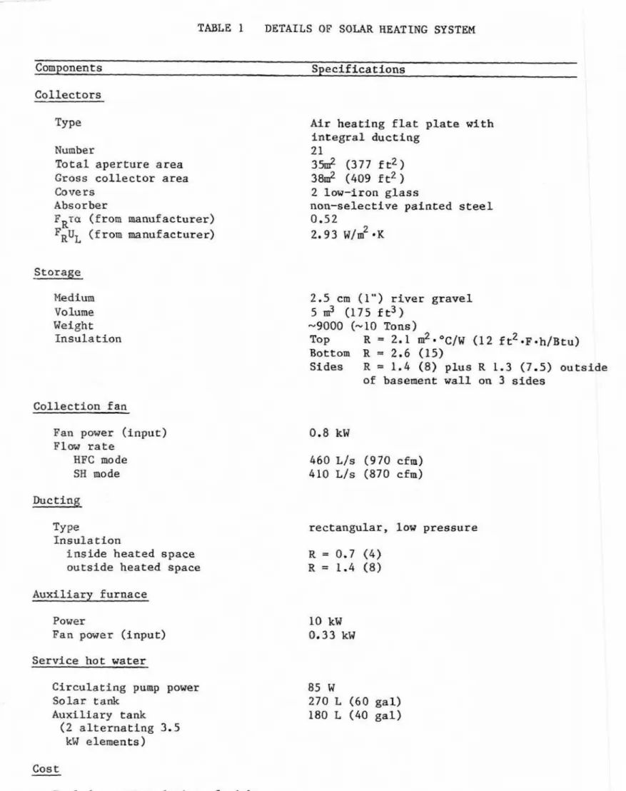
TABLE I DETAILS OF SOLAR HEATING SYSTEM
Components Specificattons
Collectors
Number
T o t a l aperture area Gross collector area Covers Absorber FGQ (from manufacturer) FR% (from manufacturer) Medium Volume Weight Insula tfan Collection f a n
Fan power (input) Flaw r a t e HPC made SH mode Type I n s u l a t i o n i n s i d e heated space outside h e a t e d apace Auxiliarv furnace Power
Fan power (input) Service h a t water
Circulating pump power S o l a r t a&
Auxiliary tank
( 2 alternating 3.5
kW elements )
Cost
Includes system design, freight,
import duty and ins t a l l a t i o n
Air heating flat plate with integral d u c t i n g 21 3 5 d (377 f t 2 ) 38m2 (409 f t 2 ) 2 law-iron glass nun-selective p a i n t e d s t e e l 0 -52 2.93
WE^'
mK 2.5 em ( 1 " ) river gravel 5 - 2 (175 f t 3 ) -9000 (-10 Tons) T o p R = 2 . 1 d ~ 0 ~ / ~ ( 1 2 f t Z - ~ ~ h / ~ t u ) B o t t o m R 2.6 (15) S i d e s R = 1.4 (83 p l u s R 1 - 3 (7.5) outside of basement wall on 3 s i d e srectangular, low pressure
85 W
270 L ( 6 0 g a l )
MARK XI HOUSE
2 EARTH BERM 2.5 rn HIGH
F I G U R E 1
TEMPERATURE MIXING VALVE HOT WATER &I
I
I fA
OUTSOLAR AUXl LI ARY
H.W. l r H.W. TANK
d
TANK-
MAINS SUPPLY WATER IN +1
PUMP MOTORIZED ELECTRIC
.
COLLECT1 ON DAMPER FURNACEHEATED SPACE PEBB LE'BE P STORAGE II . O h . . , , L , . * + RETURN #
1
BACK DRAFTI
F I G U R E
2
S O L A R
S Y S T E M S C H E M A T I C
DAM PE RS IT H E A R R O W S I N D I C A T E P R E S S U R E D I F F E R E N C E S THAT WERE M E A S U R E D W I T H THE S Y S T E M O P E R A T I N G IN THE H E A T I N G - F R O M - C O L L E C T O R ( H F C ) A N D STORING-HEAT ( S H ) MODES C O L L E C T O R
,
SUPPLY DUCT / / 0 C O L L E C T O R C O L L E C T O R / P R E S S U R E DIFFERENCE,Pa
F I G U R E3
A I R L E A K A G E C H A R A C T E R I S T I C S OF THE C O L L E C T O R A R R A Y AND THE S U P P L Y A N D R E T U R N D U C T S...
"111 a*...---
HOUSE 2 INDOOR TEMPERATURE...-...,...-.
-
HOUSE 3 INDOOR TEMPERATURE.----
OUTDOOR A M B I E N T TEMPERATURE (0) SEPTEMBER 27, 1979 STORING HEAT30
20
10
0
-10
0-20
0-
W E 3 C<
30
W [L 5220
+
---
H W S E 2 INDOOR TEMPERATURE-
HOUSE 3 INDOOR TEMPERATURE10
----..
OUTDOOR AMBIENT TEMPERATURE SH STORING HEATHFC HEATING FROM COLLECTOR
0
HFS HEATING FROM STORAGE(b) MARCH 12, 1980
-10
... ...
0
2
4
6
8
10
1 2
1 4
16
1 8
211
22
24
TIME,
h
H O U S E T E M P E R A T U R E S A N D
S O L A R
S Y S T E M
O P E R A T I N G
M O D E S
(0) HEAT LOSS CHARACTERlSTlCS OF HZ (ELECTRICALLY
HEATED) A N D H3 (SOLAR HEATED)
8
HOUSE 3 DATA
PH3 = 0.158
A
T-
0.844*
soMR
COLLECTOR OPERATION>
5.0 h/hYP = 0.158
AT
-
0.598, SOLARo NO SOLAR COLLECTOR OPERATION
P = 0.138 A T
-
0.461,10
8
A V E R A G E
D A
l L Y T E M P E R A T U R E
D I F F E R E N C E ,
K
F I G U R E 5
I I I 1 I I 1 1I
-
(b) EFFECT OF SOLAR COLLECTOR OPERATION 3 ON HEATING POWER-
HOUSE 3A V E R A G E D A I L Y H E A T I N G P O W E R V E R S U S
A V E R A G E D A
l L Y T E M P E R A T U R E D I F F E R E N C E
C O L D
P E R I O D ,
S E P T 1 6 - M A Y 3 1 4 4 6 B ° C - D A Y S GROSS 55.0 GJ GROSS 48-3 GJ NET 44.3 G J GROSS 65.8 GJ NET 52.7 GJ GROSS 52.6 GJ NET 47.3 G3AVERAGE lNDOOR-0UTDQOR TEMPERATURE DIFFERENCE