Splitless Injection on Capillary Columns, Part 1.
The Basic Technique
;Steroid Analysis as an Example
by K. Grob and G. Grob, Department of Organic Chemistry, University of Zurich, Switzerland.
Abstract
A very simple procedure for splitless injection on cap-illary columns is discussed. In contrast to more sophisti-cated devices recently developed for the same purpose, the method described requires no additional equipment. The ad-vantages of the method which broadens the use of capillary columns are discussed. Steroid analysis serves as an exam-ple of the applications.
Introduction
Injection on capillary columns without splitting has long been desired by practical chromatographers. Among the various reasons for this are the following:
Splitting may easily cause quantitative errors. The refined equipment needed for proper splitting has large adsorptive surfaces and is difficult to keep clean.
Sample losses due to splitting are troublesome in the case of expensive or toxic samples.
Large volumes of dilute samples cannot be injected with splitting.
These and other reasons have led to considerable effort in developing injection techniques which would avoid splitting without affecting separation efficiency. Excellent results have been accomplished by workers at the Technical University of Eindhoven (1-3). The apparatus and methods described by these authors rep-resent a further development of injection devices re-ported earlier ( 4,5). The latter consist in a trapping loop, i.e. a small capillary length, which is cooled dur-ing injection and, after introduction of the total sam-ple, is quickly heated to start separation. While such devices work well, e.g., with dilute gaseous samples, difficulties are encountered with diluted solutions. Large amounts of solvent tend to plug the capillary when they are condensed in the chilled part.
We wish to demonstrate a much simpler method of splitless injection which provides maximum efficiency without additional equipment. We have found that a relatively moderately cooled column is itself a very efficient trapping system. If during injection the col-umn temperature is held to at least 100° C below the bolling point of the most volatile sample component, and if after injection the column is slowly or rapidly heated to the normai analysis temperature, then full separation efficiency is observed even when the
injec-tion
has been carried out very slowly or with
inter-ruption. This
means that a substance boiling at
120° C may be ideally resolvedafter injection on a column at
room
temperature withsubsequent heating
to an analy-sistemperature of
e.g., 80° Ceven when the well-known
precautions of sample introduction on capillary
col-umnshave been neglected entirely.
The
minimum differentebetween
column tempera-ture and boiling point of sample is strongly dependent upon the functionality of the sample as well as on the liquid phase.The basic principle of this simple injection method was discussed by Rushneck
(6)
in 1965. Apparently, however, the author did not further study the broad applicability of the idea. A special application of the same principle was described by Lewins and Ikeda ( 7 ). Merrit, Walsh and coworkers (8), (with references to earlier work) gathered wide experience with injec-tion on cold columns. Again, their purpose was not splitless injection but rather analysis of wide boiling mixtures.In this paper we wish to present steroid analysis as an example for splitless injection on glass capillary columns. In a second part we shall discuss the detailed conditions and limits as well as more specialized appli-cations of our injection method.
Experimental
We used a 20 m long and 0.26 mm diameter glass capillary pretreated for nonpolar coatings as described earlier
(9).
The liquid phase was silicone oilOV 101
with a film thickness of approximately .07 p,. Helium
was the carrier gas flowing with an average velocity of
I. Cramers, C. A., and Van Kessel, M. M., J. Gas Chro-matog. 6. 577 (1968).
2. Groenendijk, H., and Van Kemenade, A. W. C., Chro-matographia, 2, 107 (1969).
3. Kuppens, P. S. H., Informal Symposium, GC-Discus sion Group, London, March 1969.
4. Bartel, E. E., and Van der Walt, S. J., J. Gas Chro-matog. 6. 396 (1968).
5. Willis, D. E., Anal. Chem. 40, 1597 (1968).
6. Rushneck, D. R., J. Gas Chromatog. 3, 318 (1965). 7. Lewins. R. J., and Ikeda, R. M., J. Gas Chromatog.
6,331 (1968).
8. Merrit, C. Jr., Walsh, J. T., Forss, D. A., Angelini, P., and Swift, S. M., Anal. Chem. 36, 1502 (1964).
9. Groh, K., Helvetica Chimica Acta 51, 718 (1968).
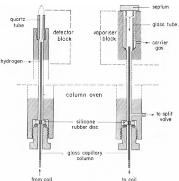
quartz - -tube detector block I vap oriser block glass tube -- corner gas hydrogen column oven silicone rubber disc glass capillary column , to split valve
from coil to. coil
7 9 A Synthetic Sample B iz Mixture Natural Synthetic 67 0 Naturel Sample 230• 20° 170° 3° /min 5 15 15 20 25 20 55 min
60 cm per second, which corresponds to 1.6 ml per
minute. The column was mounted in a Carlo Erba,
(Milano) Model GI gas chromatograph with an
all-glass system (Figure 11
.The capillary starts inside
a glass tube in which sample evaporation and splitting
takes place. The tube is easily removed for inspection
and cleaning. The outlet ends 1 mm below the 8 mm
long quartz jet of the FID, which allows hydrogen to
enter from the side, mix with the column stream, and
flow to the flame. Thus the sample never contacts
metal. Dead volume from column inlet to detector is
practically zero. Vaporizer and detector can be heated
above the temperature limit of the silicone rubber
fittings since the Jatter are sufficiently distant from
the heated parts as to be exposed to column
tempera-ture only.
septum
Figure 1. Diagram of column inlet and outlet system (not on scale).
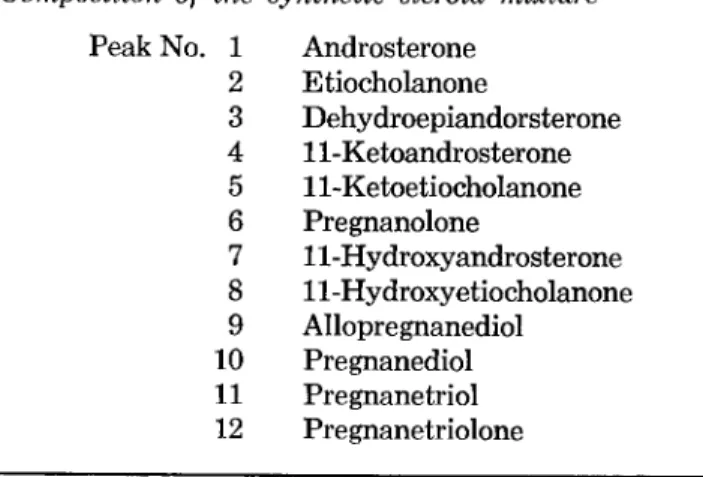
The synthetic sample of 12 steroids-TMS was
iden-tical to that used in the work by Curtius and Midler
(10). This sample as well as that extracted from urine
was kindly supplied by the laboratory of Dr. Curtius.
The individual steroids were present in a concentration
of approximately .01%, the solvent being the silylating
agent bis (trimethylsilyl) acetamide. For reproducible
injection of small amounts of solution, we filled the
syringe needle (Hamilton 701-N1 with hexane, then
introduced 0.3 (cl of sample followed hy 0.2
til of air.
During injection approximately 0.7
ittl of liquid was
evaporated whereby the known amount of sample was
completely flushed out of the needle by the
evapo-rated hexane. A similar injection procedure bas
re-cently been described by Kruppa 11
The exact procedure leading to the chromatograms
in Figure 2 was as follows:
Figure 2. Analysis of steroid mixtures injected without split-ting. Column: 20 m1.26 mm glass coated with OV 101. He flow 1.6 ml 'min. FID. Samples and procedure see text.
1. Adjust base line at oven temperature 230° C,
col-umn flow 1.6 ml/min, split flow 20 ml/min.
2. Stop heating and open column oven to ambient air.
3. Close split valve.
4. When column has reached room temperature
intro-duce sample as described in the foregoing
para-graph.
5. 30 sec after injection open split valve to yield a
side stream of 20 ml/min to clean up the injection
port from back-diffused sample traces.
6. 60 sec after injection close column oven and heat
rapidly to 170°C.
7. 7 min after injection start temperature program
3°/min from 170 - 230°C. (Isothermal period at
170°C depending on the need of separating solvent
and its byproducts from sample peaks).
10. Curtius, H.-CH., and Midler, M., J. Chromatog, 32, 222 (1968).
11. Kruppa, R. F., GC-Newsletters, Applied Science, Jan. 1969.
To obtain some tentative identif kation for the urine steroids we mixed the natura! sample with the synthetic one (run B, Figure 2 i Most of the urine peaks showed exact coincidentie with peaks of the synthetic mixture n Synthetic Sample 170• 5 15 15 35 35 min
Figure 3. Sample and column as used for figure 2A. Ordinary injection with splitting at 170'.
The chromatogram shown in Figure 3 was obtained from the synthetic steroid mixture after ordinary in-jection with splitting at 170°C. Whereas for splitless injection the vaporizer temperature was 210°C, it was raised to 270°C for splitting to provide rapid evapora-tion. The somewhat poorer separation and the in-creased tailing (as compared with run A, Figure 2), is caused by minute impurities in the vaporizer tube. Traces of nonvolatile sample material or, more aften, small particles of septum rubber strongly adsorb sub-stances with low vapor pressure, such as steroids, and release them over a period sufficiently long to cause tailing. Cleaning the tube after every run reduces but normally does not eliminate the trouble. This is never observed after splitless injection since the sample is completely evaporated, even out of a dirty vaporizer tube, before separation starts. The poor baseline in Figure 3 is caused by septum bleed. It could not be overcome at our high sensitivity and high vaporizer temperature even after long continuous use. It can of course be made invisible by strictly using isothermal conditions.
Conclusions
The essential detail of our injection procedure is the temperature differente between the column and the boiling point of the most volatile sample compo-nent. During injection, the column temperature must
Composition of the synthetic steroid mixture
Peak No. 1 Androsterone
2 E tiocholanone 3 Dehydroepiandorsterone 4 11-Ketoandrosterone 5 11-Ketoetiocholanone 6 Pregnanolone 7 11-Hydroxyandrosterone 8 11-Hydroxyetiocholanone 9 Allopregnanediol 10 Pregnanediol 11 Pregnanetriol 12 Pregnanetriolone
be high enough to allow elution of the solvent and by-products or at least to prevent condensation. On the other hand, the temperature must be low enough to provide trapping of the most volatile sample compo-nent. Under wel!-adjusted conditions the procedure offers the following advantages:
Elimination of quantitative errors possible caused by splitting.
Complete elimination of sample losses.
No need for rapid evaporation. Thus, the va-porizer temperature is lower which leads to less sample breakdown and less septum bleed. Analysis of very dilute samples without previ-ous concentration.
Large amounts of air, e.g. head space samples, can be injected without harm to the column since oxygen is eluted from the cold column. No loss of resolution due to adsorption-desorp-tion effects in the vaporizer.
Very simple equipment with minimum adsorp-tive surface and easy cleaning instead of sophis-ticated devices, e.g. mixing chambers and linear splitters.
Whereas most of these advantages represent rela-tive improvements of varying importante, the potential for analysis of very dilute gases or solutions opens a new use for capillary columns.
A drawback of our simple procedure resides in the impossibility of working isothermally The effect is re-duced by Groendijk's and Van Kemenade's (2) cold spot and heat sink, which does allow constant column temperature. According to our experience the cor-responding injection device should, however, be much simplified since there is no need for a special design to include very high evaporation temperatures.
Manuscript received May 13, 1969