HAL Id: hal-01359250
https://hal.inria.fr/hal-01359250
Submitted on 5 Sep 2016
HAL is a multi-disciplinary open access
archive for the deposit and dissemination of
sci-entific research documents, whether they are
pub-lished or not. The documents may come from
teaching and research institutions in France or
abroad, or from public or private research centers.
L’archive ouverte pluridisciplinaire HAL, est
destinée au dépôt et à la diffusion de documents
scientifiques de niveau recherche, publiés ou non,
émanant des établissements d’enseignement et de
recherche français ou étrangers, des laboratoires
publics ou privés.
EgoSAR: Towards a personalized spatial augmented
reality experience in multi-user environments
Brett Ridel, Lois Mignard-Debise, Xavier Granier, Patrick Reuter
To cite this version:
Brett Ridel, Lois Mignard-Debise, Xavier Granier, Patrick Reuter. EgoSAR: Towards a
personal-ized spatial augmented reality experience in multi-user environments. IEEE International
Sympo-sium on Mixed and Augmented Reality (ISMAR-Adjunct), Sep 2016, Merida, Mexico. pp.64-69,
�10.1109/ISMAR-Adjunct.2016.0041�. �hal-01359250�
EgoSAR: Towards a personalized spatial augmented reality experience in
multi-user environments
Brett Ridel∗ Inria, LaBRI Lo¨ıs Mignard-Debise† Inria, LP2N Xavier Granier‡ Inria, LaBRI, LP2N Patrick Reuter§ Inria, LaBRI, Universit ´e deBordeaux
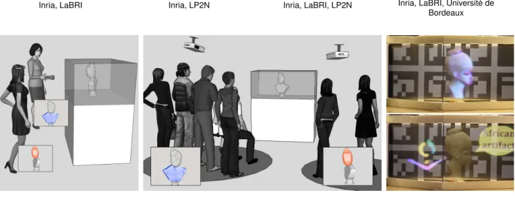
(a) active scenario (b) passive scenario (c) augmentations
Figure 1: Our vision of EgoSAR. (a) In an active scenario, the users are wearing or holding a projector that augments a real artifact in a personalized way: the respective augmentation can only be seen by themselves. (b) In a passive scenario, the users look at a real object from predefined viewpoints. Each viewpoint offers a different augmentation and is thus personalized. (c) In both scenarios, the real-world object and the personalized virtual information are visible. The view-dependent personalized information such as curvatures can be superimposed on the object (c-top) or shown aside, for example for annotations (c-bottom).
ABSTRACT
Common spatial augmented reality techniques use video projection to superimpose virtual information over a physical scene. As the augmentation happens directly in the real world, multiple users can see the augmented scene, however, the augmentation is the same for all users. We introduce EgoSAR, a new approach that makes it possible to have a personalized, view-dependent augmentation, in multi-user environments. Our key idea is to use retroreflective ma-terial for the personalized experience, in conjunction with spatial augmented reality, by combining two different light paths. We im-plemented our approach in two prototypes combining transparency and either direct or indirect retroreflection. We present two differ-ent usage scenarios, show results, and experimdiffer-ent applications that such an approach may provide.
Keywords: Spatial Augmented Reality, Retroreflective & Semi-Transparent Display
Index Terms: H.5.1 [Artificial, augmented, and virtual realities]: —
1 INTRODUCTION
Today, augmented reality applications are a popular way to display virtual information in real worlds, and they are becoming available to the masses. There are two main categories that are conceptually different: on the one hand, see-through augmented reality augments
∗e-mail: [email protected] †e-mail:[email protected] ‡e-mail:[email protected] §e-mail:[email protected] retroreflective reflective diffuse
Figure 2: Three main surface properties: for the diffuse case, the light is uniformly reflected in all directions. For the perfectly reflec-tive case, the light is reflected only in the mirror direction. For the retroreflective case, the light is reflected in the emitted direction. the real world that is sensed by, in most cases, a camera, and the augmentation is displayed on individual consumer screens such as tablets, smartphones, or glasses. On the other hand, spatial aug-mented reality(SAR) augments the real world by superimposing information by video projection, and hence the consumer looks at the real augmented world directly, and not on a screen. The ap-plication contexts of both categories are also quite different. In see-through augmented reality applications, nowadays the user is autonomous: he or she can choose among the wide variety of ap-plications that have become available out of the box on the popular application stores for different domains, such as transport, tourism, education, archeology, games, just to name a few, and individually interact with the augmented world [21].
In contrast, in SAR, most of the time the user takes part in a public event or a public exhibition. Since the initial and formerly ”futuristic” idea of Henry Fuchs to create an office of the future with shared telepresence created by a sea of cameras and video-projectors [25], SAR has become mature and is a widely appreci-ated way for enriching real worlds with virtual information. Appli-cations range from entertainment [31], medicine [18], archeology [27], and many more.
One of the major advantages of SAR is that several users can participate in the same experience. Unfortunately, depending on the application, this fact can also be a downside: it often translates to passive users, or one interacting lead user, since the result of
in-teraction is visible to the entire audience. This is especially true when the video projector is at a fixed location, and when it projects to a diffuse surface (Figure 2 left ). On the other hand, person-alized video projectors, such as head-mounted projective displays (HMPDs [10]), are often used together with a retroreflective mate-rial that is put in the environment. Retroreflective matemate-rials redi-rect the projection back to the incoming diredi-rection (Figure 2 right), and hence towards the user who is wearing a HMPD, thus creating a personalized visualization. However, the retroreflective material that is used is opaque, and consequently the scene behind it is in-visible, resulting in a limited SAR experience.
In this paper, we propose to overcome this limitation and present a new approach for a personalized SAR experience in multi-user environments where the real objects to augment are not occluded. We also use retroreflection to personalize the experience for the users being in the direction of the light emitted by video projectors. In addition, our key idea is to use the retroreflective material in a way that the users, together with other observers, can also see the real object that is augmented. We call our approach EgoSAR to emphasize the personalized spatial augmented reality experience, and we propose two different implementations of our idea. In the first one, we use directly a semi-transparent retroreflective film that is placed in front of the object, and that we specifically designed for our purpose. In the second implementation, we indirectly use an opaque retroreflective film that is put sideways between the user and the object to augment, in conjunction with a beam splitter that is placed in front of the object at an angle of 45 degrees. With both implementations, we tend to obtain the best of both worlds: it is still possible to see the real object, and the retroreflection of the emitting light enables view-dependent and thus user-specific augmentations. Despite the early prototyping stage, we already see that our new method reflects a high potential for a number of applications. We designed two proof-of-concept applications that are both targeted to museum exhibitions. We deliberately use this application con-text because museums have several visitors at a time, and it is cru-cial to maintain a view of the real artifact to augment. Moreover, precious artifacts are often protected by a glass pane that we can naturally use for our augmentation purpose. In the first application, the visitors that want to have a personalized experience carry their own projection system (Figure 1(a)). In the second application, the users do not even need to carry or wear a specialized equipment: we use multiple video projectors at fixed locations and constrain the viewpoints of the users by the physical design of the exhibition space (Figure 1(b)).
The remainder of this paper is organized as follows. In Section 2, we present related work. In Section 3, we present the general idea of our approach and two application scenarios. In Section 4, we explain details of the setup and of our implementation. Finally, in Section 5, we present and discuss our first results, before we conclude in Section 6 and present directions for future work.
2 RELATED WORK
The first use of the term SAR dates back to 1998 [26]. Ideally, a diffuse object with smooth geometry is augmented with virtual information in the user’s physical space by means of a video pro-jector, observable by multiple users. Since then, various variants have been developed that can also be attributed to the family of spa-tial augmented reality applications. In the following, we provide an overview of existing approaches where some of their characteristics can be considered close to our objective: creating a personalized SAR experience in multi-user environments.
Retroreflective displays: Retroreflective material is often used together with mobile projection systems, such as, for example, head mounted projective displays (HMPDs). Either by wearing
glasses [10, 8, 9, 7], or without glasses [16, 1], this results in a personalized experience. A similar system is currently commer-cialized [3]. However, besides [16] who raise the possibility of us-ing perforated retroreflective material, to the best of our knowledge, previous approaches only make the augmentation on an opaque sur-face without taking into account the scene behind it [11, 16, 1]. Semi-transparent displays: Semi-transparent displays have been around for some time now, and there is still active research on this topic. Some semi-transparent displays can be designed as touch-screens [32] or midair gestures [24], by using reflection [23, 17], in order to show information about invisible or hidden objects [4]. Recently, Plasencia et al. [17] proposed a semi-transparent screen based on optical combiners. A scene behind a glass pane is aug-mented, while preserving the visualization of the real scene in front of the glass pane. All these approaches have in common that the ex-perience can be shared between multiple users, however, with only one single augmentation at a time, no personalized experience is possible.
Floating images: Aerial Imaging by RetroReflection (AIRR) is a system that gives the illusion of a floating image, based on a beam splitter, a retroreflective surface, and a flat screen [33, 28], which can be associated to a projector array [34]. However, these ap-proaches are designed to create a floating image, and have not been used to augment real-world objects’ surfaces.
On the other hand, the Active-shuttered Real Image Autostere-oscopy (ARIA) creates a floating image by using a system with a screen, a shutter, and a fresnel lens [22, 29]. This floating image can be located around a real-world object. However, in this system, the surface of the real-world object itself cannot be augmented, and the floating image cannot be located in front of it.
Autostereoscopic/3D displays: Butler et al. [2] proposed a system where multiple users can see a floating image. Their system is com-posed of a projector, a high speed spinning diffuser, and a parabolic mirror. Yoshida et al. [34] proposed a different system for a single user, based on a beam splitter, a projector array, and retroreflective material. Note that both approaches involve complex systems, and the area of visibility is rather small.
Other approaches for multi-user glasses-free autostereoscopic dis-plays have been explored, either with a 1D array [14] or a 2D array of projectors [12, 13] combined with diffuser screens. All these approaches require a quite involved infrastructure (computers, pro-jectors), and also space. Moreover, only a virtual image can be generated, and the real object cannot be seen through the system. The system of Karnik et al. [15], based on a random hole see-through display, makes it possible to see personalized virtual im-ages behind real objects. However, even with their strategy for the management of conflicts, the higher the number of users, the worse the quality of the images. Moreover, the surface of an object that is placed inside the system cannot be augmented.
Many other solutions [6] have been explored recently to extend the resolution in space and direction to reach a full 3D display - the ulti-mate solution for a multi-user approach. However, to the best of our knowledge, no solutions have been proposed where transparency would make it possible to maintain a view of the real scene.
3 OURAPPROACH ANDAPPLICATIONSCENARIOS
A general assumption in SAR is that the support of the projection, as for example the object to augment, is diffuse. The diffuse ma-terial bounces the projection in any direction, and so all observers can see the same augmentation without wearing any equipment.
Our objective is to obtain a personalized augmentation, using a retroreflective material. As a result, the augmentation is only visible for the users where the viewing direction is aligned with the projec-tion direcprojec-tion. A straightforward soluprojec-tion would be to ”paint” the
objects to be augmented with retroreflective material. However, be-sides the fact that this is not always possible for existing objects (think of cultural heritage artifacts for example), the surface of the object itself would be occluded by the material. Our principal idea is to maintain a view of the real-world objects, and we propose to mix the retroreflective light path with the light path that is coming from the real-world objects.
Before getting into details on how to implement our idea (see Section 4), we present two scenarios where such an approach is ideally suited:
Active Scenario: As shown in Figure 1(a), multiple users in front of a showcase may wear or carry individual projection devices, and the real-object behind the glass pane is augmented in the respec-tive emitting direction. The individual projection device may be a HMPD, or any other lightweight projector. Inspired by [30], we believe that using a small hand-carried projector similar to a flash-light may leverage the feeling of being ”equipped”. Moreover, a hand-carried projector can also be used as an interaction device. Recall that by using retroreflective surfaces, the projection system and the eyes must be theoretically perfectly aligned. However, we experienced that the retroreflective behavior of our prototype im-plementations makes it possible to see the virtual information even if the viewpoint and the projector are only quasi-aligned (see Sec-tion 5 for details). Note also that mobile projecSec-tion systems have significantly improved recently. In particular, laser pico projec-tors are well adapted for the mobile setting since they are small, lightweight, and always in focus. Their rather low brightness is partly compensated by the fact that the retroreflective material save almost all the light energy.
Passive scenario: As said above, the retroreflective behavior of our prototype implementations makes it possible to see the virtual in-formation even if the viewpoint and the projector are not perfectly aligned. This makes it possible to design a passive application sce-nario, as illustrated in Figure 1(b), where multiple projectors are fixed at different locations. Depending on the position of the user, different augmentations are shown. For example, different stories about a same object can be told to the users while they are moving from one position to another. All the positions where an augmenta-tion is visible from may be indicated by the design of the exhibiaugmenta-tion space. In our example, we propose to paint circles on the floor.
4 IMPLEMENTATION
In order to implement our approach there are several material and design choices to make. In this section, we first discuss our choice of the retroreflective material. Then, we show a direct and indirect way to combine two light paths for mixing retroreflection and trans-parency (what we call semi-transparent retro in this paper). Finally, we show how to calibrate our implementations.
4.1 Retroreflective material
At first, we need to determine which material is best suited for retroreflecting the light. We tested glass beads and micro prisms, and our tests confirm previous experiences [11] that micro prisms are better suited for our targeted applications: the retroreflection happens also around a small angle around the ideal path, contrary to an energy peak with glass beads. This makes is possible that the viewing direction does not have to be perfectly aligned with the projection direction (see Section 5 for details). Consequently, we decided to use a micro prismatic retroreflective film manufactured by 3M (ref. 6260) [19].
4.2 Combining the two light paths
In order to combine the retroreflective behavior of the micro prisms and the light path that is coming back from the real-world object re-sulting in semi-transparency and retroreflection, we have designed two prototypes for personalized multi-user SAR applications.
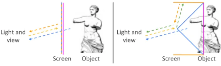
Object Screen Light and
view Light and view
Object Screen
(a) Direct retroreflection (b) Indirect retroreflection
Figure 3: Illustration of the direct and indirect retroreflection im-plementations. In both cases, when the user is quasi-aligned with the projector, he or she is able to see the real object through the screen, together with the augmentation. For the direct retrore-flection, the blue/orange line is the semi-transparent retroreflective glass (a). For the indirect retroreflection, the blue line is the beam-splitter (b), and the orange line is the retroreflective material (b). The yellow dotted arrows represents a light ray emitted by the pro-jector (a, b). The orange dotted arrows correspond to a retrore-flected ray (a, b). The blue dotted arrows indicate the transmission that enables to see the object by transparency (a, b). The green dot-ted ray is the reflection of another ray by the beam splitter (b). The pink line represents the imaged position of the augmentation.
(a) Direct retroreflection prototype (b) Indirect retroreflection prototype
Figure 4: Overview of the two prototype implementations. The red line encircles the real object. In the first prototype, the perforated semi-transparent retroreflective film (in green) is put on a trans-parent glass pane (in purple). In the second one, two retroreflective materials (in orange) are placed at 45◦to the beam splitter (in blue).
Direct retroreflection
The idea of our first prototype is quite straightforward: we created a semi-transparent retroreflective material to be put on a glass pane situated in front of an object to augment (Figures 3(a) and 4(a)). The retroreflective part makes the augmentation visible to the user. The semi-transparent part allows the light to travel from the scene behind the glass pane towards the users.
As far as we know, there is no off-the-shelf solution for a semi-transparent retroreflective glass pane. Therefore, we have proto-typed it by perforating the retroreflective film (cf. Figure 6-(right)), and we have fixed it to a glass pane. We perforated the retro-reflective film with a femtosecond laser (Yuzu model by Amplitude Syst`emes). We envision also to make the perforation with an other process, such as hole punching. Obviously, the ratio between trans-parency and retroreflectivity is directly linked to the density of the holes and their size. The larger the holes or the higher their density, the more the material is transparent and less retroreflective. Note that in order to maintain the retroreflective behavior of the mi-cro prisms, we have to keep them intact. Therefore, we propose that the step between the holes has to be at least twice the length of the base line. In the current version, the base line of the micro prisms has a length of 220µm and a height of 180µm, and we use a hexagonal mesh of holes, each one with a diameter of 1mm and with a step of 1.75mm (see Figure 6).
Pros: Since the projection support is a glass pane, the system can be installed as a classical showcase, for example in a museum. More-over, because of the retroreflective material’s properties, the glass pane can be curved or even freeform, allowing different installa-tions (for example, an object can be augmented from all sides).
Cons: Depending on the distance from the glass pane and the ob-ject to augment, the virtual obob-ject is not imaged at the same depth as the real one, therefore, the user may have to choose to focus on the real information or on the virtual augmentation.
Indirect retroreflection
Our second implementation is composed of a retroreflective film and a beam splitter (Figures 3(b) and 4(b)). The retroreflective film and the beam splitter are placed at 45◦from each other. When a ray
hits the beam splitter, it is separated into two different rays, the first one passing through the beam splitter, while the second one is re-flected at 90◦. However, contrary to [34, 33, 28], we align the light
source and the viewpoint. Since the retroreflective film is placed at 45◦from the beam splitter, the reflected ray will be sent back to the
beam splitter, and be separated again into two different rays. One of it will come back to the light emitter. Since the projector and the user are quasi-aligned, the user will receive the light emitted from the projector. Moreover, because of the configuration of the retrore-flective beam splitter, if the base of the beam splitter is at the same depth as the real object, the user will see the virtual information as a floating image, located at the same place as the real object.
We use a commercial one-way mirror film as a beam splitter that we glued to a sheet of Polyglass (2mm thickness). We advise to glue the retroreflective film in the interior part of the 45◦setup in
order to avoid refractive effects that could blur the virtual image. Pros: We are able to control the location of the floating image by adjusting the distances from the base of the beam splitter to the object, and so the virtual information is superimposed on the real object in the desired plane.
Cons: The system requires more space in front of the object. To reduce the required space, an alternative version could be a double beam splitter at 90◦from each other.
4.3 Calibration
There are several calibrations that are necessary for our implemen-tations. First, we need to do a geometrical calibration and tracking so that the virtual information is correctly superimposed over the real-world scene. Second, we have to adjust the relative intensities of the two different light paths that are combined.
Geometrical calibration
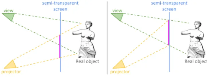
For the geometrical calibration, we need to realize the stan-dard steps of SAR applications, together with an additional post-treatment. More precisely, we need to calibrate the projector (or camera/projector, depending on the tracking solution). Then, by us-ing the intrinsic parameters (i.e. focal distances and optical centers), we instantiate a projection matrix. We compute the intrinsic and ex-trinsic parameters of our projector/camera setup with [20]. For the tracking part, we use ArUco [5] in order to locate the physical ob-ject, the projectors, and the viewpoints in the real space. Finally, we send the generated image to the projector. At this step, the projected image should superimpose the real object. However, since a semi-transparent screen is placed between the user and the real scene, if the user’s viewpoint is not perfectly aligned with the projector, and if the image plane is not at the same depth as the real object, the perceived augmentation will not be aligned with the real object. It is therefore crucial to take this shift into account (Figure 5).
Relative light intensities
Note that for both approaches, since the energy conservation with the micro prismatic retroreflective film is high, the brightness of the projector does not have to be as high as when projecting on diffuse surfaces. Nevertheless, since for the semi-transparency, we have to adjust the ratio between the two light paths real/virtual. In our direct retroreflection implementation, we can control it by modify-ing the density of the holes. In the indirect implementation, we can
Real object semi-transparent screen view projector Real object semi-transparent screen view projector
(a) Without perspective correction (b) With perspective correction Figure 5: With rendering in standard SAR applications, the user sees the augmentation (pink line) shifted with respect to the real ob-ject (left). A perspective compensation corrects the problem (right).
Figure 6: Direct retroreflection: In the left and middle images, we combine the retroreflected augmentation and the view of the object to illustrate our concept of semi-transparent retroreflection. The top right image shows our perforated retroreflective film. The bottom right image shows a close-up where each micro prism is noticeable.
Figure 7: Direct retroreflection: demonstration and residual images with one projector. In each image, the statue is augmented. Note the difference of light intensity when the viewpoint is (left) or isn’t (middle) aligned with the projector. A residual image is perceptible on the screen, because of the unwanted diffuse/glossy part. The residual image on the object is almost invisible (right).
control it by choosing a beam splitter with the appropriate reflectiv-ity/transparency ratio.
5 RESULTS ANDDISCUSSION
All our results have been generated with a Vivitek Qumi Q5 pro-jector, and the statue used in the examples has a height of approxi-mately 20cm.
Prototype with direct retroreflection: In Figure 6 (left-middle), we demonstrate what we can obtain with our direct retroreflection implementation. We clearly see both the object by transparency through the holes and the augmentation on the retroreflective film. One goal of EgoSAR is to be suited for a multi-user environment. Since the first prototype is only composed of retroreflective mate-rial, it ensures that the augmentation is projected back to each user that carries or wears a projector in the active scenario, or to the user that is aligned with a fixed projector’s viewing direction in the passive scenario. This can be seen in Figure 7, where the augmen-tation is clearly visible when the user and the projector are aligned (Figure 7-(left)). The augmentation almost disappeared for another view direction (Figure 7-(middle)).
However, our prototype also suffers from some limitations. First, the retroreflective film has some glossy/diffuse parts. This results in
(a) object (b) augmentation (c) annotation
Figure 8: Indirect retroreflection. (a) The object can be seen due to the transparency. (b) We can superimpose the augmentation. (c) We can also add floating augmentation, for example for annotations. a residual image that can corrupt the multi-user experience since it can be seen at a large set of viewpoints (Figure 7). Since this limita-tion is directly due to the retroreflective film, we will discuss poten-tial solutions and improvements in a dedicated paragraph. Another residual image may be the projection through the semi-transparent material on the object, but this one is almost invisible (Figure 7-(right)). In general, since the residual image has a lower intensity than the retroreflected part, this may be compensated by a direct and controlled lighting of the object.
Second, we clearly notice the perforation pattern, and this re-duces the feeling of transparency. This is both a limit of the per-foration system we used (it was not possible to do smaller and/or denser holes) and of the retroreflective film itself (we cannot make separation between holes smaller than the actual size of the micro prism in order not to loose the retroreflective behavior). The first limit is simple to improve by using other perforation techniques (low power laser for example), and the second one requires some improvements of the retroreflective film. Note also that the size of the perforated retroreflective material that we produced is rather small with respect to the already small object. Due to the high pro-duction cost of the material that we specifically produced with a femtosecond laser, we could not create a larger sample yet. We are convinced that our method works much better with a larger sample since the relative size of the holes decreases.
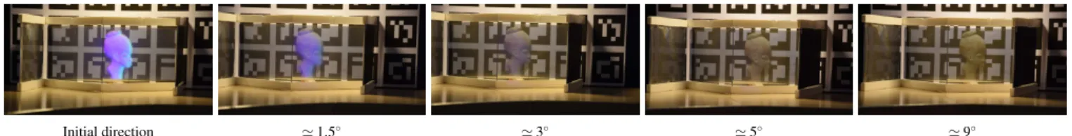
Prototype with indirect retroreflection: Since the prototype of our second setup allows to augment a larger area, we have per-formed more tests, as can be seen in Figures 8 and 1(c). As with the first prototype, we can see both the object by transparency and the augmentation, and we can also add annotations.
It is easier to observe the retroreflective property with such a setup. In this purpose, we rotate the camera around the object by moving away from the original view direction (i.e., the projection direction). When aligned, the augmentation intensity is at the max-imum, as can be seen in Figure 9. After 3◦, the augmentation has
almost disappeared, as confirmed by [10]. This is the expected be-havior. Moreover, it shows that we do not need to be perfectly aligned to see the augmentation, and this leads to some flexibilities in designing the setup.
In our current prototype, some light ghost images can be noticed (see Figure 10). Our investigations have shown us that this is due to the optical properties of the one-way mirror film that we use as a beam splitter: it has a non-negligeable diffuse part. This is confirmed by the fact that such a ghost image does not appear when using a pure mirror or a pure transparent glass. This is one of the directions that we want to improve in the future.
About the two scenarios: as explained above, the personalized multi-user experience with both scenarios is naturally handled with the two prototypes. Since the retroreflective material reflects within a small cone around the perfectly retroreflective path, the retrore-flective behavior is still present even when the viewpoint is only quasi-aligned with the projector and the object (Figure 11). This makes it possible that multiple users can see the augmentation. Requirements for the retroreflectivity: All these tests show that the core component of our setups, the retroreflectivity, must be im-proved. An ideal behaviour would have the following properties.
Initial direction ≃ 2.5◦ ≃ 5◦ ≃ 7.5◦
Figure 10: Illustration of the ghost image when the viewing di-rection varies compared to the projection didi-rection: a fixed image appears in the beam splitter. This appears in some particular condi-tions for the indirect retroreflection implementation.
≃ −6.5◦ Initial direction ≃ 6.5◦ ≃ 15◦
Figure 11: In each image, the projector is fixed at a distance of 1.5m of the retroreflective material, and the viewpoint is at a dis-tance of 5.5m. From left to right, the horizontal disdis-tance between the projector and the viewpoint is -60cm, 0cm, 60cm, and 150cm. In this example, at least 3 people can see the same augmentation. (i) The retroreflective material and the beam-splitter have to be as less diffuse as possible. We still have to investigate such a material. (ii) A ”non-perfect” retroreflective part enables some flexibilities in the alignment of the users and the projectors. This is currently the case with most of the commercialized materials.
(iii) The prisms of the retroreflective material have to be smaller in order to improve the ratio transparency/retroreflectivity. Going to nano-sized particles may also make it possible to create a material able to retroreflect a reduced set of wavelengts that would be used for the projection systems and transmit the other visible wavelengts.
6 CONCLUSION
We introduced EgoSAR, a new SAR approach that makes it possi-ble to have a personalized experience in a multi-user environment. We obtain the personalized experience by exploiting the proximity of users to projectors that create the augmentations on a retrore-flective material. The users that are quasi-aligned with a projector receive the respective light from the projector and thus see the aug-mentation. In addition to the augmentation, all users can also see the real-world scene, because we combine the light path from the augmentation and the light path from the real-world scene.
We presented two prototype implementations of EgoSAR. The first one uses direct retroreflection on a perforated and thus semi-transparent retroreflective film that is put on a glass pane, and the second one uses indirect retroreflection with a beam splitter. We have shown that both prototype implementations validate our ap-proach. However, we know that these prototypes are improvable. For the first approach, this is mainly due to the fact that we did not find an appropriate off-the-shelf semi-transparent retroreflective material, and so we had to produce this type of material ourselves. We are optimistic that this type of material will be further improved in future, for example with very small prisms that could be created with nanotechnology.
From an application point of view, we have shown two scenarios that offer a high potential for our approach. A first active scenario relies on lightweight projectors that users wear or carry. With these projectors, several tracked users can participate to a personalized experience in multi-user environments. Again, we believe that the evolution of the tracking and projection technology (latency, bright-ness, resolution) will further push our approach. A second passive scenario does not even require the users to wear or carry anything,
Initial direction ≃ 1.5◦ ≃ 3◦ ≃ 5◦ ≃ 9◦
Figure 9: Indirect retroreflection - Evolution of the augmentation with respect to the viewing angle (relatively to the projected direction). but to stand or sit on designated locations where a personalized
augmentation happens. Note that in both cases, the personalized augmentation can also be mixed with classical SAR by putting a wide-angle projector inside the showcase.
Besides improving the involved materials and creating first us-able applications, there are various avenues for future work. We have made some encouraging tests with polarized light in order to reduce some residual images that could be projected onto the real object. Moreover, the augmentation is currently done on a material that is situated in front of the object, and so it is planar, even when it is imaged behind the material as in our second approach. We would like to investigate how to create a non-planar floating augmentation that adjusts to the geometry of the objects to augment, while main-taining the personalized experience in multi-user environments.
REFERENCES
[1] K. Aks¸it, D. Kade, O. ¨Ozcan, and H. ¨Urey. Head-worn mixed reality projection display application. In Proc. of the 11th Conference on Ad-vances in Computer Entertainment Technology, page 11. ACM, 2014. [2] A. Butler, O. Hilliges, S. Izadi, S. Hodges, D. Molyneaux, D. Kim, and D. Kong. Vermeer: direct interaction with a 360 viewable 3d display. In Proc. of ACM UIST 2011, pages 569–576. ACM, 2011. [3] castAR. castAR website. http://castar.com/, 2016.
Ac-cessed: 2016-02-11.
[4] A. Ferscha and M. Keller. Digiscope: an invisible worlds window. In Ubicomp 2003, pages 261–264, 2003.
[5] S. Garrido-Jurado, R. Muoz-Salinas, F. Madrid-Cuevas, and M. Marn-Jimnez. Automatic generation and detection of highly reliable fiducial markers under occlusion. Pattern Recognition, 47(6):2280 – 2292, 2014.
[6] N. S. Holliman, N. Dodgson, G. E. Favalora, L. Pockett, et al. Three-dimensional displays: a review and applications analysis. Broadcast-ing, IEEE Transactions on, 57(2):362–371, 2011.
[7] H. Hua, L. E. Brown, and C. Gao. System and interface framework for scape as a collaborative infrastructure. Presence, 13(2):234–250, 2004.
[8] H. Hua, C. Gao, F. Biocca, and J. P. Rolland. An ultra-light and com-pact design and implementation of head-mounted projective displays. In Virtual Reality, 2001. Proc. IEEE, pages 175–182. IEEE, 2001. [9] H. Hua, C. Gao, L. D. Brown, N. Ahuja, and J. P. Rolland. A
testbed for precise registration, natural occlusion and interaction in an augmented environment using a head-mounted projective display (HMPD). In Virtual Reality, 2002. Proc. IEEE, pages 81–89. IEEE. [10] H. Hua, A. Girardot, C. Gao, and J. P. Rolland. Engineering of
head-mounted projective displays. Applied Optics, 39(22):3814–3824, 2000.
[11] M. Inami, N. Kawakami, D. Sekiguchi, Y. Yanagida, T. Maeda, and S. Tachi. Visuo-haptic display using head-mounted projector. In Vir-tual Reality, 2000. Proc. IEEE, pages 233–240. IEEE, 2000. [12] A. Jones, K. Nagano, J. Liu, J. Busch, X. Yu, M. Bolas, and
P. Debevec. Interpolating vertical parallax for an autostereoscopic three-dimensional projector array. Journal of Electronic Imaging, 23(1):011005, 2014.
[13] A. Jones, J. Unger, K. Nagano, J. Busch, X. Yu, H.-Y. Peng, O. Alexander, M. Bolas, and P. Debevec. An automultiscopic pro-jector array for interactive digital humans. In ACM SIGGRAPH 2015 Emerging Technologies, SIGGRAPH ’15, pages 6:1–6:1. ACM, 2015. [14] J. Jurik, A. Jones, M. Bolas, and P. Debevec. Prototyping a light field display involving direct observation of a video projector array. In CVPRW, pages 15–20. IEEE, 2011.
[15] A. Karnik, W. Mayol-Cuevas, and S. Subramanian. Mustard: A multi user see through ar display. In Proc. of CHI 2012, pages 2541–2550. [16] D. M. Krum, E. A. Suma, and M. Bolas. Augmented reality using
per-sonal projection and retroreflection. Perper-sonal and Ubiquitous Com-puting, 16(1):17–26, 2012.
[17] D. Martinez Plasencia, F. Berthaut, A. Karnik, and S. Subramanian. Through the combining glass. In Proc. of UIST 2014, pages 341–350. [18] R. Miyake, H. Zeman, F. Duarte, R. E. Kikuchi R., L. G., and V. C. Vein imaging: a new method of near infrared imaging, where a pro-cessed image is projected onto the skin for the enhancement of vein treatment. Dermatol Surg., 32(8):1031–1038, 2006.
[19] E. Moon, S.-W. Park, H. Chung, J.-Y. Lee, C. Bae, J.-W. Kim, J. Paek, and H. Kim. Truncated corner cubes with near-perfect retroreflection efficiency. Applied optics, 53(33):7972–7978, 2014.
[20] D. Moreno and G. Taubin. Simple, accurate, and robust projector-camera calibration. In Proc. of 3DIMPVT 2012, pages 464–471, 2012. [21] A. Nee, S. Ong, G. Chryssolouris, and D. Mourtzis. Augmented reality applications in design and manufacturing. CIRP Annals-Manufacturing Technology, 61(2):657–679, 2012.
[22] H. Nii. Wide area projection method for active-shuttered real image autostereoscopy. In ACM SIGGRAPH 2013 Posters, page 53:1. [23] A. Olwal, C. Lindfors, J. Gustafsson, T. Kjellberg, and L. Mattsson.
Astor: An autostereoscopic optical see-through augmented reality sys-tem. In Proc. of the 4th IEEE/ACM ISMAR ’05’, pages 24–27. [24] M. Perry, S. Beckett, K. O’Hara, and S. Subramanian. Wavewindow:
Public, performative gestural interaction. In ACM Interactive Table-tops and Surfaces, ITS ’10, pages 109–112. ACM, 2010.
[25] R. Raskar, G. Welch, M. Cutts, A. Lake, L. Stesin, and H. Fuchs. The office of the future: A unified approach to image-based modeling and spatially immersive displays. In Proc. of SIGGRAPH ’98, pages 179– 188.
[26] R. Raskar, G. Welch, and H. Fuchs. Spatially augmented reality. In In First IEEE Workshop on Augmented Reality, pages 11–20, 1998. [27] B. Ridel, P. Reuter, J. Laviole, N. Mellado, N. Couture, and
X. Granier. The revealing flashlight: Interactive spatial augmented reality for detail exploration of cultural heritage artifacts. J. Comput. Cult. Herit., 7(2):6:1–6:18, June 2014.
[28] Y. Tokuda, A. Hiyama, M. Hirose, and H. Yamamoto. R2d2 w/ AIRR: Real time & real space double-layered display with aerial imaging by retro-reflection. In SIGGRAPH Asia 2015 Emerging Technologies, pages 20:1–20:3. ACM, 2015.
[29] Y. Ueda, N. Hanamitsu, Y. Mizushina, M. Shibasaki, K. Minamizawa, H. Nii, and S. Tachi. Haptomirage: A multi-user autostereoscopic visio-haptic display. In ACM SIGGRAPH 2013 Posters, page 73:1. [30] O. Wang, M. Fuchs, C. Fuchs, J. Davis, H.-P. Seidel, and H. P. Lensch.
A context-aware light source. In IEEE International Conference on Computational Photography, April 2010.
[31] K. D. D. Willis, T. Shiratori, and M. Mahler. Hideout: Mobile pro-jector interaction with tangible objects and surfaces. In Proc. of TEI 2013, pages 331–338. ACM, 2013.
[32] A. D. Wilson. Touchlight: An imaging touch screen and display for gesture-based interaction. In Proc. of the 6th International Conference on Multimodal Interfaces, ICMI ’04, pages 69–76. ACM, 2004. [33] H. Yamamoto, Y. Tomiyama, and S. Suyama. Floating aerial LED
signage based on aerial imaging by retro-reflection (AIRR). Optics express, 22(22):26919–26924, 2014.
[34] T. Yoshida, K. Shimizu, T. Kurogi, S. Kamuro, K. Minamizawa, H. Nii, and S. Tachi. Repro3d: full-parallax 3d display with haptic feedback using retro-reflective projection technology. In VR Innova-tion (ISVRI), 2011 IEEE InternaInnova-tional Symposium on, pages 49–54.