Publisher’s version / Version de l'éditeur:
Vous avez des questions? Nous pouvons vous aider. Pour communiquer directement avec un auteur, consultez la première page de la revue dans laquelle son article a été publié afin de trouver ses coordonnées. Si vous n’arrivez pas à les repérer, communiquez avec nous à [email protected].
Questions? Contact the NRC Publications Archive team at
[email protected]. If you wish to email the authors directly, please see the first page of the publication for their contact information.
https://publications-cnrc.canada.ca/fra/droits
L’accès à ce site Web et l’utilisation de son contenu sont assujettis aux conditions présentées dans le site LISEZ CES CONDITIONS ATTENTIVEMENT AVANT D’UTILISER CE SITE WEB.
Proceedings of the 3rd International Energy Agency Heat Pump Conference, pp.
443-453, 1990-03-12
READ THESE TERMS AND CONDITIONS CAREFULLY BEFORE USING THIS WEBSITE. https://nrc-publications.canada.ca/eng/copyright
NRC Publications Archive Record / Notice des Archives des publications du CNRC :
https://nrc-publications.canada.ca/eng/view/object/?id=d9e93bc8-26c7-4a22-842e-0c5c178b0eca
https://publications-cnrc.canada.ca/fra/voir/objet/?id=d9e93bc8-26c7-4a22-842e-0c5c178b0eca
NRC Publications Archive
Archives des publications du CNRC
This publication could be one of several versions: author’s original, accepted manuscript or the publisher’s version. / La version de cette publication peut être l’une des suivantes : la version prépublication de l’auteur, la version acceptée du manuscrit ou la version de l’éditeur.
Access and use of this website and the material on it are subject to the Terms and Conditions set forth at
Spiral ground heat exchangers for heat pump applications
R e f
T H 1
N 2 1 d
+r(
Natlonal Research
Council Canada
ConseI
de racherches Canada
national
n. 1685
1 9 9 0
'
Institute for
lnstitut de
B L D G .
Research in
recherche en
- -.+ . - -
Construction
construction
IKC PUB
Spiral Ground Heat Exchangers
- - -
for Heat Pump Applications
by Otto J. Svec
/I'ANALYZED
Reprinted from
Proceedings of the 3rd International Energy Agency
Heat Pump Conference, Tokyo, Japan
12-15 March, 1990
pp. 443-453
(IRC Paper No. 1685)
NRCC 32355
N R C-
ClSTl %+I R C
- + % >L I B R A R Y
-$
* > iAPR
25
1991
'.
B I B L I O T H ~ Q U E
I R C
CNRC-
IClST-
+ _
ResumC
Ce document dCait un nouveau systeme horizontal d'echange de chaleur sur
sol utilid dans une installation exp6rimentale de pompe B chaleur captage
au sol (PCCS).
Le
principe consiste
B
activer une grande masse de sol en
employant de gros 6changeurs de chaleur B spirale (pouvant atteindre
60 an)
faits de tubes de cuivre ou de polybthylene haute densite. Le systhme a Ct6
contr8lC au cours de l'hiver
1988-1989,
et sa performance s'est r6vCl&
excellente. Les rbultats obtenus alors et notre experience indiquent qu'il est
possible de faire des konomies substantielles sur les coots initiaux
&installation.
Il
se peut en outre que ces systemes horizontaux soient dans la
plupart des cas plus bnomiques que les systhmes verticaux de PCCS.
+ .
*Spiral Ground Heat Exchangers for
Heat Pump Applications
Otto J. Svec
I n s t i t u t e f o r Research i n Construction National Research Council of Canada
Ottawa, Ontario, KIA OR6, Canada
ABSTRACT
T h i s paper describes a novel horizontal ground heat exchange system uaed i n
an
e x p e r h a n t a l Ground Source Beat Pump (GSES) i n s t a l l a t i o n , The b a s i c concept i at o
a c t i v a t e a large mass o f s o i l b y employing"largen ( u p to 60 cm) s p i r a l heat exchangers made of copper and high density pclyethylene tubing. The results o f monitoring the system during the 198&/$9 winter season demonstrate its excellent performance. I n addition, t h e s e r e s u l t s together with o u r experience,
i n d i c a t e t h a t Large p o t e n t i a l savings on i n i t i a l i n s t a l l a t i o n c o a t s a r e possible. Moreover, s u c h horizontal systems may be
more
economical t h a n v e r t i c a l GSHP systems i n most p r a c t i c a l s i t u a t i o n s .KEYWORDS
Heat pump, ground, heat exchanger, s p i r a l
,
1) IntroductionThe GSBP system is recognized as the moat successful
of
all renewableenergy technologies i n most Northern European a n d North American
* c o u n t r i e s . The GSRPrs high initial cost i s t h e only factor slowing
-
down its wide-spread penetration i n t o the marketplace. A l a r g e p a r t o f t h i s cost, e . 30-40% landi n
some casea sven more), i e associated with t h e i n s t a l l a t i o n of ground heat exchange systems.The main
objectiveof
t h e research program a t the Institute f o rResearch i n
Construction,N a t i o n a l
Research Council Canada (IRC/NRC)- has been t o develop a highly efficient ground heat exchanger. The
goal has bean t o reduce t h e xequired length of a ground c o l l e c t o r
through improved e f f i c i e n c y , and t h e r e f o r e
t o
lower t h e o v e r a l l coat of GSHPs. Efforts have been successful and t h e ground hest exchanga technology developedin
IRC/NRC I s now ready t o be t r a n s f e r r e d t o t h e GSHP industry.2 ) The NRC Ground Heat Exchanaer
Research work a t IRC/NRC, which p r o g r e s s e d from l a b o r a t o r y s t u d i e s , Ref. 1, t h r o u g h t e s t i n g p r o t o t y p e s i n t h e f i e l d , R e f s . 2,3, and
.
f i n a l l y t o a f u l l s c a l e t e s t i n g of GSHP systems i n two e x p e r i m e n t a l houses, Ref. 4 , r e s u l t e d i n a new ground h e a t exchanger d e s i g n . I t s T- main f e a t u r e i s t h e s p i r a l shape of t h e h e a t exchanger i t s e l f and a s t r a i g h t t u b e r e t u r n , F i g 1.BACKFILL
SAND
PLASTIC
33
mrn
D!A150-1 80
m m
F i g . 1. H o r i z o n t a l S p i r a l Ground Heat Exchanger I n s t a l l e d I n A D i t c h
Such a heat exchanger can perfoxm well,
i n
both vertical and r h o r i z o n t a l c o n f i g u r a t i o n s . I n this paper, o n l y t h e performance of t h e h o r i z o n t a l c o p p e r and p l a s t i c s p i r a l heat e x c h a n g e r s i a d e s c r i b e d . T h i s t e c h n o l o g y has been d e v e l o p e d t o such a degree,p a r t i c u l a r l y the plastic
60 cm
( 2 4 " ) s p i r a l , t h a t it can be r e a d i l ymanufactuxed a n d used
i n c o m e r c i a l
a p p l i c a t i o n s p r a c t i c a l l y w i t h o u t - modifications. The s i m p l i c i t y of i t s d e s i g n and i n s t a l l a t i o n t e c h n i q u e should make this ground h e a t c o l l e c t o r technique superior.
t o any o t h e r c u r r e n t l y i n use.There a r e s e v e r a l key a d v a n t a g e s o f t h e s p i r a l d e s i g n :
*
t h e t h e r m a l i n t e r a c t i o n between t h e " I N " l o o p ( s p i r a l ) and t h e*
t h e h e a t exchange s u r f a c e i s always a t t h e o u t s i d e b o u n d a r i e s o f t h e d i t c h , s o t h a t t h e e f f e c t i v e s u r f a c ei s
a c y l i n d e r 60 c m (24") i n diameter:*
t h e s p i r a l a c t s a s a s p r i n g and t h u s can b e s t r e t c h e d t o any d e s i r e d s p a c i n g , i . e . a d e s i g n e r c a n choose t h e h e a t e x t r a c t i o n i n t e n s i t y :*
iti s
v e r y e a s y t o i n s t a l l : a l l t h a ti s
needed i s t o s t r e t c h t h e c o l l a p s e d c o i l and t h e n t o b a c k f i l l :*
t h e geometry of t h e s p i r a l i s a u t o m a t i c a l l y a s s u r e d by t h e c o i l i t s e l f :*
t h e e n t i r e i n s t a l l a t i o n of t h e ground h e a t c o l l e c t o r c a n b e completed by o n l y one p e r s o n ( p l u s t h e back-hoe o p e r a t o r ) ;*
b o t h t h e copper and p o l y e t h y l e n e s p i r a l s a r e s t r o n g enough t o a l l o w e a s y and e f f e c t i v e b a c k f i l l i n g ( p a r t i c u l a r l y w i t h s a n d ) ;*
o n l y one c o n n e c t i o n i s needed a t t h e end of t h e d i t c h .The o n l y d i s a d v a n t a g e s o f a r e x p e r i e n c e d ,
i s
t h e p o s s i b i l i t y o f a i r c o l l e c t i o n a t t h e t o p of t h e s p i r a l l o o p s . However, b y u s i n g an o v e r s i z e d pump a t t h e t i m e of f i l l i n g and c a r e f u l l y d e a e r a t i n g t h e system, t h i s problem can b e overcome.3 ) E x p e r i m e n t a l S e t u p
I n t h e f a l l o f 1988 l a r g e h o r i z o n t a l copper and h i g h d e n s i t y p o l y e t h y l e n e s p i r a l h e a t e x c h a n g e r s were i n s t a l l e d a s p a r t of a
5.25 kW GSHP system. These s p i r a l c o i l s were f a b r i c a t e d s p e c i a l l y f o r t h i s p r o j e c t by copper and p l a s t i c t u b e m a n u f a c t u r e r s . There were no d i f f i c u l t problems e n c o u n t e r e d i n t h e f a b r i c a t i o n p r o c e s s . The s p e c i f i c a t i o n s f o r t h e s e h e a t e x c h a n g e r s a r e a s f o l l o w s : T a b l e I . S p e c i f i c a t i o n s Of Heat Exchangers M a t e r i a l Tubing S p i r a l S i z e S p i r a l P i t c h Copper 2 . 2 cm (7/811) 60 cm (24") 12
cm
(8") P o l y e t h y l e n e 3 . 3 cm (1.31") 45 cm (18) 1 2 cm ( 8 " )Three h e a t e x c h a n g e r s were i n s t a l l e d : two copper s p i r a l s e a c h i n a 4.9 m ( 1 6 ' ) l o n g d i t c h and one p l a s t i c s p i r a l i n a 9.8 m (32' ) l o n g d i t c h . The t o t a l l e n g t h , t h e r e f o r e , was 19.5
m
( 6 4 ' ) i n t e r m s of t h e d i t c h . T h i s r e p r e s e n t s l / l O t h o r 1 / 6 t h of t h e s t a n d a r d d e s i g n depending on one o r two t u b e s i n a d i t c h , r e s p e c t i v e l y . A l l t h r e e h e a t e x c h a n g e r s were i n s t a l l e d i n a 1 . 8 m ( 6 ' ) deep d i t c h e x c a v a t e d i n l e d a c l a y s o i l and b a c k f i l l e d up t o t h e t o p of t h e s p i r a l s w i t h sand, F i g . 1. A m i x t u r e of water/methanol was u s e d a s t h e h e a t c a r r y i n g f l u i d . T h i s system was h e a t i n g a 90 m2 e x p e r i m e n t a l onestorey house, i.e.
90m2 on the main floor and the same area in the
basement, during the
1988/89winter season without any backup. The
indoor temperature was kept constant at
2Z°C.
The main objective of
this experiment was to determine the heat extraction rates for these
-coils operating at subfreezing temperatures.
w4)
Monitorina Of Svstem Performance
The detsrmination of the
system performance
iabaeed
onmonitoring
the
extracted energyfrom
theground, energy used to run the heat
pump and the energy consumed by
t h ecirculation
pwrrp.In addition,
the behavior
of the system during individual cycle8 is being
nbserved,
aswell
as
theground thermal depletion and its
recharging.
The
aystem has been monitored at approximately
15second intervals
durkng
each running
cycle.
Acomputer program
isinitiated
by theimpulse from the thermostat
as it demands heating
orcooling. The
inlet
andoutlet
temperature
of
the
circulating
fluid
(water/methanol) is
measured
at
the distribution manifold
in the
basement of the house for each heat exchanger separately, and as
well, for the system as a whole. There are two thermistors in each
location. The overall accuracy of these sensors is
2
0.005°C.The
accuracy of the fluid flow meters is about
1-
2%.After each cycle,
readinga are sufianarisedand the
average differenceo f
the inlet and the outlet
temperatures i scomputed. This
information, together with fluid
flow (accumulated volume), is used
to calculate gained
or dissipatedenergy
byeach ground loop,
a nwell
as
bythe entire system.
Daily,weekly,
andmonthly energy balances
are determined. In order
to
aassssthe overall performance
o findividual
heat exchangezer
theheat energy extraction
orrejection
per
meter of
theditch
i saleo
calculated.5)
Results
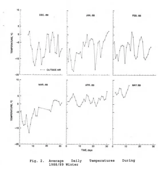
The average daily outside air temperatures from December to April are
shown in Fig.
2for reference purposes. The data points represent
daily average temperatures measured at
20minute intervals.
The most significant result of this study is that by using large
spiral heat exchangers, high rates of heat extraction, E,, from the
ground can be obtained, Table
11.Table 11. Heat Extraction Rates
(Ex)in Watts per meter of
the ditch, Coefficient of Performance (COP) and
water return temperatures (T,)
,
during
1988/89winter season
*...
E x
E"
E x E xMonth Plastic Copper
Copper
System
COP
T.
- -
Dec
.
140
170 165 158 2.55 -0.9Jan.
130 155 155 148 2.45 -3.0Feb
.
120 145 145 137 2.40 -3.8Mar.
125 153 155 144 2.35 -3.8Apr
.
125 170 160 152 2.35 -1.7As
expected, the copper apirala performed better than the plastic
ones due to
thehighex thermal conductivity of the copper. It should
be noted, however, that the contact (heat exchange) area between the
tube and
thesoil was
7.0cmf/cm for copper and 10.5
cmi/em fox.
-plastic, i.e.
L . 5 : l . O r a t i oin favor of plastic tube. The linear
length of the tubes per meter of the ditch far copper and plastic
spirals was
approximately the
same.Yet,
because
the.copper spirals
had larger outside diameter than the plastic spirals, i.e.
60 cm
-
versus
45cm, the former activated a larger soil maas. Therefore the
comparison between these two spiral
heat exchangers
is based
on
three
variables: material, (copper versus plastic), tube diameter
(2.2
cmversus 3.34 cm)
and spiral
diameter(45
crnversus 60 cm), Table
I.In spite of
thesedifferences, the comparison is realistic, since
twopractical designs based on coneiderations such
aacost, manufacturing
process, handling etc.
are compared.Horeovex, it
is expected that
the future design
o feither plastic or copper spiral
heat exchangers
will not significantly differ from those used in this project.
In surmnary, the significance of the results presented in Table I1 is
two-f
old:
a)
the heat extraction rates are very high and
b)
the difference between the heat extraction rates for copper and
plastic spirals is not as large as expected.
Economic and practical considerations will determine whether copper
or plastic spirals will be used in commercial installations. In the
author's opinion, large (60 cm) spirals made from high density
polyethylene tubing,
3.3-
4.0 cm in outside diameter, will be the
most practical choice.
Variations in heat extraction rates during the winter season are
shown in Fig.
3.These results for the months of December, February
and April represent typical behavior of the ground heat exchangers.
The important aspect here is the magnitude of energy withdrawn from
the ground.
Another
set
o fdata, presented
in Fig. 4 shows temperature
differences,
dT, between the " I N nend
the "OUTwtubes
ofall three
heat
exchangers during December, February and April.
Itcan
beobserved that this diiference (except
i nApril) is
largest for the
plastic spiral.
This
resultcan
beattributed to the
f a c tthat the
length
of the plastic spiral is
t w i c eas
longas the copper
one.The overall dT for the entire ground heat exchange system during
December, February and April is shown on Fig.
5.The significance of
these results is that even though the absolute temperature of the
circulating fluid decreases with increasing heating demand and ground,
thermal depletion, the dT remains constant
-
approximately 2OC.
The Coefficient of Performance (COP), see Table 11, was lower than
would be required in a commercial installation, but, considering the
short length of the ground heat exchangers, the COP was still better
than expected. The objective
o f thisproject was
tod e t e d n e the
performance of prototypes of new ground heat exehangars,
i . e ,large
horizontal spirals, and namely the rate of heat exchange during a
normal winter operation. The objective
wasnot
to design sn efficientGSHP symtem. In fact the
ground
heat collector was purposely
DEC. i88 JAN. /@a
1
o-o OUTSIDE AIR-2sL-, ' , , , , , ,
l5
[
MAR. 109 APR. W8 M Y M
Fig. 2. Average Daily Temperatures During 1988/89 Winter
t h i s p e r s p e c t i v e . The COP i s , however, v e r y r e s p e c t a b l e f o r such a s m a l l ground h e a t exchange system. A s mentioned above, t h e t o t a l l e n g t h of t h e ground h e a t exchange s y s t e m ( i n
terms
of r e q u i r e d d i t c h ) was o n l y a f r a c t i o n of what i s c u r r e n t l y b e i n g u s e d by t h e.
GSHP i n d u s t r y .
As c o u l d be e x p e c t e d , t h e COP d e c r e a s e d w i t h d e c r e a s i n g c i r c u l a t i n g f l u e d t e m p e r a t u r e , Table 11. The d e o r e a e e of t h e e n t e r i n g -
_
w a t e r h e t h a n a l t e m p e r a t u r e from O°C a t t h e b e g i n n i n g o fDecember
t o-5.5'C i n t h e m i d d l e
of
March, r e s u l t e di n
about a 1 0 % decrease of!-
COP. Thia is o n l y a modest l o s s , one which might be lowered by
o p t i m i z i n g t h e e n t i r e system.
6) Conclusion
*
Large d i a m e t e r s p i r a l h o r i z o n t a l copper and p l a s t i c h e a t e x c h a n g e r s have been developed, c o n s t r u c t e d and t e s t e d i n a r e a l f i e l d i n s t a l l a t i o n . No d i f f i c u l t i e s were e n c o u n t e r e d i n t h e f a b r i c a t i o n p r o c e s s and no problems were e x p e r i e n c e d i n t h e i n s t a l l a t i o n . The i n s t a l l a t i o n p r o c e s s proved t o b e s i m p l e , f a s t and i n e x p e n s i v e . I n f a c t , t h e e n t i r e ground h e a t exchange system u s i n g e i t h e r copper o r p l a s t i c s p i r a l s c a n b e i n s t a l l e d e a s i l y by o n l y one p e r s o n ( p l u s an o p e r a t o r f o r t h e e x c a v a t i o n machine).
Beat e x t r a c t i o n r e s u l t s a r e v e r y good. Due
t o
t h e expected low c o s tof t h e h e a t exchangers, the s i m p l i c i t y o f t h e i r i n s t a l l a t i o n , a n d t h e i r h i g h performance, t h i a
new
ground h e a t exchange t e c h n o l o g y w i l ldecrease t h e initial cost of GSBPrs i n g e n e r a l . It i s expected that
GSHP'B u t i l i z i n g t h e s e
new
ground h e a t e x c h a n g e r s will becomec o m p e t i t i v e i n t h e h e a t i n g / c o e l i n q market.
T h i s new t e c h n o l o g y ( p a r t i c u l a r l y t h e p l a s t i c s p i r a l s )
is
a t t h e s t a g e whereit
c a n be adopted e a s i l y by t h e GSHP i n d u s t r y . Manufacturers of p l a s t i c tubing have t o be found, who are p r e p a r e d t oproduce s t a n d a r d 6Ocm/3.34cm (24"/1.31") s p i r a l / t u b i n g coils. T h e I n i t i a l r e s p o n s e from a few m a n u f a c t u r e r s i n Canada was p o s i t i v e : no major problems associated w i t h t h e m a n u f a c t u r i n g p r o c e s s are
e x p e c t e d .
REFERENCES
Svec, O . J . , L.E. Eoodrlch a n d J.A.L. Palmer (1983).
Heat
t r a n s f e r c h a r a c t e r i s t i c 0 of in-ground heat e x c h a n g e r s . Energy Research,V O ~ . 7, p.265-278. (NRCC 2 2 6 7 4 )
Svec, O . J . I L 9 B 5 ) . P o t e n t i a l f o r improvement between ground and h e a t pump energy exchange, Proceedings, Second Workshop on Solar
A s s i s t e d Heat Pumps w i t h Ground Coupled S t o r a g e , Vienna, A u s t r i a ,
July 1985, p 4 3 1 - 4 4 0 . (NRCC 27413)
Svec, O.J. and Palmer J.H.L. (1989). Performance of a s p i r a l ground
heat-exchanger f o r heat pump a p p l i c a t i o n .
Int.
Journal o f E n e r g y ' -Research, V o l 13, p . 503-510.. d
Svec, 0. J. (1988 1
.
Spiral h e a t exchangers-
Demonstration o fa
new.
ground s o u r c e h e a t pump t e c h n a l o g y . Proceedings, Jfgastock 88,ACKNOWLEDGEMENTS
The author wishes to express his gratitude to Dr. J.H.L. Palmer of
.
IRC/NRC for many inspiring discussions, to Messrs. D. Eldred and
D. MacMillan for their excellent technical assistance and to
Mr.Mike
?
Wiggin of the Department of Energy Mines and Resources, CANMET
This
paper is being distributed in reprint form by the Institute for Research in Construction. A list of building practice and research publications available from the Institute may be obtained by writing to Publications Section, Institute for Research in Construction, National Research Council of Canada, Ottawa, Ontario,KIA
0R6.Ce document est distribue sous forme de tir&&-part par I'Institut de recherche en construction. On peut obtenir une liste des publications de I'Institut portant sur les techniques ou les recherches en mati* de bgtiment en krivant B la Section des publications, Institut de recherche en construction, Conseil national de