HAL Id: hal-00846054
https://hal.archives-ouvertes.fr/hal-00846054
Submitted on 19 Jul 2013
HAL is a multi-disciplinary open access archive for the deposit and dissemination of sci-entific research documents, whether they are pub-lished or not. The documents may come from teaching and research institutions in France or abroad, or from public or private research centers.
L’archive ouverte pluridisciplinaire HAL, est destinée au dépôt et à la diffusion de documents scientifiques de niveau recherche, publiés ou non, émanant des établissements d’enseignement et de recherche français ou étrangers, des laboratoires publics ou privés.
Stick-slip instabilities in the shear flow of
magnetorheological suspensions
Modesto Lopez-Lopez, Pavel Kuzhir, Laura Rodriguez Arco, Jaime Caballero
Fernandez, Juan D. G. Durán, Georges Bossis
To cite this version:
Modesto Lopez-Lopez, Pavel Kuzhir, Laura Rodriguez Arco, Jaime Caballero Fernandez, Juan D. G. Durán, et al.. Stick-slip instabilities in the shear flow of magnetorheological suspensions. Journal of Rheology, American Institute of Physics, 2013, 57 (4), pp.1101. �10.1122/1.4804358�. �hal-00846054�
1
Stick-slip instabilities in the shear flow of magnetorheological suspensions
Modesto T. López-López,1 Pavel Kuzhir,2 Laura Rodríguez -Arco1,
Jaime Caballero-Hernández,1 Juan D. G. Durán,1 and Georges Bossis2
1 Departamento de Física Aplicada, Facultad de Ciencias, Universidad de Granada, Campus de Fuentenueva,
18071 Granada, Spain
2
Université de Nice Sophia Antipolis, Laboratoire de Physique de la Matière Condensée, CNRS UMR 7336, Parc Valrose, 06108 Nice cedex 2, France
Synopsys
This work is devoted to the stick-slip instabilities that appear in the shear flow of highly
concentrated suspensions of magnetic microparticles. The effect of the applied magnetic field
strength was analyzed in details. With this aim, homogeneous suspensions of iron
microparticles with concentration near the limit of maximum-packing fraction were prepared,
and shear-flow measurements were performed in a controlled-rate mode using a rheometer
provided with a rough parallel-plate geometry. For each given value of the shear rate, the time
evolution of the shear stress was monitored for at least 20 min. Saw-tooth-like stress
oscillations, typical of stick-slip instabilities, were obtained at low enough shear rate values.
The measurements were restricted to small enough oscillations, at which the rheometer was
still able to maintain the shear rate constant. From the microscopic viewpoint, these stick-slip
instabilities principally appear due to the periodic failure and healing of the field-induced
particle structures, as inferred from experimental observations. This hypothesis is
corroborated by a theoretical model developed on the basis of the balance of the magnetic and
hydrodynamic torques over the particle structures, allows us to predict the correct order of
magnitude of the main parameters of the stick-slip instabilities, including the amplitude and
2
I. INTRODUCTION
The behavior of yield stress fluids in the vicinity of the yield point has recently
attracted much attention in literature. Most of the macroscopic measurements performed on
various complex fluids exhibiting a yield stress (concentrated colloidal and granular
suspensions, emulsions and micelle solutions, polymer liquids and polymer blends) have
shown that a stable steady-state flow is impossible for these fluids at small enough shear rates
[Bécu et al. (2006); Bonn et al. (2002); Coussot et al. (2002); Da Cruz et al. (2002); Huang et
al. (2005); Jarny et al. (2005); Ovarlez et al. (2006); Ragouilliaux et al. (2007); Rodts et al.
(2005); Varadan and Solomon (2003)]. In most cases, the flow curves of these fluids possess
an initial section where the stress either decreases or remains quasi-constant with the shear
rate – the section where flow instabilities occur. These instabilities are manifested through a
loss in the homogeneity of the flow and the deformation fields, which, in many cases, is
accompanied by oscillations of the shear stress or shear rate.
From the microscopic point of view, slow shear flows are often accompanied with
shear banding and/or phase separation phenomena, as revealed by dynamic light scattering
and magnetic resonance imaging for many types of complex fluids [Coussot et al. (2002);
Coussot et al. (2005); Fall et al. (2009); Huang et al. (2005); Ianni et al. (2008); Ovarlez et al.
(2009)]. According to these works, in the vicinity of the yield point two distinct flow regions
coexist: a non-sheared band, containing a high concentration of solid phase, and a highly
sheared band, containing predominantly liquid phase. In addition to shear banding, periodic
oscillations in the flow behavior at subcritical shear rates have also been reported [Ianni et al.
(2008)]. In the phenomenological model of [Picard et al. (2002)], these oscillations were
3 the unstable flow region at the decreasing branch of the flow curve. The authors used the term “stick-slip” for these oscillations even though solid friction does not appear explicitly in their
theory. From all these previous works, it is clear that the microscopic and macroscopic
behaviors of yield stress fluids must strongly depend on the types of interactions in the fluids,
and investigations in this field are intensively continued.
Some well-known yield stress fluids for which the flow instabilities have been
scarcely investigated are electrorheological (ER) and magnetorheological (MR) suspensions.
In these fluids, interparticle interactions can be tuned over several decades by external electric
and magnetic fields, respectively. One of the pioneer studies concerning flow irregularities in
these fluids was carried out by Klingenberg and Zukosky (1990), who visualized the shear
flow of ER suspensions under electric fields applied perpendicular to the rheometer plates.
These authors reported the existence of gap-spanning particle aggregates that were
continuously ruptured by the shear forces and subsequently reformed by association with the
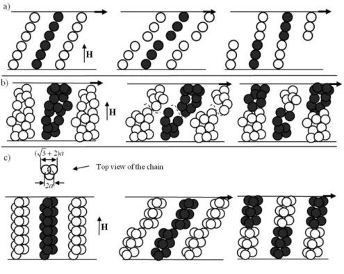
broken parts of the neighboring aggregates. This process is schematized in Fig. 1a. Such
periodic failure and reformation of the structures was later reproduced by particle level
simulations [Klingenberg et al. (1991)]. Bonnecaze and Brady (1992) also performed
simulations of the structure and the stress level in sheared ER fluids and found some
dynamics reminiscent of the stick-slip motion at small shear rates (or rather small Mason
numbers): a slow deformation regime, characterized by the storage of the electrostatic energy,
followed by a rapid release of the energy through viscous dissipation once the aggregates are
ruptured, followed by reformation of the aggregates through associations among broken parts,
as illustrated in Fig. 1b. Both works by Klingenberg et al. (1991) and by Bonnecaze and
Brady (1992) predicted rather irregular stress vs. time responses, with multiple events in
4 The only work reporting explicit experimental stick-slip phenomena in ER
suspensions is, to our knowledge, a short communication by Woestman (1993). This author
measured the strain response of ER fluids to applied stresses using a concentric cylinder cell.
He found that the inner cylinder turned by short jumps (slip) followed by long periods without
distinguishable motion (stick). The resulting stress vs. strain curves showed quite regular
oscillations with a sharp increase of the stress followed by a smooth decrease. Apparently, the
imposed stress was not kept constant but depended on the inertia and stiffness of the
measuring system. Therefore, the quantitative analysis of the observed phenomenon should be
taken with care, while the qualitative interpretation in terms of rupture/reformation remains
reasonable.
FIG. 1. Periodic rupture/reformation processes that may explain the stick-slip phenomenon, for different types of MR structures: (a) single chains of Klingenberg and Zukosky (1990); (b) thick aggregates used in the particle level simulations of Bonnecaze and Brady (1992); (c) triple-chain aggregates used in the present work. Dashed curves in (b) denote rupture locations.
5 In what concerns MR suspensions, the stick-slip instability has been recently reported
for concentrated MR fluids exhibiting a shear thickening behavior [Jiang et al. (2012)]. As
inferred from this short communication, the authors insist on a frictional scenario to explain
the appearance of the stick-slip. They state that the structure evolution of the MR fluid under
low shearing should alter micro-gaps between MR particles, and the lubrication performance
of the suspending liquid is controlled by the external magnetic field, resulting in periodic
transitions between boundary lubrication and hydrodynamic lubrication regimes. Such an
interpretation is somewhat different from the above considered scenario of periodically
breaking and reforming structures. More information about the role of friction forces on the
rheology of ER and MR fluids can be found in [de Vicente and Ramírez (2007), Kuzhir et al.
(2009), Tian et al. (2010-a, 2010-b, 2011), Jiang et al. (2011)].
In view of the lack of experimental studies and of the absence of a common
interpretation of the stick-slip phenomenon in MR suspensions, we have aimed to conduct a
detailed study on stick-slip instabilities. In this manuscript, we focus on the stress response of
highly concentrated MR suspensions subjected to imposed shear rates. Our measurements are
restricted to relatively small oscillations, at which the rheometer is still able to maintain the
imposed shear rate. The experimental oscillating stress signal will be qualitatively compared
with the predictions of the simulations of Klingenberg et al. (1991) and Bonnecaze and Brady
(1992). In addition, we will present our own theoretical model that, as will be shown, predicts
the main features of the stick-slip instabilities observed in our experiments. Finally, we shall
try to estimate whether the flow of our suspension corresponds to lubricated contacts between
6
II. MATERIALS AND METHODS
Carbonyl iron powder (Fe-CC, BASF, Germany), was used as solid phase for the
preparation of the MR suspensions. According to the manufacturer, these particles have
median diameter of 5µm. Mineral oil (density and viscosity at 25 ºC: 0.85 g·cm-3 and 39.58
0.16 mPa·s, respectively) purchased from Sigma Aldrich (Germany) was used as carrier
liquid. MR suspensions with 50 vol.% approximate concentration were prepared following the
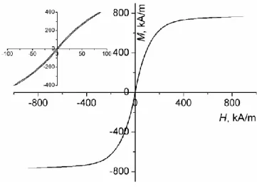
protocol described by López-López et al. (2012). The suspension magnetization was
measured using a hysteresimeter (S2IS, France), and the magnetization curve is plotted in
Fig.2. As is seen in this figure, the suspension remnant magnetization is low as compared to
the saturation magnetization (Mr=6±4 kA/m against MS=760±10 kA/m), and the
magnetization curve appears to be quasi-linear at magnetic fields, H<25 kA/m, with the initial
magnetic susceptibility being equal to i=7.2±0.3. The whole magnetization curve is
satisfactory fitted by a Fröhlich-Kennelly law [Jiles (1991)]: M iM HS /(iHMS).
FIG. 2. Magnetization curve of the MR suspension of volume fraction of 50%. The inset shows the same curve at lower values of the magnetic field.
Rheological measurements were performed at 25 ºC using a rheometer MCR 300
7 parallel plates of 20 mm in diameter, with rough surfaces in order to avoid wall slip. The gap
thickness between the lower (stationary) plate and the upper (rotating) plate was 0.35 mm.
The applied magnetic field was generated with the help of a solenoid, placed co-axially with
the measuring geometry, the technical details being described in Kuzhir et al. (2008).
The experimental protocol used for the rheological measurements was as follows.
Prior to the measurements, the MR sample was intensively stirred by using a mechanical
vortex mixer. Immediately afterwards, the sample was placed in the measuring system of the
rheometer and subjected to a linear shear rate ramp of 1 min of duration in the range 0.1–100
s-1. Then, a magnetic field of a given intensity was applied and the suspension was left at rest
for 30 s. Finally, a constant shear rate (within the range 0.01–200 s-1) was applied during the
time required to achieve shear strains, 1, and the stress response was measured during this time. Once the measurement at a given shear rate was accomplished, the whole process
(starting at the pre-shear stage at zero magnetic field) was repeated at another shear rate. In
this way, each point of the shear stress-vs.-shear rate curve was obtained through a long time
measurement independent on the suspension history at previous shear rates. Presumably,
isotropic structures should constitute the MR suspension before the application of the
magnetic field at each step. As will be shown and discussed below, at low enough shear rates
the shear stress did not reach a steady state value even after 20 min of shearing at constant
shear rate, but instead experienced some regular oscillations with shape very similar to that of
the stick-slip motion of a solid body on a solid substrate. If this was the case, we took the
mean value of the stress (within its oscillations) as the representative stress for the
corresponding shear rate. At this point, it is important to note that the electronic commutation
motor of the rheometer Physica MCR 300 does not allow a perfect control of the strain (or
8 We checked that, at small stress oscillations, the strain signal was almost linear with time.
Consequently, we restricted our measurements to relatively weak stress oscillations.
III. EXPERIMENTAL OBSERVATIONS
The rheograms of the MR suspensions obtained for four different magnetic fields,
using the protocol described in Sec. II, are plotted in Fig. 3. For all the magnetic fields, except
zero field, the rheograms show a minimum at some zero shear rate. A very similar
non-monotonic stress-shear rate behavior was observed by Pignon et al. (1996) for Brownian
suspensions of laponite particles. This shape of the rheogram suggests unstable flows of the
suspension, since it is well known that a steady state homogeneous flow with a linear velocity
profile is absolutely unstable within the range of shear rates corresponding to the decreasing
branch of the rheogram –see for instance Quemada (1982). Within this domain of negative
differential viscosity, the shear rate may vary from point to point in the suspension, and,
strictly speaking, we are not allowed to define the shear rate in the common way as the ratio
of the upper plate speed v to the gap thickness h. Therefore, from now in this work the
quantity v/h is referred to as the apparent or global shear rate. Note that in the absence of
field, we do not observe a clear minimum but the flow curve shows a flat trend at low shear
rates, followed by an increase at higher shear rates. As is seen from Fig.3, the flow curves are
shifted upwards to higher values of the shear stress when the magnetic field is increased. This
is the signature of the classical magnetorheological effect – field induced enhancement of the
viscoelastic properties of MR suspensions. What is more important for the present study is
that the flow curve minimum becomes much deeper with an increasing magnetic field. This
suggests that eventual flow instabilities in MR suspensions are governed principally by
9
FIG. 3. Experimental flow curves of highly concentrated MR suspension in a semi-log scale for four different applied magnetic fields.
In order to inspect the stability of the MR fluid shear flow at the decreasing branch of
the flow curves, we measured the temporal evolution of the stress signal in response to the
applied constant shear rate. Typical stress versus time dependences are shown in Fig. 4 for
four different values of the applied field, H0, and three different values of the applied shear
rate, . As observed in this figure, at low enough values of , the shear stress first increases slowly with time and then, after 200-400 s, a regime characterized by regular stress
oscillations with a constant amplitude is reached. These stress oscillations present a
saw-tooth-like shape with well-defined period and amplitude for shear rates lower than some
critical value depending on the applied magnetic field, as illustrated in Fig. 4b for =0.01 s-1. This stress signal is very similar to that inherent of the dry stick-slip motion and has been
previously found for concentrated colloidal laponite gels [Pignon et al. (1996)]. The stick
process is associated to the increase of the shear stress, while the slip one is characterized by
10
FIG.4. Examples of the time dependence of the shear stress at a constant shear rate, , developed by highly concentrated MR suspensions upon application of a magnetic field, H0. (a) =0.01 s-1; (b) the same as (a) but
with an enlarged time scale; (c) =0.015 s-1; (d) =1 s-1. The four curves in each graph correspond to the applied magnetic fields increasing progressively from the lower to the upper curve and taking the following values: 0; 9; 18 and 26.5kA/m.
Qualitatively, the period of oscillations increases when the magnetic field is increased
and decreases with an increasing shear rate. At high fields and low shear rates, the slip time,
tslip, is an order of magnitude smaller than the stick time, tstick (for instance, tslip=0.10±0.05 s
and tstick=6.6±0.1 s at =0.01 s-1 and H0=26.5 kA/m, cf. Fig. 4b). On other hand, with
11 decreases in value and the slip time turns out to be comparable to the stick time (as in the case
of =0.01 s-1 and H0=9 kA/m, see Fig. 4b). Finally, for shear rates higher than some critical
value (for instance, 0.025 s-1 at H0=26.5 kA/m) the regular stick-slip motion disappears and
only small stress oscillations (with amplitude smaller than 2 % of the mean stress value) are
observed, as illustrated in Fig. 4d for =1 s-1. These small oscillations are attributed to the instrumental error, of the order of 5%, caused by a non-perfectly symmetric filling of the
rheometer gap and eventual misalignment of the measuring geometry. The absence of regular
oscillations, along with the absence of a clear minimum of the flow curve at zero field, allows
us to conclude that the stick slip phenomenon may only appear in the presence of the applied
magnetic field.
The effect of the applied magnetic field on the stick-slip behavior of the MR
suspension is better illustrated in Fig. 5, where the period and amplitude (peak-to-peak) for a
shear rate =0.01 s-1 (Fig. 5a), as well as the critical shear rate at which the oscillations disappear (Fig. 5b), are plotted as a function of the applied field strength. All these quantities
increase progressively with the magnetic field. The increasing trend of the amplitude of
oscillations and of the critical shear rate is an expected behavior, explained by the
strengthened magnetic interactions between the particles, leading to more robust structures,
which better withstand the applied shearing forces. The increasing tendency of the period of
oscillation will be discussed at the end of the present section along with the microscopic
interpretation of the stick-slip. Note also that the critical shear rates at which the stick-slip
oscillations disappear are lower than the shear rate values corresponding to the minima of the
flow curves presented in Fig. 3. This is probably because the flow curves have deep but rather
flat minimum, around which the shear stress varies only slightly, such that pronounced
12
FIG. 5. (a) Period and amplitude of oscillations plotted as a function of the applied field strength for a shear rate of 0.01 s-1. (b) Field dependency of the critical shear rate, at which stick-slip disappears.
If we want to have a clear idea about what happens to the particle structures and/or to
the shear field during stress oscillations, some visualization experiments coupled with
macroscopic measurements should be performed. Most of the methods successfully used in
conventional suspensions (dynamic light scattering, particle image velocimetry, magnetic
resonance imaging, neutron or X-ray scattering) are not at all suitable for MR suspensions,
due to their opacity, large particle size and the use of external magnetic fields. Therefore, we
were forced to use the simplest method, namely, the direct visualization of the shear field of
the MR sample by looking at the deformation of a pigmented column introduced into the
13 was a concentrated suspension of titanium dioxide nanoparticles in glycerol, and we
proceeded as follows. After having placed the MR sample in the measuring geometry of the
rheometer and pre-sheared it, we scratched a small canal on the meniscus surface of the MR
sample in the direction perpendicular to the rheometer plates – this scratch was done in the
presence of the magnetic field. Then, by using a micro-needle we filled the canal with the
pigmented suspension, taking care for full filling of the canal. Finally, the sample was sheared
at constant rate. A similar procedure was used by Persello et al. (1994) and Pignon et al.
(1996) in their studies on the rheology of silica gels and laponite clays. Of course, this method
does not allow inspection of the internal structure of the MR suspension and gives only a
qualitative picture of the local shear profiles.
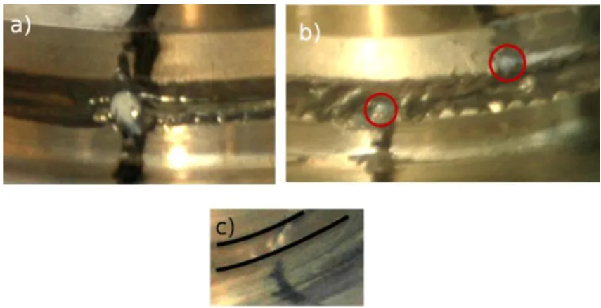
FIG. 6. Direct visualization of shear localization in highly concentrated MR suspensions upon application of a magnetic field strength, H0=18.5 kA/m. At subcritical shear rate, =0.01 s-1, the initially straight pigmented
column (a) breaks into two parts in the middle plane, the lower part being adhered to the lower plate and the upper part moving as a whole with the upper plate (b). This behavior could be interpreted in terms of shear localization at the middle plane. At supercritical shear rate, =0.5 s-1, the column is strained in an affine way (c), manifesting a homogeneous deformation of the suspension. The red circles in (b) surround the two parts of the broken pigmented column. The black curves in (c) are guidelines indicating the position of the upper and lower rheometer plates.
As observed in Figs. 6a and 6b, at low shear rate, =0.01 s-1, for which regular stick-slip oscillations were detected, the pigmented column was ruptured approximately at its
14 middle height, the lower half remaining attached to the immobile lower plate, while the upper
half moving jointly with the upper plate. Apparently, during the motion of the upper plate,
both parts of the column seemed to be always perpendicular to the rheometer plates. At higher
shear rate, =0.5 s-1, for which the stick-slip instability did not occur, the pigmented column experienced a uniform deformation, spanning the gap between both plates and elongating as it
was tilted by the shear (see Fig. 6c). This could be taken as a proof of the existence of a
homogeneous deformation profile, corresponding to a stable steady-state flow, at supercritical
shear rates. On the other hand, the rupture of the pigmented column at subcritical shear rates
could be interpreted in terms of suspension fracture in the middle plane, with shear
localization occurring within a narrow lubrication layer.
In order to explain the stress oscillations on the basis of the existence of a narrow
lubrication layer, we must assume that this layer periodically appeared and disappeared, the
following being a likely scenario. The slow stress growth during the stick process could be
attributed to a homogeneous elastic deformation of the suspension as a whole. At some
critical strain, the suspension structure broke in the middle plane and the resulting blocks
(each of the two halves of the suspension) turned back, sliding over each other, which
15
FIG. 7. Macroscopic description of the different stages of the stick-slip phenomenon. From top to bottom: homogeneous deformation of the suspension as a whole; fracture of the suspension structure in the middle plane at a critical strain, crit (onset of the slip with formation of a lubrication layer); backward rotation of the two
suspension blocks with a sliding friction between them; stick of two blocks at some minimum strain, min. In the
bottom sketch it is indicated that during the block rotation (slip process) the local strain decreases by .
Since we found experimentally that the stress did not release to zero but was lowered
by a maximum of thirty percent (see Fig. 4), it was likely that the two suspension blocks did
not recover initial zero strain but turned back to some small angle at which they stuck to each
other once again. Thus, the local strain of both suspension blocks oscillated between some
maximum value corresponding to the onset of the slip and some minimum value
corresponding to the onset of the stick. The spatial period, of these oscillations can be expressed in terms of the local strain of the suspension blocks; is related to the time period,
16 reasoning, we estimate the spatial period, to be of the order of 0.035 at H0=18.5 kA/m and
0.06 at H0=26.5 kA/m. These values correspond to the displacements of the upper rheometer
plate by a distance of a few particle diameters, 2a. So, is of the order of the ratio, 2a/h, of the particle diameter to the gap thickness, h; namely, 2.5 (2 ) / a h at H0=18.5 kA/m and
4(2 ) /a h
at H0=26.5 kA/m. The smallness of the strain suggests that the stick-slip
phenomenon occurs at the particle scale, i.e. when the two suspension blocks slide over each
other a distance of the order of magnitude of the particle diameter (cf. Fig.7). The field effect
on the spatial period and the time period of oscillations [Fig. 5a] could be explained by the
formation of thicker particle structures with a larger spatial period when the magnetic field is
increased. Such a behavior (the formation of thicker particle structures as the applied field is
increased) has recently been revealed by X-ray microtomography [Borbáth et al. (2012)].
In next section, we present a theoretical model based on the considered microscopic
mechanism of the stick-slip phenomenon, and we estimate the period and amplitude of the
stress oscillations.
IV. THEORY AND DISCUSSION
As already stated, the most likely mechanism that may cause the stick-slip
phenomenon in MR suspensions is the periodic rupture and reformation of the particle
aggregates. In a first approximation, the field-induced structure of a concentrated MR
suspension can be presented as a periodic array of column-like aggregates that are often
reported in literature [see, for instance, Borbáth et al. (2012)]. In more details, we may
consider a hexagonal array of multi-chain aggregates whose thickness (or, equivalently, the
17 we do not attempt to predict the aggregate thickness as function of the applied field. Instead,
we restrict our theoretical analysis to the case of an applied magnetic field, H0=18.5 kA/m,
keeping in mind that our model could be applied to any value of the applied field just by using
the correct spatial period. At a chosen magnetic field, H0=18.5 kA/m, the spatial period found
from the temporal period of stress oscillations is equal to 2.5(2 ) /a h and appears to be close to the period, 1.9(2 ) /a h of the hexagonal array of three-chain aggregates shown in Fig.1c. In what follows, we will estimate the principal parameters of the stick-slip motion
for this particular structure.
During the stick process, the multi-chains are supposed to be strained in an affine way
with the whole suspension, and the strain is supposed to grow linearly with time. The
multi-chains are tilted by the applied strain and the suspension stress rises monotonically with the
strain and, consequently, with the time. However, at some critical strain, the stress achieves its
maximum value and then decreases with the strain. As discussed in one of our previous work
[López-López et al. (2012)], at strains higher than the critical one the MR structure becomes
mechanically unstable and, thus, it is supposed to be ruptured at the maximum point of the
stress-strain relation. The critical strain was estimated to be crit 0.115, and the failure of the MR structure at crit 0.115 likely corresponds to the onset of the slip. According to our visualization experiments (see Fig. 6), the multi-chain aggregates are expected to be ruptured
in their middle point. Afterwards, during the slip process, the upper and lower halves of the
ruptured aggregates are supposed to turn back until they reach the opposite halves of the
neighboring aggregates, as schematically depicted in Fig. 1c. Once in front of each other, due
to the attractive magnetic forces, the aggregate halves are supposed to stick immediately to
each other; this gives rise to the onset of the stick process. Thus, during the stick-slip process,
18 1.9 (2 ) /a h
, such that the local strain (associated to the angle between the aggregates and the magnetic field) fluctuates between the maximum value crit 0.115 and the minimum value min crit (see Fig. 7).
The temporal variation of the local strain during the slip can be estimated by equating
the magnetic and hydrodynamic torques acting on the network of half-chains. Because of the
symmetry of the problem with respect to the middle plane, the motion of both the lower and
the upper networks is completely equivalent, so that we may consider only one of the
networks. We assume that the aggregates move only in the shear plane and, consequently,
their rotation axis is parallel to the direction of the vorticity. The magnetic torque per unit
volume of the network can be found, in the general case, as the derivative of the network free
energy (or, equivalently, of the thermodynamic function F ) with respect to the strain angle :
, m T F T H . (1)
The thermodynamic function F is defined through the free energy of the suspension per unit
volume, F0, and can be written in terms of the local strain angle as follows López-López et
al. (2012): 2 2 2 2 0 0 0 1 1 cos sin 2 2 F F H H . (2)
where µ0=4∙10-7 H/m is the magnetic permeability of vacuum, and are the
components of the magnetic permeability tensor of the suspension in the reference frame of
the aggregates and along their major and minor axes, respectively, H is the magnetic field
19 suspension magnetic permeability is field-independent; this assumption is verified by the
magnetization measurements [cf. Fig.2] for the experimental range of the magnetic fields
(0-26.5 kA/m). By substitution of Eq. (2) into Eq. (1), the following expression is obtained for
the magnetic torque:
2 2 2 2
0 0
1
sin cos cos sin
2 m T H H . (3)
The components, and of the magnetic permeability tensor, were calculated elsewhere [López-López et al. (2012)] for a multi-chain structure. This structure was designed in such a
way that it could expand without losing the mechanical equilibrium until a critical strain at
which it broke. In Eq. (3) the derivatives of the longitudinal and transverse magnetic
permeabilities of the suspension are calculated as
2
/ ( / ) /( / ) ( / ) (1 ), ,
k k k k
, where the magnitudes /
and / are given in our previous work [López-López et al. (2012)]. Note that the transverse permeability appears to be almost constant, such that / 0. Taking into account the relation between the strain and the strain angle, tan, the magnetic torque can be expressed in terms of the local strain:
2 2 2 0 2 0 1 1 2 m T H H . (4)According to [López-López et al. (2012)], / , therefore, the first term of Eq.(4) appears to be negligible with respect to the second one and can be omitted. Note that,
because of the demagnetizing field of the MR sample, the magnetic field intensity H inside
20 component, zz, of the magnetic permeability tensor of the suspension [López-López et al.
(2012: 2 0 0 2 1 zz H H H . (5)
The hydrodynamic torque acting on the network of half-chains can be estimated
assuming that the network rotates in the quiescent ambient liquid, in such a way that in the
reference frame of the aggregates the liquid filtrates through the interstices between them. It is
clear that in its rotation the network will partially drag the suspending liquid. Therefore, since
the hydrodynamic torque depends on the relative velocity of the network with respect to the
liquid, the assumption of the quiescent liquid is a rough approximation to the problem, which
will, nevertheless, allow us to estimate the order of magnitude of the slip time. The torque will
be calculated using some kind of slender body theory adapted to an array of parallel slender
aggregates. The normal component of the hydrodynamic force, f, acting per unit height of
the network can be related to the hydraulic permeability of the network via the Darcy
filtration law. In the Appendix, we demonstrate that f is expressed through the velocity,
vz, of the multi-chain at its longitudinal position z by the following formula:
0 0 2 2 , 2 a h v S S f z r K a K , (6)
where 0 is the viscosity of the suspending liquid of the MR suspension, S is the surface of the
rheometer plates, ra h, a 2 is the hydraulic radius of the three-chain aggregates, K is the dimensionless hydraulic permeability of the hexagonal array of cylindrical aggregates (given
in Appendix), and is the angular velocity of the half-chains. Now, the hydrodynamic torque per unit volume of network is calculated as the integral of the product (f z ) along the height
21 of the network, h/ 2, in a similar way as in the classical slender body theory [Batchelor
(1970, 1971)]: / 2 0 1h h T f zdz V
. (7)Replacing the force density f by Eq. (6), taking into account that at small
angles and noting that the ratio of the surface to the volume, S/V, is equal to the inverse of the height of the network, 2/h, Eq. (7) takes the following form:
2 0( / ) 24 h h a T K , (8)
where glob is the local shear rate associated to the structure rotation. Note that the eventual compression of the aggregates during their rotation, something which decreases their
height, h/2, is an effect of second order of smallness on and, therefore, is not taken into account in our work. In the inertialess limit, the sum of both the magnetic and the
hydrodynamic torques, Eqs. (4) and (8), must be equal to zero, which gives a first-order
differential equation with respect to the local strain . This equation admits an approximate solution if the magnetic torque is interpolated by the following linear function of the strain:
Tm c (1/ 2)0H2 , (9)
with c360 being a numerical constant. At small variations of the strain, crit, the strain is found to decrease quasi-linearly with the time according to the equation:
exp 1 crit crit t t , (10)
22 where crit 0.115 is the strain at the onset of the slip, and is the relaxation time given by:
2 0 2 0 ( / ) 12 h a c K H , (11)
with the internal magnetic field intensity H() corresponding to the critical strain, crit. This
time is the characteristic time of the structure rotation under the action of the magnetic torque.
As observed in Eq. (11), the relaxation time is proportional to the viscosity of the suspending
liquid and inversely proportional to the square of the magnetic field intensity H and to the
hydraulic permeability of the network. The slip time is simply calculated from Eq. (10) as the
time required to decrease the strain by the value 1.9 (2 ) / a h:
slip crit t . (12)
For the magnetic field, H0=18.5 kA/m, Eqs. (11) and (12) give, respectively, a
relaxation time 1.21s and a slip time tslip0.29s. The latter is of the same order of
magnitude than the experimental value (0.20±0.05 s, cf. Fig. 4b). The discrepancy is likely
related to the assumption of quiescent suspending liquid, an assumption that overestimates the
hydrodynamic dissipation and leads to a higher slip time than the one observed in the
experiments. The complete stick-slip cycle is constituted by a linear growth of the local strain
during the stick time and a quasi-linear decrease of the local strain during the slip time,
according to the following equation:
min , 0
1 ( ) / ,
glob stick crit stick stick
t t t t t t t T , (13)
where T=tstick+tslip is the total period of the stick-slip cycle. The time response of the
23 in the expression for the magnetostatic stress. This expression was obtained in our previous
work for highly concentrated MR suspensions [López-López et al. (2012)]:
2
2 2 2 0 2 2 0 2 2 0 2 1 1 1 (1 ) 2 1 1 2 1 H H H . (14)The theoretical time-dependencies of the local strain and the stress are plotted in Fig.8.
The linear growth/decrease of the local strain is well illustrated in this figure, in accordance
with Eq. (13), while the stress signal has a smoother shape. The latter is connected to the
rounded shape of the stress-vs.-strain curve near its summit, where the structure breaks –see
López-López et al. (2012). Because of this, when the critical strain is approached, the stress
increases with the strain slower than linearly and, since the strain increases linearly with time
during stick, the theoretical stress presents a less rapid increase. In fact, from the theoretical
point of view / 0 when crit. The theoretical stress signal (Fig. 8) qualitatively predicts the features of the experimental one (Fig. 4b). Both in theory and in experiments, we
observe a monotonic stress growth during stick and a monotonic decrease during slip; the
stress amplitude is an order of magnitude lower than the stress maximum; and the stick time is
an order of magnitude higher than the slip one. However, the stress growth section is
quasi-linear in the experimental case, whereas it presents a rounded-shape curvature in the
theoretical one. This discrepancy could be explained by the fact that the real stress versus
24
FIG. 8. Theoretical time dependencies of the local strain and of the suspension shear stress for a highly concentrated MR suspension upon application of a magnetic field of strength H0=18.5 kA/m, and at the global
shear rate glob=0.01 s-1.
In what concerns the field dependency of the amplitude of stress oscillations, our
model predicts an increasing trend in qualitative agreement with experiments (cf. Fig. 5a). In
more details, the stress amplitude is given by the difference between the maximum stress,
max ( crit)
, and the stress corresponding to the minimum strain min crit . In the limit 0.3crit, the stress amplitude can be expanded into power series on , as follows:
2 2 2
( ) ( ) (1/ 2)( / ) ( )
crit
crit crit
, taking into account that
( / ) 0
crit
. Thus, deriving two times the shear stress [Eq. (14)] with respect to the strain, it becomes clear that the stress amplitude, , scales as 0H2()2, and therefore increases progressively with the magnetic field, taking into account that is an increasing function of the field.
At this point is worth mentioning some related results of numerical simulations
performed by other authors. Klingenberg et al. (1991) reported quite irregular oscillations of
25 seldom and random events. Bonnecaze and Brady (1992) found quite irregular fluctuations of
the electrostatic stress of electrorheological fluids at very low shear rates (Mason number
Ma=10-4), which became more regular at higher shear rates (Ma=10-2). Nevertheless, in the
latter case, microscopic rearrangements of the particles inside the aggregates and between
them seem to play an important role and provoke a non-negligible noise in the stress signal.
Furthermore, the shape of the stress signal appears to be rather different from that observed in
our experiments, with the slip time being approximately equal to the stick time and the
amplitude of the stress oscillations comparable to the pick value of the stress. Such
discrepancy with experiments could come from the fact that only a small number of particles
was used in the simulations and, consequently, the influence of local stochastic events did not
vanish.
Another important feature observed in our experiments is the disappearance of the
stick-slip phenomenon at some critical shear rate – see Fig. 5b. At this moment, we do not
have a clear explanation for the absence of the stick-slip at higher shear rates. We suppose
that this could be connected to the kinetics of reformation of structures after their rupture at a
critical (yield) stress.
A further analysis of the suspension microstructure inherent to the stick-slip instability
requires knowledge of the interparticle gaps. Using our model of homogeneous elongation of
the aggregates upon shearing, we estimate that, at the maximum extension, the interparticle
gap is about 0.7% of the particle diameter, i.e. 33nm for the particles with 5µm of diameter.
Such a small gap is, at the most, of the same order of magnitude as the particle roughness.
Therefore, we expect that solid friction between particles plays an important role in the
reformation of aggregates during their backward motion. Once in contact, boundary
26 friction forces with features similar to those of solid friction [Persson (2000)]. In order to
check if the contacts between particles are governed by hydrodynamic lubrication (squeeze
repulsive forces) or boundary lubrication (friction forces), we calculated the ratio of squeeze
forces to normal interparticle forces:
2 0 0 2 3 /(2 ) s n m m F a v v F a f f , (15)
where v h t/ slip is the characteristic velocity of approach of particles belonging to opposite aggregates, 50nm is the particle roughness and fm is the characteristic magnetic
force (per unit particle cross-section, a2) between two particles separated by a distance . We calculated the force fm by integration of the Maxwell stress tensor over the outer face of the
surface of one of the particles using finite element method simulations [software FEMM,
Meeker (2009)]. We obtained that fm 3600H2, with H being the magnetic field inside the MR fluid [cf. Eq. (5)] at the critical strain, crit 0.115. For the experimental parameters corresponding to the stick-slip phenomenon shown in Fig. 4b, Eq. (15) gives FS /Fn 102,
which confirms the importance of friction forces for particles in contact. Thus, when two
halves of the broken aggregates come into contact, a tangential friction force likely appears in
the contact area, oriented in the direction of the applied shear. Estimations show that this force
is relatively strong and creates a supplementary torque, which very likely balances the
restoring magnetic torque and stops the backward rotation of the broken aggregates at the first
encounter with the neighboring ones. Of course, friction should also affect the conditions of
the structure failure [as pointed out by Tian et al (2010)] and could thus enhance the stress
level in the suspension. However, this matter is out of scope of the present paper and will be
27
V. CONCLUSIONS
We have shown that the rheograms (shear stress-vs.-shear rate curves) of concentrated
MR suspensions present a decreasing branch at low values of the shear rate. In this region of
negative differential viscosity the stable flow of the suspension is impossible, as proved by the
stress oscillations obtained for each imposed shear rate within this decreasing branch. The
obtained stress oscillations present well-defined amplitude and period, which appear to
increase with the applied field strength. These stress oscillations are reminiscent of the
stick-slip instabilities reported by other authors for different colloidal suspensions and, in fact, our
macroscopic visualizations have shown that the observed oscillations are correlated with the
appearance of a fracture layer at middle height of the sheared suspension. Consequently, we
have explained these oscillations by a mechanism of elongation of the field-induced particle
aggregates until their failure at a critical strain, followed by recombination among broken
parts of neighboring aggregates. Taking this as the starting point, we have developed a model
based on the balance of the torques acting on the field-induced particle structures. Our model
predicts a magnetic field dependence characterized by an increase of the amplitude of the
stress oscillations, explaining it in terms of enhanced magnetic interactions. Finally, we have
tried to estimate whether the flow of our suspension corresponds to lubricated contacts
between particles (squeeze repulsive regime) or to direct contacts with solid friction
(frictional regime). Calculations have shown that friction forces dominate over squeeze forces
for the characteristic parameters of our experiments. Nevertheless, the solid friction between
particles is expected to be a supplementary but not decisive mechanism of the stick-slip
phenomenon. We should maintain the rupture/reformation mechanism as the principle reason
28
ACKNOWLEDGEMENTS
We would like to thank Drs. Laurent Lobry and Andrey Zubarev for helpful
discussions. Financial support by projects Fis2009-07321 (Ministerio de Ciencia e
Innovación, Spain), P08-FQM-3993 and P09-FQM-4787 (Junta de Andalucía, Spain), and “Factories of the Future” (Grant No. 260073, DynExpert FP7) is gratefully acknowledged.
MTL-L and LR-A acknowledge financial support by the University of Granada (Spain) and
Secretaría de Estado de Educación, Formación Profesional y Universidades (MECD, Spain)
through its FPU program respectively.
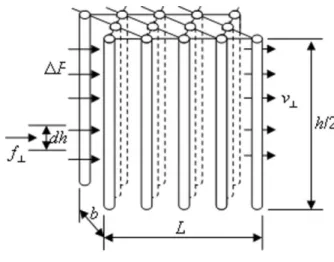
APPENDIX: HYDRAULIC RESISTANCE OF THE NETWORK OF MULTI-CHAIN AGGREGATES
Let us consider a laminar filtration flow of an interstitial liquid through a periodic
hexagonal array of triple-chain aggregates, as shown in Fig. A1. The flow is perpendicular to
the aggregates and the superficial velocity is equal to v. Our aim is to calculate the
hydrodynamic force, f, acting per unit height, dh, of this network.
29 The distance between chain the axes, given in Table II, is
2 /( 3 ) 1.9 (2 )
d a a . It is reasonable to approximate the elongated shape of the
chains by a straight cylinder with equivalent (or hydraulic) radius corresponding to the radius
of a cylindrical column having equal volume to that of the solid phase of the chain:
, 2
a h
r a . The unit hydrodynamic force, f, can be expressed through the pressure difference, P, of the liquid across the network:
f P b, (A.1)
where b is the network dimension perpendicular to the flow (network width). The pressure
difference is found from the Darcy filtration law with an appropriate hydraulic permeability,
K, of the network: 0 2 , a h L P v r K , (A.2)
where L is the network dimension along the flow (network length) and the permeability K is
normalized by the square of the column radius, ra h, 2, and given by the expression derived by
Bruschke and Advani (1993) using the lubrication approximation:
1 2 2 2 3 2 atan( (1 ) /(1 ) (1 ) 1 3 1 2 3 3 1 l l l K l l l l , (A.3)
with l2ra h, /d 2 3 / 0.742 being the ratio of the hydraulic diameter of the aggregates to the distance between them. By substitution of Eq. (A.2) into Eq. (A.1), and
taking into account that the product Lb is the network surface perpendicular to the aggregates,
30 Eq. (6). Of course, in our experiments with shear flow in plate-plate geometry, we do not
expect any pressure gradient along the circumferential direction of the flow. Filtration at
homogeneous superficial velocity is considered here only for the purpose of the estimation of
the network resistance coefficient. This coefficient (prefactor at 0v in the expression for
f) is then used for the calculation of the hydrodynamic torque of the rotating network, Eqs.
(7) and (8). The same artifice was used in the classical slender body theory for the calculation
of the resistance coefficients for the Stokes flow around a cylinder, which were subsequently
used for the calculation of the torque and the stresslet in shear flows [Batchelor (1970)].
References
Batchelor, G. K., “Slender-body theory for particles of arbitrary cross-section in Stokes flow,”
J. Fluid Mech. 44, 419–440 (1970).
Batchelor, G. K., “The stress generated in a non-dilute suspension of elongated particles by
pure straining motion,” J. Fluid Mech. 46, 813–829 (1971).
Bécu, L., S. Manneville, and A. Colin, “Yielding and flowing adhesive and non-adhesive
concentrated emulsions,” Phys. Rev. Lett. 96, 138302 (2006).
Bonn, D., P. Coussot, H.T. Huynh, F. Bertrand, and G. Debrégeas, “Rheology of softglassy
materials,” Europhys. Lett. 59, 786–792 (2002).
Bonnecaze, R. T., and J. F. Brady, “Dynamic simulation of an electrorheological fluid,” J.
Chem. Phys. 96, 2183-2202 (1992).
Borbáth T, S. Günther, D. Yu. Borin, Th. Gundermann,and S. Odenbach, “XmCT analysis of
magnetic field-induced phase transitions in magnetorheological elastomers”, Smart Mater.
31 Bruschke, M. V., and S. G. Advani, “Flow of generalized Newtonian fluids across a periodic
array of cylinder,” J. Rheol. 37, 479–498 (1993).
Coussot, P., J. S. Raynaud, F. Bertrand, P. Moucheront, J.P. Guilbaud, H.T. Huynh, S. Jarny,
and D. Lesueur, “Coexistence of liquid and solid phases in flowing soft-glassy materials,”
Phys. Rev. Lett. 88, 218301 (2002).
Coussot, P., L. Tocquer, C. Lanos, and G. Ovarlez, “Macroscopic vs. local rheology of yield
stress fluids,” J. Non-Newtonian Fluid Mech. 158, 85–90 (2009).
Da Cruz, F., F. Chevoir, D. Bonn, and P. Coussot, “Viscosity bifurcation in foams, emulsions
and granular systems,” Phys. Rev. E 66, 051305 (2002).
de Vicente J. and J. Ramírez, “Effect of Friction between Particles in the Dynamic Response
of Model Magnetic Structures,” J. Coll. Interface Sci. 316, 867-876 (2007)
Fall, A., F. Bertrand, G. Ovarlez, and D. Bonn, “Yield Stress and Shear Banding in Granular
Suspensions,” Phys. Rev. Lett. 103, 17830 (2009).
Huang, N., G. Ovarlez, F. Bertrand, S. Rodts, P. Coussot, and D. Bonn, “Flow of wet granular
materials,” Phys. Rev. Lett. 94, 028301 (2005).
Ianni, F., R. Di Leonardo, S. Gentilini, and G. Ruocco, “Shear-banding phenomena and
dynamical behavior in a Laponite suspension,” Phys. Rev. E 77, 031406 (2008).
Jarny, S., N. Roussel, S. Rodts, R. Le Roy, and P. Coussot, “Rheological behavior of cement
pastes from MRI velocimetry,” Concrete Cement Res. 35, 1873–1881 (2005).
Jiang J., Yu Tian, and Y. Meng, “Stick-slip motion of MR fluids during shearing,” in
Abstracts of the 13th International Conference on Electrorheological Fluids and Magnetorheological Suspensions, ed. I. Unal (2012), pp. 138-139.
32 Jiang J., Yu Tian, and Y. Meng, “Structure Parameter of Electrorheological Fluids in Shear
Flow,” Langmuir 27, 5814–5823 (2011)
Jiles, D., Introduction to Magnetism and Magnetic Materials (Chapman and Hill, London,
1991).
Klingenberg D. J., and C. F. Zukoski, “Studies on the steady-shear behavior of
electrorheological suspensions,” Langmuir 6, 15–24 (1990).
Klingenberg, D. J., F. Vanswol and C. F. Zukoski, “The small shear rate response of
electrorheological suspensions .1. Simulation in the point-dipole limit,” J. Chem. Phys. 94,
6160-6169 (1991).
Kuzhir P., M. T. López-López and G. Bossis, “Magnetorheology of fiber suspensions. II. Theory”, J. Rheol. 53, 127-151 (2009).
Kuzhir, P., M. T. López-López, G. Vertelov, C. Pradille, and G. Bossis, “Shear and squeeze
rheometry of suspensions of magnetic polymerized chains,” Rheol. Acta 47, 179-187
(2008).
López-López, M.T., P. Kuzhir, J. Caballero-Hernández, L. Rodríguez-Arco, J. D. G. Durán, and G. Bossis, “Yield stress in magnetorheological suspensions near the limit of
maximum-packing fraction,” J. Rheol. 56, 1209-1224 (2012).
Meeker D. C., Finite Element Method Magnetics, Version 4.2 (15 July 2009 Mathematica
Build), http://www.femm.info
Ovarlez, G., F. Bertrand, and S. Rodts, “Local determination of the constitutive law of a dense
33 Ovarlez, G., S. Rodts, X. Chateau, and P. Coussot, “Phenomenology and physical origin of
shear localization and shear banding in complex fluids,” Rheol. Acta 48, 831-844 (2009).
Persello, J., A. Magnin, J. Chang, J. M. Piau, B. Cabane, “Flow of colloidal aqueous silica
dispersions,” J. Rheol. 38, 1845–1870 (1994).
Persson, B. N. J., Sliding Friction. Physical principles and applications (Springer-Verlag,
Berlin 2000).
Picard, G., A. Ajdari, L. Bocquet, and F. Lequeux, “Simple model for heterogeneous flows of
yield stress fluids,” Phys. Rev. E 66, 051501 (2002).
Pignon, F., A. Magnin, and J. M. Piau, “Thixotropic colloidal suspensions and flow curves
with minimum: Identification of flow regimes and rheometric consequences,” J. Rheol. 40,
573–587 (1996).
Quemada, D., “Unstable flows of concentrated suspensions,” Lect. Notes Phys. 164, 210-247
(1982).
Ragouilliaux, A., G. Ovarlez, N. Shahidzadeh-Bonn, B. Herzhaft, T. Palermo, and P. Coussot, “Transition from a simple yield stress fluid to a thixotropic material,” Phys. Rev. E 76,
051408 (2007).
Rodts, S., J. C. Baudez, and P. Coussot, “From discrete to continuum flow in foams,”
Europhys. Lett. 69, 636–642 (2005).
Tian Yu, J. Jiang, Y. Meng, and Sh. Wen, “A shear thickening phenomenon in magnetic field
34 Tian Yu, M. Zhang, J. Jiang, N. Pesika, H. Zeng, J. Israelachvili, Y. Meng, and Sh. Wen, “Reversible shear thickening at low shear rates of electrorheological fluids under electric
fields,” Phys. Rev. E 83, 011401 (2011)
Tian Yu, M. Zhang, X. Zhu, Y. Meng, and Sh. Wen, «Ultrahigh yield stress in a general
electrorheological fluid under compression,” Smart Mater. Struct. 19, 035009(2010-b)
Varadan, P., and M. J. Solomon, “Direct visualization of flow-induced microstructure in
dense colloidal gels by confocal laser scanning microscopy,” J. Rheol. 47, 943–968 (2003).
Woestman, J. T., “Stick-slip response in electrorheological fluids,” Phys. Rev. E 47, 2942–