Biomimetic Design of an Under-Actuated Leg Exoskeleton For Load-Carrying Augmentation
by
Conor James Walsh
B.A.I, B.A. Mechanical and Manufacturing Engineering (2003)
Trinity College Dublin
Submitted to the Department of Mechanical Engineering in Partial Fulfillment of the requirements for the Degree of
Master of Science in Mechanical Engineering at the
Massachusetts Institute of Technology February 2006
C 2006 Massachusetts Institute of Technology All rights reserved
Signature of Author:... ... . .. Z. .... ... *III ... **...
Department of Mechanical Engineering January 19th, 2006
Certified by: ...
Hugh Herr /Associate Professor of Media Arts and Sciences Thesis Supervisor Certified by:... ... . /1 A
A
A~+~Ab~7. rL U...YL a~ ... Derek Rowell Professor of Mechanical Engineering Thesis SupervisorLallit Anand Professor of Mechanical Engineering Chairman, Department Committee on Graduate Students
MA SSACHUSETS INSTITUTE
Biomimetic Design of an Under-Actuated Leg Exoskeleton For Load-Carrying Augmentation
by
CONOR JAMES WALSH
Submitted to the Department of Mechanical Engineering on January 19th, 2006 in partial fulfillment of the requirements for the
Degree of Master of Science in Mechanical Engineering
Abstract
Metabolic studies have shown that there is a metabolic cost associated with carrying a load (Griffin et al, 2003). Further studies have shown that by applying forward propulsive forces a person can walk with a reduced metabolic rate (Farley & McMahon,
1992 and Gottschall & Kram, 2003). Previous work on exoskeleton design has not
considered the passive dynamics of walking and has focused on fully actuated systems that are inefficient and heavy. In this thesis, an under-actuated exoskeleton is presented that runs parallel to the human leg. The exoskeleton component design is based on the kinematics and kinetics of human walking. The joint components of the exoskeleton in the sagittal plane consist of a force-controllable actuator at the hip, a variable-damper mechanism at the knee and a passive spring at the ankle. A state-machine control strategy is written based on joint angle and ground-exoskeleton force sensing. Positive, non-conservative power is added at the hip during the walking cycle to help propel the mass of the human and payload forward. At the knee, the damper mechanism is turned on at heel strike as the exoskeleton leg is loaded and turned off during terminal stance to allow knee flexion. The spring at the ankle engages in controlled dorsiflexion to store energy that is later released to assist in powered plantarflexion.
Kinetic and metabolic data are recorded from human subjects wearing the exoskeleton with a 751b payload. These data are compared to data recorded from subjects walking without the exoskeleton. It is demonstrated that the exoskeleton does transfer loads to the ground with a 90% and higher load transfer depending on the phase of gait. Further, exoskeleton wearers report that the exoskeleton greatly reduces the stress on the shoulders and back. However, although a significant fraction of the payload is transferred through the exoskeleton structure, the exoskeleton is found to increase metabolic economy by 74%. By comparing distinct exoskeleton configurations, the relative effect of each exoskeleton component is determined. Metabolic data show that the variable-damper knee and ankle spring mechanisms increase metabolism by only
32%, whereas a non-actuated exoskeleton (no motor, variable-damper, or spring)
increases walking metabolism by 62%. These results highlight the benefit of ankle elastic energy storage and knee variable-damping in exoskeleton design, and further the need for a lighter, more efficient hip actuator.
Thesis Supervisor: Hugh Herr
Acknowledgments
My time spent working on this thesis has been both interesting and enjoyable. This is due
to the fact that I have gained tremendously as a result of having worked alongside many interesting and dedicated colleagues. In particular, I would like to thank Professor Herr for having given me the opportunity to work in the Biomechatronics Group and for his constant assistance and motivation. I would also like to thank 'Dr.' Daniel Paluska and Dr. Ken Pasch for their advice and mentoring during the period which I spent working on my thesis. I have gained a lot of knowledge from the both of them. Thanks also to
Professor Rowell for his advice and guidance.
May I also offer thanks to those in the Biomechatronics Group with whom I have worked for making it such an exciting working environment. Goutham Reddy for all his electronics advice and techno beats. Sam Au for all his control help and runs along the banks of the river Charles. Bruce Deffenbaugh for his constant willingness to help on any topic and for all the late night cups of tea. Peter Dilworth for his design advice and life-saving chokes. William 'Guillermo' Grand for being the most dedicated person I have ever met and the late nights in Johnson track during the summer. Waleed Farahat for his help with anything related to Matlab and for always looking at the theoretical side of things. Russ Tedrake for onsite PC 104 technical support. Ernesto Martinez for his sensor advice and for the headphones. Andrea Chew for the GUI help and for her phone charger. Thanks also to all other friends and staff at MIT who have made life so enjoyable and fulfilling for me.
Thanks also to Mum and Dad and to my brothers Damien and Niall for always keeping my ego in check. Thanks also to the lads at chez Jay and chez Elm, life is all the better when you're living with good friends. And finally, my thanks to that special lady - you know who you are!
This research was done under Defense Advanced Research Projects Agency (DARPA) contract #NBCHC040122, 'Leg Orthoses for Locomotory Endurance Amplification'.
Table of Contents
A bstract ... 1
A cknow ledgm ents... in Table of Contents... iv
List of Figures ... v
List of Tables ... vii
1 Introduction... 1
1.1 Metabolic effect of forces applied to the human during walking ... 2
1.2 Biom echanics of Load Carrying ... 4
1.3 Exoskeleton Concept and Background ... 5
1.4 M otivation for a Sem i-A ctive Approach ... 7
1.5 Contributions... 8
1.6 Hypotheses... 9
1.7 Thesis Outline ... 9
2 Biom echanical Gait Analysis... 10
2.1 Hum an Gait... 10
2.2 M uscle A ctivity in Gait... 12
2.3 Human Walking Biomechanics in the sagittal plane ... 14
3 Electro-M echanical D esign of Exoskeleton... 23
3.1 Functional Requirem ents ... 23
3.2 Exoskeleton Structure ... 24
3.3 Exoskeleton D egrees of Freedom ... 24
3.4 Exoskeleton interface to the hum an... 26
3.5 Final A ssem bly ... 28
3.6 A ctuation... 29
3.7 Exoskeleton Prototype Im provem ents ... 45
4 Controller Im plem entation... 49
4.1 Electronics Test Bed ... 49
4.2 Sensing ... 52
4.3 Control Strategies... 55
5 Experim ental M ethods... 63
5.1 Experim ental Subjects ... 63
5.2 D ata Collection ... 63
5.3 Experim ental Protocol ... 65
5.4 D ata A nalysis ... 66
6 Results and D iscussion ... 68
6.1 K inem atic and K inetic D ata... 68
6.2 M etabolic M easurem ents ... 71
7 Conclusion ... 77
8 Future W ork ... 78
References ... 79
Appendix A : Carbon Fiber H arness Construction... 82
List of Figures
Figure 1.1 Concept sketch of the main components of the exoskeleton... 2
Figure 1.2 Summary of results from metabolic studies ... 3
Figure 1.3 Results showing an optimal forward assistive force of 10% when walking .... 3
Figure 1.4 Increasing metabolic rate with increasing payload and speed... 4
Figure 1.5 Load-Carrying Exoskeletons ... 6
Figure 1.6 A ssistive Exoskeletons ... 7
Figure 1.7 Passive Dynam ic W alkers ... 8
Figure 2.1 Reference planes of body in standard anatomic position ... 10
Figure 2.2 Sign convention used for joint angles ... 11
Figure 2.3 The eight main phases of the walking cycle from heel strike to heel strike... 11
Figure 2.4 A sim ple m odel of walking ... 12
Figure 2.5 Significant regions of positive and negative work in walking ... 13
Figure 2.6 Gait data showing the trajectory of the hip, knee and ankle joint ... 14
Figure 2.7 Hip angle and torque profiles scaled for a 135kg person ... 16
Figure 2.8 Hip joint power profile scaled for a 13 5kg person... 16
Figure 2.9 The hip angle plotted versus hip torque for a walking speed of 0.8m/s... 17
Figure 2.10 Knee angle and torque profiles scaled for a 60kg person... 18
Figure 2.11 Knee joint power profile scaled for a 60kg person... 19
Figure 2.12 A plot of knee angle versus knee torque for the walking cycle... 19
Figure 2.13 The ankle angle and torque profile scaled for a 60kg person are shown ... 20
Figure 2.14 Ankle joint power profile scaled for a 60kg person ... 21
Figure 2.15 Plot of ankle angle versus ankle torque for the walking cycle ... 22
Figure 3.1 The main components of the exoskeleton ... 23
Figure 3.2 Finite element results from testing the exoskeleton thigh and shank... 24
Figure 3.3 Schematic of exoskeleton structure and degrees of freedom of exoskeleton. 25 Figure 3.4 Foam mockup of the exoskeleton harness being tested... 26
Figure 3.5 Finite element analysis of the carbon fiber harness... 27
Figure 3.6 Exoskeleton components prior to assembly ... 28
Figure 3.7 Rotary series elastic actuator schematic... 29
Figure 3.8 CAD model of the linear series elastic actuator ... 30
Figure 3.9 Testing the hip actuators for two different boundary conditions ... 31
Figure 3.10 Actuator model showing controller and lumped parameter model ... 32
Figure 3.11 Lumped parameter model for the actuator (Robinson, 2000). ... 32
Figure 3.12 Model of the actuator showing the load mass on the end (Robinson 2000). 33 Figure 3.13 Output response (red) to an input chirp signal (blue)... 34
Figure 3.14 Open loop response for the fixed end condition... 34
Figure 3.15 Open loop Bode plots for SEA for two end conditions... 35
Figure 3.16 Closed loop Bode plot for the actuator for the fixed end condition... 37
Figure 3.17 Closed loop testing of actuator for fixed end condition ... 37
Figure 3.18 Large force bandwidth of actuator ... 38
Figure 3.19 Closed loop testing of actuator with an equivalent load mass of 350kg ... 39
Figure 3.20 Closed loop testing of actuator for load mass end condition... 39
Figure 3.21 Closed loop position control testing ... 40
Figure 3.24 Uni-directional ankle spring ... 43
Figure 3.25 Exoskeleton foot and the shoe worn by the wearer... 44
Figure 3.26 Section view of the adduction spring assembly at the hip joint. ... 45
Figure 3.27 Revised foot and ankle design... 46
Figure 3.28 Exoskeleton spine to attach the backpack to the harness. ... 47
Figure 4.1 Schematic of the electronic components ... 49
Figure 4.2 Digital amplifiers from copley ... 51
Figure 4.3 Signal conditioning board... 51
Figure 4.4 Sensors on the exoskeleton leg... 52
Figure 4.5 Timing belt and pulley on inside of harness... 53
Figure 4.6 Schematic of exoskeleton shank and foot ... 54
Figure 4.7 Thigh cuff sensor... 55
Figure 4.8 Summary of the actuation control of the exoskeleton leg ... 55
Figure 4.9 State-machine diagram for the knee controller ... 57
Figure 4.10 Sensor data from the exoskeleton leg for a single gait cycle ... 58
Figure 4.11 The state machine for the exoskeleton knee in operation... 59
Figure 4.12 State machine diagram for the hip controller ... 60
Figure 4.13 Sensor data from the exoskeleton leg for a single gait cycle ... 61
Figure 4.14 The state machine for the exoskeleton hip in operation... 61
Figure 4.15 GUI used to vary the parameters for gait cycle state-machine tuning. ... 62
Figure 5.1 Caddy velocity calibration... 64
Figure 6.1 Hip and knee angle data of the exoskeleton as a function of gait cycle... 69
Figure 6.2 Load in the exoskeleton leg shank as a function of gait cycle ... 69
Figure 6.3 Moment in the exoskeleton shank as a function of gait cycle... 70
List of Tables
Table 2.1 Specifications for the hip joint of the exoskeleton ... 17
Table 2.2 Specifications for the knee joint of the exoskeleton... 20
Table 2.3 Specifications for the ankle joint of the exoskeleton... 22
Table 3.1 Exoskeleton degrees of freedom... 25
Table 3.2 Maximum torque and angular velocity calculations for hip joint... 30
Table 3.3 Experimentally obtained system parameters ... 35
Table 3.4 Physical values of the elements in the lumped parameter model ... 35
Table 4.1 Description of states and their respective triggers for the knee ... 57
Table 4.2 Description of states for hip controller. ... 59
Table 5.1 Experim ental participant data. ... 63
Table 6.1 Summary of metabolic data from experiments... 71
Table 6.2 Metabolic cost for the various experiments performed ... 72
Table 6.3 Comparison of walking with 751bs with and without the exoskeleton... 73
Table 6.4 The effect of increased mass for actuation at the ankle and knee... 74
Table 6.5 The metabolic cost of wearing the exoskeleton with no load... 75
1
Introduction
When compared to wheeled vehicles, exoskeleton-based assistive devices have several advantages, such as allowing the user to traverse irregular terrain. Individuals employed in specific recreational, occupational and military pursuits often carry heavy loads using a variety of backpack systems. Recreational hikers and backpackers commonly carry subsistence and comfort items in backpacks (Fletcher, 1994). Fire fighters and other emergency personnel carry oxygen tanks for breathing and other equipment using backpack systems (Louhevaara et al., 1985). Still further, foot soldiers often carry extremely heavy backpack loads and walk long distances across rough terrain (Fletcher,
1994).
A leg exoskeleton could benefit people who engage in load carrying by increasing load
bearing capacity, speed and endurance, lessening the likelihood of injury, improving efficiency and reducing the perceived level of difficulty. Exoskeletons have been developed that amplify the strength of the wearer, apply assistive torques to the wearer's joints and support a payload for the wearer. Several exoskeleton design approaches have employed hydraulic actuators to power hip, knee and ankle joints in the sagittal plane. Such an exoskeleton design demands a great deal of power, requiring a heavy power supply to achieve system autonomy. For example, the Bleex developed at the University of California, Berkeley (Chu et al., 2005) consumes approximately 2.27kW of hydraulic power, 220 Watts of electrical power, and has a total system weight of 100 lbs. This approach leads to a noisy device that has a very low payload to system weight ratio. Further, this type of exoskeleton is heavy and, if failure were to occur, could cause
significant harm to the wearer.
This thesis examines biomechanical data from human walking and outlines the design of an alternative, more efficient exoskeleton that uses both passive and active elements. The exoskeleton actuation in the sagittal plane consists of a non-conservative actuator at the hip, a variable-damper mechanism at the knee, and springs at the ankle. The actuator at
the hip allows power to be added at desired instances throughout the gait cycle to propel the wearer forward and to reduce the effects of exoskeleton mass.
Backpack
Hip Actuator Pelvic
Harness
Knee Brake Thigh Cuff
Foot
Ankle Spring Attachment
Figure 1.1 Concept sketch of the main components of the exoskeleton.
A state-machine control strategy is written based on joint angle sensing as well as
ground-exoskeleton interaction sensing. When the human foot is on the ground, the exoskeleton transfers the forces from the loaded backpack to the ground. Using the force-controllable actuator at the hip, positive power is added at the hip during the stance phase to propel the mass of the human and payload forward, and to cancel the mass of the human and exoskeleton leg during the swing phase. The variable-damper mechanism at the knee is turned on during early stance to provide support for the load and is then switched off during terminal stance and swing to minimize resistance at the knee joint. The passive spring at the ankle engages in controlled dorsiflexion to store energy that is later released to assist in powered plantarflexion.
1.1
Metabolic effect of forces applied to the human during walking
Walking metabolism is set by muscles that act to perform work on the center of mass, swing the legs relative to the center of mass, and support the body weight. A number of researchers have performed metabolic experiments where external loads were applied to the body in vertical and horizontal directions. The results of these experiments are summarized below in Figure 1.2.
unweighting
50% antigravil 25% reduction
Farley & McMahon,
drag force
10% BW impeding 150% Increase 4
Gottscholl & Kram, 2003
force ,
ty monitor
1992
forward assist force 10% BW assist
47% reduction
Gottschall & Kram, 2003
additional mass
10% BM addition 15% increase
Griffin et al, 2003
treadmill
Figure 1.2 Summary of results from metabolic studies while exerting external forces on the human (Figure courtesy of Daniel Paluska).
One set of experiments recorded metabolic data while various levels of assistive and impeding external horizontal forces were applied to the waist of a subject walking on a treadmill (Gottschall and Kram, 2003). A 47% reduction in metabolic rate was found when an aiding horizontal force equal in magnitude to 10% body weight was applied to a person. Further, the study showed that the 10% value was optimal and that a larger assisting force increased metabolic demands.
U ~2
N
I
120 110 100 90 80 70 60 30 40Figure 1.3 Results showing an optimal
2003).
*
*
*
15 A 10A 5 A 0
Applied Horizontal Force (% Body Weight)
forward assistive force of 10% when walking (Gottschall and Kram,
Other metabolic experiments have been performed to examine the effect of load carrying on metabolic rate. In these investigations, it was found that net metabolic rate increased as subjects carried heavier loads and the percent increase due to loading was found to be similar at all speeds. Further, Pandolf et al. (1978) found that when a human carried a load equivalent to 40% of body weight, the rate of energy consumption during walking increased by approximately 40%. Griffen et al. (2003) found a similar result. When subjects carried loads equal to 30% of their body mass, the net metabolic rate increased
47 +- 17% above their unloaded rate.
6W00 500 4W0 o S2W0 10061.M, .1.0 Mb 0 . . I . . . 1 0.0 0.5 1.0 1-5 2.0 Speed (m s-)
Figure 1.4 Increasing metabolic rate with increasing payload and speed (Griffen et al., 2003).
Researchers have also performed experiments to examine the effect of gravity on the metabolic rate of walking (Farley and McMahon, 1992). In this investigation, a series of steel springs were used to apply a nearly constant upward force to the body through a bicycle saddle. This reduced the force that the muscles had to generate to support the weight of the body. These researchers discovered that by reducing gravity by 50%, the metabolic rate reduced by 25%.
1.2
Biomechanics of Load Carrying
There has been much research on the biomechanics of human gait published in the literature. However, there has only been a very small proportion of research published on load carrying biomechanics. Much of the work that has been done in the area has been carried out by the Military due to its relevance to soldiers carrying heavy backpack loads
for long periods of time. Many associated medical injuries have been reported involving tissue damage under straps, back problems and lower limb injuries (Jones, 1983; Knapik
et al., 1996). Another common injury is metatarsalgia which results from the foot
rotating anteroposteriorly around the distal ends of the metatarsal bones for prolonged periods of time. Other common injuries include stress fractures in the lower limb, knee pain and lower-back injuries. In one study 50% of the soldiers who were unable to complete a strenuous 20-km walk reported problems associated with the back (Knapik et
al., 1992). Dalen et al. (1978) reported a 15% incidence (17 cases out of 114) of knee
pain during load-carriage from subjects walking for long periods of time. These studies all showed that backpack load carrying caused significant stress on the shoulders, back and leg joints.
During load-carrying, propulsive, braking and vertical ground reaction forces increase in proportion to increasing load carried (Harman et al., 2000). In a study they found that for a body plus mass increase by 40%, ankle peak plantarflexion torque increased by 38%, knee peak extension torque increased by 98% and hip peak extension torque increased by 47%. The forward inclination of the trunk also increased significantly with load, helping to keep the body plus pack center of mass over the feet. Other adaptations to load included greater knee flexion after impact (which aids in shock absorption), reduced pelvic rotation and increased foot rotation in the sagittal plane. These results all indicate that it is likely that a load-carrying exoskeleton could reduce the injuries associated with the back and lower limbs. Further, such an exoskeleton also has the potential to reduce walking metabolism compared to unassisted load carrying.
1.3 Exoskeleton Concept and Background
Exoskeletons have been developed that amplify the strength of the wearer, apply assistive torques to the wearer's joints and support a payload being carried by the wearer. General Electric developed and tested a prototype man-amplifier, a master-slave system called the Hardiman (General Electric, 1968). It consisted of a set of overlapping exoskeletons worn by the human operator and the outer exoskeleton followed the motions of the
operator. Difficulties in human sensing, stability of the servomechanisms, safety, power requirements and system complexity kept it from walking.
The Berkeley Lower Extremity Exoskeleton attached to the human foot and back. The hip, knee and ankle joints were powered in the sagittal plane with linear hydraulic actuators (Chu et al., 2005). The system was powered with an internal combustion engine that was also supported by the exoskeleton. Sarcos Inc. developed a similar exoskeleton with rotary hydraulics at the joints (Huang, 2004). Both systems sensed the intent of the wearer and the robotic legs tracked the human legs so the wearer did not 'feel' the exoskeleton. Other researchers are also developing a prototype of an exoskeleton to support a payload (Liu et al., 2004).
payload
-exoskeleton
exoskeleton
Figure 1.5 Load-Carrying Exoskeletons. In a), the Berkeley Lower Extremity Exoskeleton is shown with an IC engine attached on the back powering linear hydraulic actuators (Kazerooni et al., 2005). In b), the Sarcos, Inc. exoskeleton is shown with rotary hydraulic actuators and backpack (Huang, 2004), In c), a concept sketch of another exoskeleton in development is shown (Liu et al., 2004).
Vukobratovid et al. (1990) developed exoskeletons to aid walking for paraplegics. They assisted patients to walk by commanding the exoskeleton to track pre-defined trajectories. They had limited success in assisting subjects to walk, partly due to the fact that the devices were greatly limited by material, actuation and battery technology at the time. Researchers at the University of Tsukuba in Japan developed an exoskeleton power assist system to aid people with a gait disorder to walk (Sankai, 2004). They measured the joint angles, ground contact force and myoelectrical signals of the muscles and used these
signals to control the actuation applied to the wearer. The RoboWalker was developed to augment or replace muscular functions of the lower extremities (Pratt et al., 2004). This was done by powering the human hip and knee joints using series elastic actuators.
Figure 1.6 Assistive Exoskeletons. In a), a subject is shown with leg weaknesses stair climbing using an exoskeleton (Vukobratovic et al., 1990). In b), the exoskeleton from the University of Tsukuba is shown.
DC motors were used to power the hip and knee joint of the wearer (Sankai, 2004), In c), the RoboWalker
from Yobotics Inc. is shown. It used series elastic actuators to power the joints (Pratt et al, 2004)
1.4
Motivation for a Semi-Active Approach
Evidence from biology (Farley and Ferries, 1998) and passive walkers (McGeer, 1990) suggest that legged locomotion can be very energy efficient. The exchange between potential and kinetic energy suggests that walking may be approximated as a passive mechanical process. Passive walkers reinforce this fact. In such a device, a human-like pair of legs settles into a natural gait pattern generated by the interaction of gravity and inertia. Although a passive walker requires a modest incline to power its movements, researchers have enabled these robots to walk on level ground by adding just a small amount of energy at the hip or ankle joint (Wisse, 2004). Figure 1.7 shows some examples of actuated passive walkers. MIKE was a 2D pneumatically activated biped with knees, weighing only 6 kg. The actuation is realized with McKibben muscles at the hip joints. Denise is from the University of Delft and stands 1.5 m tall, weighs 8 kg, and walks with a velocity of 0.4 m/s. The hip joint was actuated and consisted of a bisecting mechanism which linked the two legs to each other. The ankles and knees were completely passive, except that the knee was provided with a controllable latch. The
Cornell biped was actuated at the ankle where it pushed off to restore energy lost, mostly due to heel strike collisions (Collins et al., 2005). The hip joint was fully passive and a latch at each knee passively locked the shank throughout stance.
Figure 1.7 Passive Dynamic Walkers. In a), a 2D pneumatically activated biped with knees, MIKE, is shown (Wisse, 2004). In b), Denis, a powered passive walker from Delft is shown. The robot is only actuated at the hip and can walk with a human like gait (Wisse, 2004). Lastly, in c), the Cornell biped is shown. It is actuated at the ankle only (Collins et al., 2005).
Recent evidence suggests that elastic energy storage is also critical for efficient bipedal ambulation. Palmer (2002) characterized the human ankle during the stance phase of walking in terms of simple mechanical spring elements. He showed that the sagittal plane dynamics of a normal ankle can be reproduced at least at slow to moderate walking speeds. Further, researchers have studied the placement of appropriate springs in parallel with the human (van den Bogert, 2004). It was shown in numerical simulation that an exoskeleton using passive elastic devices substantially reduced the muscle force and metabolic energy in walking.
1.5
Contributions
This thesis presents an alternative architecture to a fully actuated exoskeleton. Specifically, human walking data was analyzed and design specifications for actuation at the hip, knee and ankle joints were extracted. A controller was written that controls actuation at the hip and knee that allows the exoskeleton to support a payload and apply assistive torques to the wearer. The hypotheses guiding this research effort follow.
1.6 Hypotheses
The following are the specific hypotheses of this research effort:
1. An under-actuated leg exoskeleton consisting of a force-controllable actuator at
the hip, a variable-damper mechanism at the knee and a spring at the ankle will improve metabolic walking economy for carrying a 751b load compared with unassisted loaded walking.
2. The same exoskeleton will improve metabolic walking economy for carrying a
751b load compared with a minimal mass non-actuated exoskeleton (no motor, no
variable-damper or spring).
3. An under-actuated exoskeleton will transfer its own weight and that of a payload
to the ground during walking.
1.7 Thesis Outline
Chapter 2 provides background on some of the terms associated with human walking. It also examines human walking data at the hip, knee and ankle joint in the sagittal plane and provides design specifications for the exoskeleton. Chapter 3 describes the mechanical design of the exoskeleton and the characterization of the components used for actuation whilst Chapter 4 outlines the implementation of the electronics test-bed for sensing and control as well as describes the state-machine controller used to control the hip and knee. Chapter 5 details the experimental methods and metrics for quantifying the metabolic cost and Chapter 6 presents and discusses the results. Chapter 7 summarizes the conclusions of this work and Chapter 8 provides recommendations for future work.
2 Biomechanical Gait Analysis
This chapter provides background on describing human walking biomechanics and introduces the relevant terminology used in examining it. The energetics of walking is described and the significant regions of positive and negative power of the three main leg joints during a single walking cycle are highlighted. From this description, specifications
for joint actuation in the sagittal plane are extracted.
2.1
Human Gait
Walking uses a repetitious sequence of limb motion to move forward while simultaneously maintaining stance stability. The beginning of the gait cycle is represented as initial contact of one foot with the gait surface, usually termed heel strike (Perry, 1992). Walking is three dimensional but this thesis focuses only on the sagittal plane as the largest motions, torques and powers are in this plane.
"CMTAL PLAM
A
Figure 2.1 Reference planes of body in standard anatomic position (Inman et al., 1981).
The sign convention that is used is that each joint angle is measured as the positive counterclockwise displacement of the distal link from the proximal link (zero in standing position) with the person orientated as shown in Figure 2.2. In the position shown, the
hip angle is positive whereas both the knee and ankle angles are negative. Torque is measured as positive acting counterclockwise on the distal link.
+8 hip
N -e knee
-0 Ankle
Figure 2.2 Sign convention used for joint angles. Each joint angle is measured as the positive counterclockwise displacement from the distal link to the proximal link (Chu et aL, 2005).
Very simply, walking can be thought of as two phases, a stance phase and a swing phase. During the stance phase the muscles at the hip, knee and ankle generally act to decelerate and stabilize the body. At the end of the stance phase the ankle is in powered plantarflexion where it provides the energy to power the body forward. At the start of the swing phase, the hip gives a burst of energy to raise the leg and swing it forward. Figure
2.3 outlines the eight main phases of the walking cycle.
Initial ContacI Loading Rvmposc Mid-Stance Termmal Stance Pre-Swing Initial Suing Mid-Swing Temninal Suing
The kinetic and gravitational potential energy of the center of mass of the human are approximately 180 degrees out of phase in walking. At mid-stance in walking, the gravitational potential energy is at its maximum and the kinetic energy is at its minimum. Because these energies are approximately 180 degrees out of phase with each other and their fluctuations are similar in magnitude, substantial pendulum-like energy exchange occurs. In human walking, as much as 60-70% of the mechanical energy required to lift and accelerate the center of mass is conserved by this energy transfer mechanism (Farley and Ferris, 1998). Mechanical energy savings are maximized at moderate walking speeds, and fall toward zero at very low and very high walking speeds. This energy transfer mechanism in walking is often referred to as the "inverted pendulum mechanism".
Walk (125 m/s) 40-20-- Gravitational potential energy 1Ag 0 0 0.2 0.4 0.6 0.8 Tne (s)
Figure 2.4 A simple model of walking. In a), an illustration of the inverted pendulum type motion of the human during walking is shown. In b), the potential and kinetic energy fluctuations during walking are shown (Farley and Ferris, 1998).
2.2
Muscle Activity in Gait
Many muscles responsible for walking contract isometrically to allow for maintenance of upright posture against gravity. Brief bursts of more energy expensive contraction of muscle are added when needed to provide power for forward motion (Inman et al., 1981). Positive work is performed when a muscle is concentrically contracting whilst negative work is said to be performed when a muscle is eccentrically contracting. Much muscle activity in walking is isometric or eccentric. Negative work allows the limbs to absorb energy while resisting the pull of gravity, yet remain metabolically efficient. Positive work of muscles during walking allows acceleration of limbs and powers such activities as flexion of the hip during pre-swing.
Figure 2.5 illustrates the significant regions of positive and negative power during the gait cycle. The red and blue circles highlight regions of positive and negative power respectively at the hip, knee and ankle joints at various instances of the gait cycle. The majority of positive power during a gait cycle comes from HI and H3 at the hip and A2 at the ankle. The knee largely dissipates energy apart from the K2 region as the body's center of mass is raised. The regions Al at the ankle and H2 at the hip are instances of significant negative power as the muscles control the body's forward movement against gravity.
H1
KI K2m
K
Al
initial Contact Loading Response Md Stance
H3 H2
HiarWdr K4
.* A2 K3
Terminal Pro-Swing Tenina Swing
Positive Power W Negative Power
Figure 2.5 Significant regions of positive and negative work in walking. The instances labeled here are referred to later in this paper when examining human walking data. (Adapted from Inman et al., 1981)
The regions of positive and negative power highlighted in Figure 2.7 are well documented in the literature and can generally be seen in any set of walking data (Inman
et al., 1981). However, there is a large amount of variation in the magnitude and duration
2.3
Human Walking Biomechanics in the sagittal plane
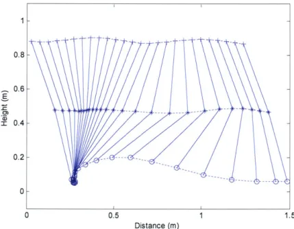
In this thesis, human walking data were used in order to specify the design requirements for the components at the exoskeleton joints. The power profiles for the hip, knee and ankle in the sagittal plane were plotted for a number of sets of gait data (Kirtley, 1998 (old and young); Linskell, 1997; van den Bogert, 2004). The biomechanical data presented in this thesis come from studies where camera systems tracked markers placed on a subject's legs while they walked on a set of force plates. The marker position data and the force plate data are then used to calculate the kinematics and kinetics of movement. Joint power is the dot-product of the moment at the joint and the angular velocity of the distal segment with respect to the proximal segment. Depending on the direction of the movement and the direction of the angular velocity, the power can be either positive or negative. In the biomechanics literature, positive power is called 'power generated', and negative power is called 'power absorbed'.
0 0.8 0.6 0.4 0.2 0 0 0.5 1.5 Distance (m)
Figure 2.6 A plot of the gait data showing the trajectory of the hip, knee and ankle joint
1998 (old)).
(Data from Kirtley,
A conservative estimate of the weight of the exoskeleton and payload was chosen to be 60kg and the normative data were scaled to a 60kg person in order to estimate the torques
and powers required at the joints of the exoskeleton. In estimating the torque and power requirements at the hip joint of the exoskeleton, the normative data were scaled to a
1
-- -- -- -- - -- - -- ---
-1
--135kg person. This was due to the fact that the design goal was to have the actuator at
the hip assist the exoskeleton (60kg) as well as the human (75kg). The human was assisted by means of a thigh cuff attachment between the human and exoskeleton thigh. The pelvic tilt angle was added to the hip angle to yield a single angle which represented the angle between the human torso and the thigh in the sagittal plane. The goal was to design an exoskeleton to assist in load carrying at slow walking speeds. As a result, the data used to extract specifications for actuation at the joints were that for a walking speed of 0.8m/s (Kirtley, 1998).
A number of assumptions were made in the application of the human biomechanical data
to the design of the exoskeleton. The first was that the exoskeleton carried its own weight, power supply and payload. The second assumption was that joint torques and joint powers scaled linearly with mass. This second assumptions seemed reasonable given that increases in vertical ground reaction force have been found to be proportional to increases in the load being carried (Llyod, 2000). The third assumption was that the
exoskeleton would not greatly affect the gait of the wearer.
2.3.1 Hip Kinematics and Kinetics
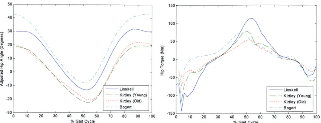
During normal walking, the human hip joint follows an approximate sinusoidal pattern as can be seen in Figure 2.7. The thigh is flexed forward on heel strike and then the hip moves through extension during stance as the body is pivoted over the stance leg in a pendulum-like motion. The range of motion of the hip joint can be seen to vary between
-20 to 45 degrees.
At heel strike there is a sharp increase in hip torque as the leg accepts the weight of body to begin the stance phase. A peak negative hip torque of approximately 130Nm is experienced as the leg accepts load and the body's center of mass is raised. A maximum positive torque of about 1 OONm occurs during the swing phase as the hip muscles provide energy to swing the leg forward.
150 40 1 100 --30 0- - 50 - 20-0 - --10 ---- Linskell ---- Linskell
-20 - Kirtley (Young) -100 -- Kirtley (Young)
-- -Kirtley (Old) --- Kirtley (Old)
- - Bogert Bogert
0 10 20 30 40 50 60 70 80 90 100 0 10 20 30 40 50 60 70 80 90 100
% Gait Cycle % Gait Cycle
Figure 2.7 Hip angle and torque profiles scaled for a 135kg person.
The power profile at the hip as a function of gait cycle is shown in Figure 2.8. On heel strike the hip abductors move from eccentric to isometric to concentric activity, elevating the pelvis in preparation for swing. During mid-stance, eccentric hip flexor activity controls the body being carried forward by momentum. The hip contributes to propulsion as it shifts from eccentric to concentric activity which will advance the extremity into the swing phase by lifting the leg and swinging it forward. This region is the muscular system's second largest contribution of propulsive power during the gait cycle and is often referred to as 'pull-off'.
200 150 - H3 100- HI 50 -~ 0 --50 Linskell -100- Kirtley (Young)_ H2 -- -Kirtley (Old) Bogert -150' 0 10 20 30 40 50 60 70 80 90 10C % Gait Cycle
Figure 2.8 Hip joint power profile scaled for a 135kg person as a function of the gait cycle. HI is a small region of positive power, not always present, which corresponds to concentric hip extensor activity during loading response. H2 is a region of negative power, corresponding to eccentric hip flexor activity during mid-stance. Lastly, H3 is a region of positive power, corresponding to concentric activity in the hip flexors during pre-swing and initial swing.
The hip joint is the preferred location for a non-conservative actuator as proximal mass is less expensive metabolically in walking than distal mass. An actuator could assist by adding power in the HI and H3 regions. The maximum positive power required is approximately 150W and this occurs as the leg is beginning the swing phase. Also from Figure 2.8 it can also be seen that a spring placed at the hip joint could absorb the negative energy in H2 and release it during H3 to assist in swinging the leg forward. In Figure 2.9 an approximate linear relationship can be seen between the hip torque and angle during the stance phase of the walking cycle. The spring constant for such an "extension spring" was estimated as 11 5Nm/rad.
60 + Extension 40 - * Flexion 40-20 - **+ * T 115 * z- 0 + Nm/rad * -20* -40- -60--801 -10 -5 0 5 10 15 20 25 30 35
Hip Angle (Deg)
Figure 2.9 The hip angle plotted versus hip torque for a walking speed of 0.8m/s (Kirtley, 1998 (old)).
A summary of the specifications for actuation at the hip joint of the exoskeleton are
shown in Table 2.1. The approach taken in this thesis was to use a non-conservative actuator at the hip. Although a non-conservative actuator at the hip is heavier than a simple spring, it was believed that it would not be too detrimental to walking metabolism as the mass was proximal. A possible hybrid approach might be to use a small motor in conjunction with the spring in the stance phase to aid the leg further in the swing phase.
Table 2.1 Specifications for the hip joint of the exoskeleton that were extracted from the gait data
Range of Motion -20 deg to 45 deg
Max Joint Velocity 4 rad/s
Max Joint Torque 130 Nm
Max Joint Power 150 Watts
2.3.2
Knee Kinematics and Kinetics
Figure 2.10 shows plots of the angle and torque profile of the knee joint as a function of gait cycle. In early stance there is initial flexion-extension of the knee to help maintain a near horizontal trajectory of the body's center of mass. After the initial flexion-extension the knee remains locked for the remainder of the stance phase. The knee then undergoes flexion of approximately 60 degrees to allow for foot clearance during the swing phase. On heel strike, the knee bends slightly while exerting a maximum negative torque of 30Nm as the leg accepts the weight of the human. This is followed by a large positive extension torque of approximately 50Nm that keeps the knee from buckling during early
stance and also assists in straightening the leg.
0 50 --- Linskell -10- 40 - - - Kirtley (Young) -- -- Kirtley (Old) -20- 30 Bogert -30- \ - 20 --40- - 10 --60 --- Linskell -10 - Kirtley (Young) -70- Kirtley (Old) -20 -Bogert -80 _______________________________-I-__L___L__30___L____ 0 10 20 30 40 50 60 70 80 90 100 0 10 20 30 40 50 60 70 80 90 100
% Gait Cycle % Gait Cycle
Figure 2.10 Knee angle and torque profiles scaled for a 60kg person.
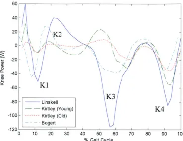
Figure 2.11 outlines the power of the knee as a function of gait cycle. It can be seen that the power is largely negative indicating that the knee absorbs power for the majority of the gait cycle. At heel strike there is a region of negative power followed by a period of positive power as the knee goes through stance flexion-extension. This is followed by a period of negligible joint power as the knee is passively extended. Here the quadriceps are inactive and it is the ground reaction forces, as well as activity in the ankle plantar flexors, that keep the knee stabilized in extension. For a large part of the swing phase the leg has a pendulum like motion with the knee varying the damping to control the swing leg duration.
60 40-20 -60_ KI K3 -80- Linskell - Kirtley (Young) K4 -100 - --- Kirtley (Old) Bogert -120 0 10 20 30 40 50 60 70 80 90 10C % Gait Cycle
Figure 2.11 Knee joint power profile scaled for a 60kg person as a function of gait cycle. KI is a region of negative power, corresponding to eccentric knee extensor activity during the loading response K2 is a region of positive power, corresponding to concentric knee extensor activity during mid-stance. K3 is a region of negative power, corresponding to eccentric activity in the rectus femoris during pre-swing. K4 is
a region of negative power, corresponding to eccentric activity in the hamstrings during terminal swing.
It can be seen in Figure 2.11, that during flexion-extension during early stance, the knee behaves like a spring as there is a region of negative energy followed by a region of positive energy of similar size. Figure 2.12 shows a plot of knee angle vs. torque and a linear relationship can be seem during the stance phase. For the remainder of the gait cycle, the knee acts like a variable-damper to control leg during the swing phase.
10 * Stance Flexion e Stance Extension 5 - + + + + Swing Phase 0- + - -1* -* -~ 0) ++ E --5 + 0 I~ + Kn(AgD Dg -10 + 136 Nm/rad -201 -60 -50 -40 -30 -20 -10 0
Knee Angle (Deg)
Figure 2.12 A plot of knee angle versus knee torque for the walking cycle. During the stance phase there is a linear relationship between torque and angle. It can be seen that the knee behaves primarily as a variable-damper throughout the gait cycle (Kirtley, 1998 (old)).
From the gait data it appears that the ideal actuator for the knee of the exoskeleton is a spring with a variable-damper. The spring would provide a resistive torque at the knee on heel strike as energy is absorbed and this energy is then released to aid in knee extension during stance. During the swing phase, the variable-damper would be engaged to control the swinging of the leg. It should be noted, for walking on a decline or down stairs, the variable-damper would be required during the stance phase to dissipate energy. However, for this thesis a variable-damper mechanism was used without the spring. The damper was able to provide the necessary resistive torque during stance but the negative energy was dissipated as heat.
Table 2.2 Specifications for the knee joint of the exoskeleton that were extracted from the gait data.
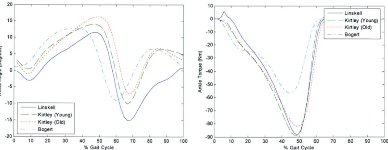
2.3.3 Ankle Kinematics and Kinetics
The ankle joint experiences a range of motion of approximately 15 degrees in both directions during normal human walking. During the mid and late stance phases of walking the ankle eccentric plantar flexor activity creates negative joint torque as the ankle controls the forward movement of the center of mass. The peak torque experienced
by the ankle is approximately 90Nm.
20 10 Linskell 15 - 0 Kirtley (Young) Kirtley (Old) 10 -10 - - Bogert 1 0 - -2 0 -5 - 3 -5-D -30 -_ 0- -40-N \ / 50-K -60 -10 - Linskell -70 - Kirtley (Young) -15 --- Kirtley (Old) -80-Bogert -20 -90 0 10 20 30 40 50 60 70 80 90 100 0 10 20 30 40 50 60 70 80 90 100
% Gait Cycle % Gait Cycle
Figure 2.13 The ankle angle and torque profile scaled for a 60kg person are shown.
Range of Motion 0 deg to 90 deg
Max Braking Torque 50 Nm
The power as a function of gait cycle for the ankle is shown in Figure 2.14. For slow walking the region of negative work, Al, is approximately equal to the region of positive power, A2 suggesting that a spring at the ankle is be a good choice for actuation at the ankle. At faster walking speeds, A2 is significantly larger indicating that a non-conservative actuator is required. However, a heavy actuator at the ankle would be detrimental to walking metabolism due to the large distal mass.
IOU 140 120 100 80 60 40 20 0 -20 -40 I ins - Kirtl --- Kirtl A2 Bog 'I 10 20 30 40 50 60 70 80 % Gait Cycle kell ey (Young) -ey (Old) ert 90 100
Figure 2.14 Ankle joint power profile scaled for a 60kg person as a function of gait cycle. Al is a region of negative power, corresponding to eccentric plantar flexor activity at the ankle during mid-stance and terminal stance. A2 is a region of positive power, corresponding to the concentric burst of propulsive plantar flexor activity during pre-swing.
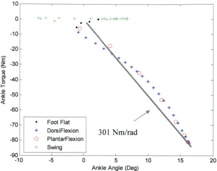
Figure 2.15 shows the ankle torque plotted vs. angle for walking at 0.8m/s. A linear fit yields a spring constant for the ankle of approximately 301Nm/rad for this walking speed. This implies that, for slow walking, a spring could be placed at the ankle of the exoskeleton to store the negative energy during controlled dorsiflexion and later release this to assist in powered plantarflexion. Further, the energy released from such a spring could also help to minimize the negative effects of distal exoskeleton mass.
0 a-0) o .
0-10 0- -10- -20- -30- -40- -50- -60--70_ -80-00n -0o + * * Foot Flat DorsiFlexion 301 Nm/rad + ) PlantarFlexion Swing -10 -5 0 5 10 15
Ankle Angle (Deg)
Figure 2.15 Plot of ankle angle versus ankle torque for the walking cycle. It can b
behaves like a spring during stance at a walking speed of 0.8m/s (Kirtley, 1998 (old)). 20
e seen that the ankle
The summary of the specifications for the ankle joint are shown in Table 2.3. For slow walking speeds a spring is the ideal choice for actuation at the ankle as the energy absorbed during dorsiflexion is almost equal to the positive energy generated during controlled plantarflexion. Based on the ankle data in Figure 2.15 the total energy that is absorbed and then later released is approximately 9J. At faster walking speeds the positive power becomes increasing large and in this case a hybrid actuation approach may be beneficial where a small motor is used in conjunction with the spring. The focus of this thesis is slow walking only.
Table 2.3 Specifications for the ankle joint of the exoskeleton that were extracted from the gait data. z
0
C
C
Range of Motion -15 deg to 15 deg
Max Joint Torque 90 Nm
3 Electro-Mechanical Design of Exoskeleton
The exoskeleton was designed to provide a parallel load path that transferred the weight of the backpack directly to the ground. The exoskeleton had sufficient degrees of freedom to minimize kinematic constraints experienced by the wearer. Component design and selection for the hip, knee and ankle joints was based on the specifications outlined in Chapter 2. The main components of the exoskeleton are shown in Figure 3.1.
Backpack
Hip Actuator Pelvic
Harness
Knee Damper Thigh Cuff
Foot
Ankle Spring Attachment
Figure 3.1 The main components of the exoskeleton.
3.1
Functional Requirements
It can be concluded, from the information outlined in Section 1.1 that there is an advantage to supporting a load that a person is carrying as well as providing them with a forward propulsive force. From the results of the metabolic experiments discussed, as well as the practical considerations of power requirement and noise level, a number of functional requirements for the exoskeleton can be listed. They are,
" The structure must support load of payload
" The structure must be lightweight and in particular have low distal mass
* The architecture must be wearable and not conflict substantially with gait * The exoskeleton must use minimum power
* The exoskeleton must be as quiet as possible
3.2
Exoskeleton Structure
The design of the exoskeleton structure had to address the fact that the structure's primary function was to support the payload and provide the mechanical interface to the operator. A parallel orthotic structure was the basic framework used to transfer the load from the backpack to the ground. The main structural elements consisted of standard prosthetic aluminum tubing. This tubing was used since it is lightweight, rated for human use, and interfaced with standard prosthetic connectors and components.
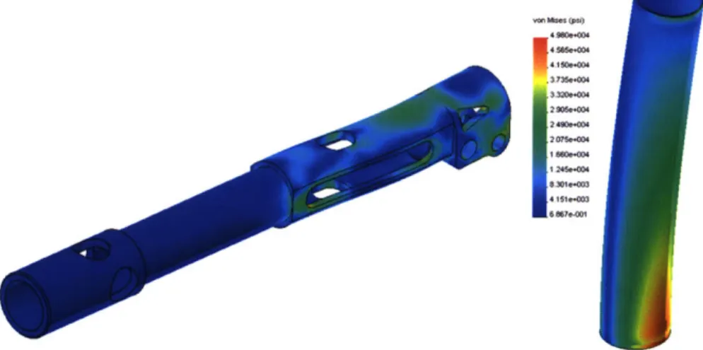
The criteria for sizing the structural elements had to take into consideration the stresses, and also the structural stiffness. Minimizing the size and weight of the structural elements was traded off against maintaining structural stiffness so that the payload could be adequately supported. The strength to weight ratio of the exoskeleton components was maximized using finite element analysis. Free body diagrams were used to determine the boundary conditions that were applied in performing the analysis. Figure
3.2 shows graphical results of a stress analysis in the exoskeleton shank and thigh.
va 12 40 000
[email protected] 030-3
3735-004
33200-OX
24900-04 3.4"
Figure 3.2 Finite element results from testing the exoskeleton thigh and shank.
3.3
Exoskeleton Degrees of Freedom
The exoskeleton was implemented with three degrees of freedom at the hip, one at the knee, and two at the ankle. The joint ranges of motion accommodated normal human walking.
Table 3.1 shows the degrees of freedom of the exoskeleton. The approach taken in the design of the exoskeleton in this thesis was to collocate the exoskeleton and human joints in the sagittal plane. This maximized comfort for the wearer.
Joint DOF Description
Hip 3 Flexion and extension, abduction and adduction, medial and lateral rotation
Knee 1 Flexion
Ankle 2 Flexion and extension, Inversion and eversion Table 3.1 Exoskeleton degrees of freedom.
HIP Flexion/Extension Abduction/Aduction Ankle Flexion/Extension Knee Flexion/Extension Medial/Lateral rotation of leg above knee joint
Figure 3.3 Schematic of exoskeleton structure and degrees of freedom of exoskeleton.
Flexion and extension of the exoskeleton hip was accomplished using a reali-slim Kaydon bearing in a custom housing. A cam mechanism was implemented at the hip joint to enable hip abduction and adduction (Valiente, 2005). The cam mechanism automatically adjusted the exoskeleton leg length so that the human leg could freely abduct and adduct. Medial-lateral rotation of the exoskeleton leg was allowed by means of a rotary joint just above the knee joint. The knee joint of the exoskeleton was a revolute joint. A revolute joint at the ankle allowed for movement in the sagittal plane and a flexible spring steel attachment allowed relative motion between the human and exoskeleton foot in the coronal plane.
Exoskeleton interface to the human
The exoskeleton interfaced to the human via shoulder straps, a waist belt, thigh cuffs, and a shoe connection. A compliant belt interfaced the lower torso to the backpack frame and the backpack's shoulder straps interfaced to the upper torso. The physical connection between the exoskeleton and the human enabled the exoskeleton to passively track the human's leg motion and kept the exoskeleton and human leg joints collocated. A standard military issued backpack, Alice Pack, carried the load. The exoskeleton was attached to the standard military backpack through a harness. The hip joints of the exoskeleton legs were mounted to the harness. There was sufficient clearance between the pelvic harness and the wearer to minimize disturbance to the wearer's gait.
3.4.1
Carbon Fiber Harness
The exoskeleton was attached to the standard military backpack using a harness that allowed for mounting the hip joints of the exoskeleton. The structure was made from carbon fiber and was attached to the backpack such that it maximized stiffness of the structure. Interfacing the exoskeleton to the human was a difficult problem, making it necessary to construct mockups to determine the correct geometry to ensure that the disturbance of gait was minimized.
Figure 3.4 Foam mockup of the exoskeleton harness being tested.
The harness connected rigidly to the backpack frame to transfer the load from the backpack to the exoskeleton. The pelvic harness was made from carbon fiber and the
stiffness to weight ratio was optimized using finite element analysis. The finite element analysis was used in an iterative design process until the regions of stress concentration were minimized and the desired stiffness was obtained. The structure consisted of a hollow core with 1/16th inch thick layer of carbon fiber over it. A box was also incorporated into the harness for electronic part storage while at the same time increasing structural integrity.
30.
Figure 3.5 The stiffness to weight ratio of the carbon fiber harness was maximized using finite element analysis. In a), finite element result for stress in the carbon fiber harness is shown. In b), the structure consisting of a hollow core with 1/16th inch thickness of carbon fiber layer over it is shown.
3.4.2
Thigh brace
To enable the exoskeleton track the human leg and for requisite torques to be applied to the human thigh, a thigh brace was required. This allowed the exoskeleton knee to remain collocated with the human knee and also forced the exoskeleton leg to follow the human leg movement in the coronal plane during abduction and adduction. The custom thigh brace had molded vertical flat sides to allow for attachment to the exoskeleton leg. The cuff was padded and Velcro was used to secure it. A spring steel plate between the exoskeleton leg and the thigh cuff was compliant in the coronal plane and this allowed for small misalignments between the human and exoskeleton leg. The thigh brace was connected to the yaw joint that allowed for medial-lateral rotation of the exoskeleton leg ensuring that it rotated with the human leg.
Foot attach
The exoskeleton foot was attached to the human foot with two pieces of spring steel. The connection was sufficiently rigid so that it kept the exoskeleton foot in line with the human foot and also allowed movement between it and the human foot, increasing comfort during walking.
3.5
Final Assembly
The components for the exoskeleton, excluding the actuators for the hip joint, are shown in Figure 3.6. The carbon fiber harness was attached to the backpack and a waist belt secured it to the wearer. The thigh cuffs attached the exoskeleton thigh to the human thigh and the shimano bike shoes were worn by the wearer.
CF Harness Thigh Brace Shank Exoskeleton -Foot Exoskeleton and Cam Assembly Knee Joint Spring Steel Foot Attach
Figure 3.6 Exoskeleton components prior to assembly.
3.6
Actuation
This section describes the design and characterization of the actuation of the exoskeleton joints in the sagittal plane. A linear series elastic actuator with a DC brushed motor was used for the hip joint, a magnetorheological damper was used for the knee joint and a compression spring was used for the ankle joint. A passive spring for adduction at the hip joint was designed to counter moments from the exoskeleton leg on the wearer.
3.6.1
Hip Series Elastic Actuator Design
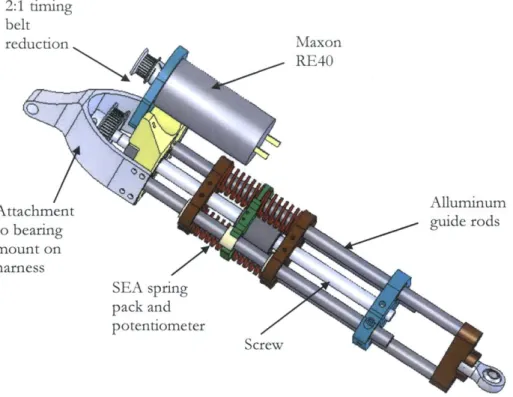
Series elastic actuators (Pratt et al., 1995) were used as they provided a means for implementing lightweight and inexpensive force control in a bandwidth similar to that of natural muscle. The SEA uses a spring in series with the output of the motor as shown schematically in Figure 3.7. The spring acts as a sensor, filter and impedance limiter. For the actuator described in this thesis the ball screw nut was coupled to the output through four compression die-springs and the spring compression was measured with a linear potentiometer.
Torsional Spring
Motor/Gearbox Output
Figure 3.7 Rotary series elastic actuator schematic.
The specifications for actuation at the exoskeleton hip joint outlined in Section 2.3.1 were used to design the series elastic actuator. A 150W Maxon RE40 motor was chosen for its power to weight ratio. The ball screw and nut were Nook Industries products and the springs used were die springs from Century Spring. Since a linear actuator was used, the moment arm at the hip joint and the force output of the actuator determine the hip torque. The actuator had a brushed DC motor driving a 3mm lead ball screw via a 2:1 reduction belt drive. Figure 3.8 shows the main components of the actuator.