Publisher’s version / Version de l'éditeur:
Vous avez des questions? Nous pouvons vous aider. Pour communiquer directement avec un auteur, consultez la première page de la revue dans laquelle son article a été publié afin de trouver ses coordonnées. Si vous n’arrivez pas à les repérer, communiquez avec nous à [email protected].
Questions? Contact the NRC Publications Archive team at
[email protected]. If you wish to email the authors directly, please see the first page of the publication for their contact information.
https://publications-cnrc.canada.ca/fra/droits
L’accès à ce site Web et l’utilisation de son contenu sont assujettis aux conditions présentées dans le site LISEZ CES CONDITIONS ATTENTIVEMENT AVANT D’UTILISER CE SITE WEB.
13th International Conference on Wind Engineering (ICWE13). Programme Book: 10-15 July 2011, Amsterdam, Netherlands, 2011-07-10
READ THESE TERMS AND CONDITIONS CAREFULLY BEFORE USING THIS WEBSITE. https://nrc-publications.canada.ca/eng/copyright
NRC Publications Archive Record / Notice des Archives des publications du CNRC : https://nrc-publications.canada.ca/eng/view/object/?id=0181ff5e-1900-4c16-9d31-b5436545d127 https://publications-cnrc.canada.ca/fra/voir/objet/?id=0181ff5e-1900-4c16-9d31-b5436545d127
NRC Publications Archive
Archives des publications du CNRC
This publication could be one of several versions: author’s original, accepted manuscript or the publisher’s version. / La version de cette publication peut être l’une des suivantes : la version prépublication de l’auteur, la version acceptée du manuscrit ou la version de l’éditeur.
Access and use of this website and the material on it are subject to the Terms and Conditions set forth at
Evaluating wind effects of commercial roofs: North American advancements
http://www.nrc-cnrc.gc.ca/irc
Eva lua t ing w ind e ffe c t s of c om m e rc ia l roofs -- N ort h Am e ric a n a dva nc e m e nt s
N R C C - 5 3 9 3 1
B a s k a r a n , B . A . ; M u r t y , B . ; P r e v a t t , D .
J u l y 2 0 1 1
A version of this document is published in / Une version de ce document se trouve dans:
13th International Conference on Wind Engineering, Amsterdam, Netherlands, July 10-15, 2011, pp. 1-4
The material in this document is covered by the provisions of the Copyright Act, by Canadian laws, policies, regulations and international agreements. Such provisions serve to identify the information source and, in specific instances, to prohibit reproduction of materials without written permission. For more information visit http://laws.justice.gc.ca/en/showtdm/cs/C-42
Les renseignements dans ce document sont protégés par la Loi sur le droit d'auteur, par les lois, les politiques et les règlements du Canada et des accords internationaux. Ces dispositions permettent d'identifier la source de l'information et, dans certains cas, d'interdire la copie de documents sans permission écrite. Pour obtenir de plus amples renseignements : http://lois.justice.gc.ca/fr/showtdm/cs/C-42
Evaluating wind effects of commercial roofs
North American advancements
Baskaran, A
a, Murty, B
b, Prevatt, D
c, Dixon C
c, Datin, P
ca
National Research Council of Canada, Ottawa, Ontario, Canada, [email protected] b
Dept. of Civil Engineering, University of Ottawa, Ontario, Canada c
Dept. of Civil and Coastal Engineering, 365 Weil Hall, University of Florida, USA
ABSTRACT
The North American roofing community has made significant advancements, summarized in this paper, in the dynamic wind evaluation of commercial roofs through a North American roofing consortium, Special Interest Group for the Dynamic Evaluation of Roofing Systems (SIGDERS). Investigations and interactions with industries have identified several research challenges for wind engineers as listed in this paper.
1 INTRODUCTION
A building’s roof protects its occupants and contents from environmental conditions such as
rain, wind and solar radiation. Therefore, it has to be designed with utmost care to ensure func-tional effectiveness and maintenance under those conditions. Roofing systems generally can be divided into two groups: low slope and steep slope roofing systems. Typically, residential roofs belong to the steep slope roof system group whereas, the commercial or industrial buildings such as, office buildings, warehouses, retail buildings, plants and factories, often have low slope roofs. This paper focuses on wind effects on commercial (low slope) roofs and its North American advancements.
2 MARKET SHARE OF LOW SLOPE ROOFING SYSTEM BASED ON COVERINGS
The roofing community in North America has undergone much change over the last 25 years along, with advances in material science, computer-aided designs and engineering applications.
According to a 2000 market survey for the Canadian Roofing Contractors’ Association
(CRCA), the modified bitumen roofing systems have dominated the low slope roof market in Canada by occupying 55% of shares. Data from the National Roofing Contractors Association (NRCA) in the US shows that the single-ply low slope roofs have 40% of the market share.
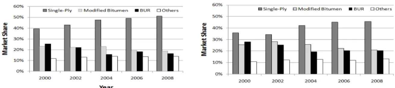
Figure 1 shows the changes in the market share for low-slope roofs based on the 2008–09
NRCA market survey. During these eight years, single-ply roofing for new and re-roofing con-structions have been increasing and clearly have the largest market share in commercial roof-ing.
3 LOW SLOPE ROOFS BY ATTACHMENT
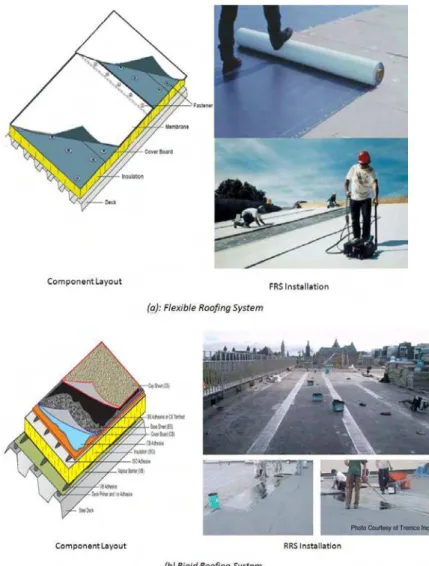
In accordance with the attachment methods of the roof components, conventional roofing can be grouped into two categories: Flexible Roofing System (FRS) and Rigid Roofing System (RRS) as shown in Figure 2. In a FRS, components such as, insulation and cover boards, are integrated using mechanical fasteners. In a RRS, components are integrated using adhesives. When wind flows over a low-slope roof, it creates a suction which exerts an uplift force on the roof system. FRS and RRS can react differently when exposed to the same magnitude of wind uplift due to their particular load transferring mechanisms or response. These reactions are caused by different attachment methods, configurations, and application technologies.
Figure 2. Typical view of commercial roofs
4 RESPONSE OF FLEXIBLE AND RIGID ROOFS UNDER WIND EFFECTS
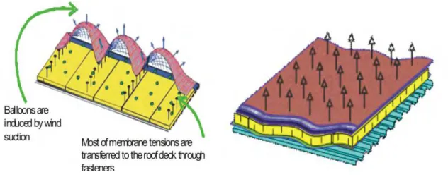
In FRS, moderate-to-strong winds can cause the membrane to lift and billow between attach-ment points or rows. In Figure 3, the reaction to wind uplift of FRS is simplified. The billow height is determined by the combination of wind load, the fastener row spacing, the load-strain modulus of the membrane, and the presence of an air retarder/vapour barrier in the roof system
(Baskaran et al, 1997). The membrane force is transferred directly to the membrane fasteners.
the insulation attachment, the insulation is not really exposed to a great deal of wind uplift
forces. In contrast to the wind uplift response of the FRS, the RRS responds as a “whole” to
wind uplift as also shown in Figure 3. All RRS components are bonded together and therefore,
work together as a “whole” to resist the wind uplift load without billowing. The wind uplift
loads applied on the roof system are fully transferred from the membrane to the other layers underneath in sequence through adhesive bonding. In other words, the substrate layer of mem-brane, namely the insulation, resists the upper membrane pressure and passes to the next
under-lying layers if, there are no component differential deformations taken place.
Figure 3. Wind effects on flexible (left) and rigid (right) roofs
5 NORTH AMERICAN ADVANCEMENTS IN WIND UPLIFT RESEARCH
The North American roofing community has made significant advancements in the dynamic wind evaluation of commercial roofs through a North American roofing consortium, Special Interest Group for the Dynamic Evaluation of Roofing Systems (SIGDERS). In 1994, SIGD-ERS was established to develop wind uplift test standards for roofing systems under dynamic conditions. This section summarizes the advancements made during the last sixteen years
(1994 – 2010), namely, the development of a test method for FRS and the enhancement of the
developed test method to include RRS.
5.1 Development of a new dynamic test method for membrane roofs
In the 1990s, no test method existed to evaluate commercial roofs under a dynamic
environ-ment. The SIGDERS’ test method for the FRS was developed based on wind tunnel studies of
full-scale roof assemblies. Under simulated wind flow conditions, roofing systems were tested in the 9 m by 9 m NRC wind tunnel. The roofing systems were 3 m by 3 m in size with full-scale roofing components. To represent the FRS, two series of wind tunnel investigations were carried out using two distinct roofing membranes. The first series dealt with a reinforced PVC membrane and the second, with a non-reinforced EPDM membrane. Additional details of the wind tunnel are presented in Savage et al. (1996). To account for the RRS, wind tunnel testing was recently conducted with similarities, as that of the FRS, in the geometry of the model,
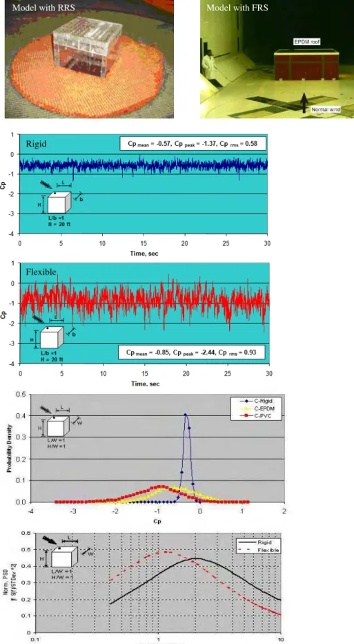
pressure tap locations and wind conditions (Murty, 2010). Figure 4 compares the FRS’
re-sponse with the RRS’, for a similar location (corner zone) and tested under open country
expo-sure with 45 degree wind angle for the building height (H) / building width (W) ratio equal to 1.
Time history: Pressure fluctuations were higher in the case of FRS than those of the RRS
(CPrms: 0.93 vs 0.58). Higher magnitude in both peaks and averages were also measured in the case of the FRS.
Probability Distribution: The variation of the Cp data for flexible roof was higher than the
Cp data for rigid roof. In the FRS, the Cp varied from -3.5 to 1.25 with the probability of oc-currence of any value less than 0.1.The variation is caused by the method of attachment used for the membrane. The FRS uses membranes that are attached using fasteners to a substrate at discrete locations. This causes the membranes to flutter during wind action. The fluttering ef-fect creates a higher Cp data variation that represents fluctuations on the roof. In the RRS, membrane fluttering does not exist hence, creating a lower Cp data variation. The Cp data vari-ation can influence the number of cycles (gusts) used for the load cycles. The PDF of the Cp data series found in this study were non-Gaussian as the curves were negatively skewed espe-cially, at the corner and perimeter zones. For the field zone, the rigid data series appeared to be Gaussian and, non-Gaussian for the flexible data. Similar observations were also made by Sta-thopoulos (1980).
Spectral Analysis: Spectral peaks of the flexible roof were always found consistently higher
than those of the rigid roof. The PSD peaks recorded for both models occurred at the frequency lower than 4 Hz. From the above analysis and observations, it is clear that the system response of the rigid and flexible roofs due to wind actions is different. The difference in roof system responses is caused by the membrane fluttering effect can translate into differences in the wind uplift resistance.
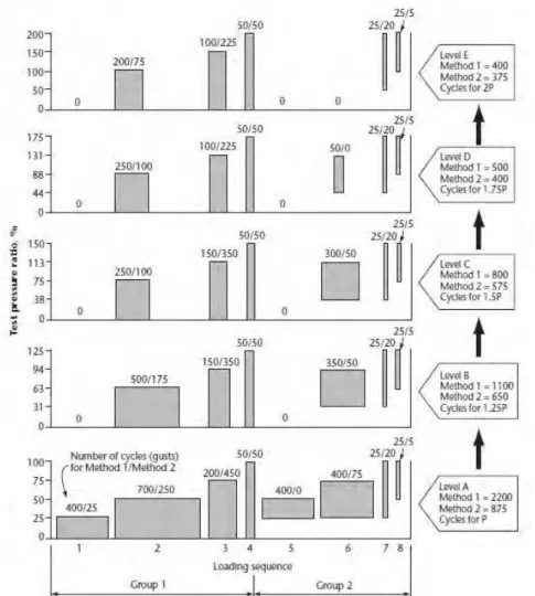
To develop a laboratory procedure for certifying full-scale roofing assemblies, the above da-ta was reorganized into different pressure zones along with their respective number of cycles using a rain flow counting method. Figure 5 shows the developed load cycle. Eight pressure zones were selected under two groups. Group 1 represents the wind-induced suction over a roof assembly consisting of four sequences where, the pressure level alternates between zero and a fixed pressure. Group 2 represents the effects of exterior wind fluctuations combined with a constant interior pressure on a building. In Group 2, a constant minimum static pressure is ap-plied to the roof system and gusts are apap-plied above this pressure. Group 2 mimics membrane tension effects aimed to simulate fatigue at the fastener locations or adhesive interface as the roof membrane is lifted by the static pressure. Technical details on the development of the load cycle are documented in Baskaran et al (1999) for the FRS whereas the RRS details are pre-sented by Baskaran et al (2010).
For standardized test methods, not only is the development of the load cycle (Figure 5) criti-cal but, the guidelines for the specimen size is also important. Prevatt et al (2008) conducted wind uplift tests on mechanically-attached single ply membranes using several test chamber sizes, varying in aspect ratios. They found that the specimen’s aspect ratios and fastener spac-ing ought to be considered in order to accurately predict wind uplift capacity of sspac-ingle-ply membranes using standard test results. When the chamber aspect ratio (specimen width to fas-tener row ratio) was below 1.85, the measured fasfas-tener load at failures was well below the cal-culated load values. This resulted in an overestimation of membrane or fastener strength using the conventional method to calculate failure load (failure pressure x tributary area). The load-sharing between the chamber boundaries and fasteners resulted in inconsistent results. It is im-portant that standards and testing organizations be aware of this and, also that using larger spe-cimens alone may not always eliminate the aspect ratio concerns which can lead to erroneous results (Dixton et al, 2010).
It was found that specimens with aspect ratios greater than 2.0 provided reasonable agree-ment between calculated failure load and measured failure load. Following similar procedures, CSA A123.21-10 Standard developed the correction factor curves. These curves offer solutions
by correcting the wind uplift performance of a system tested in a smaller table to an appropriate required table width.
Figure 4. Comparison of system response – rigid vs flexible roofs
Model with RRS Model with FRS
Rigid
Figure 5. Dynamic wind load cycle for flexible roofing system (Method 1) & rigid roofing system (Method 2)
5.2 Advancement in Low Slope Metal Roofs
The membrane is used as the waterproofing component in the above discussion on FRS and RRS. Commercial roof assemblies can also have the metal sheet act as the waterproofing cov-er. A structural standing seam metal roofing (SSMR) is a system of 30.5 to 61 cm. (12 to 24 in.) wide metal panels laid side by side and mechanically seamed to adjacent panels to form watertight joints. The performance of SSMR system relies on the integrity of the seamed joints. The dominant failure mechanism is clip separation from the seam. Seam failure can be attri-buted to several factors: 1) Poor detailing of the eave edge condition where uplift pressures are highest. This occurs when clips are spaced too far from the roof edge. 2) Weakening of seam due to pressure variation. Under wind load, the panels deflect upwards, rotating about their fixed edges. The low plasticity limit of the thin metal panels allows permanent deformations to take place at the seamed joints. This has a prying effect on the seam, working it loose from the clip by either opening or horizontally translating the seam. Upward deflection of the panels causes rotation along their fixed edges. Blow-off occurs when the panel disengages from the seam. 3) Internal pressurization of the building due to failures of windows, doors, garages, etc. Application of this positive force on the underside of the roof has an additive uplift effect on the roof. The single-layer construction of SSMR makes it vulnerable to pressurization.
Researchers at the University of Florida conducted wind uplift pressure tests on SSMR sam-ples (Dixon et al, 2011). The objective was to determine the boundary condition effects on the structural load distribution among clip fasteners. Load cells provided the measured fastener loads which were compared with assumed loads (defined as tributary area multiplied by
cham-ber pressure) and, an excellent agreement was obtained for the field test (no restrained bounda-ries). The results suggested an empirical design method can be developed to estimate clip
fas-tener loads at or near roof corners or edges. Clip fasfas-tener loads (Lf) were normalized to form
the unitless quantify, C, (given in Equation 1), by dividing by it by the product of chamber pressure (P), and the distance of clips from two closest edges, say gable edge (X) and eave edge (Y).
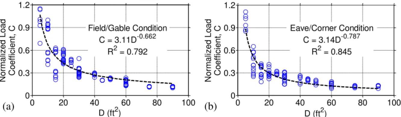
(1) Test results were used to develop the normalized load coefficient (C), which was plotted against the product of the eave to edge distance by the gable to edge distance labeled D (=X·Y). A regression analysis was performed and it was observed that the field and gable boundary conditions produced nearly identical normalization results (Figure 6a) as, did the eave and cor-ner boundary conditions (Figure 6b). These two graphs provide a reasonable prediction of the clip fastener loads based upon their distances away from the boundary.
Figure 6. Regression of normalized load coefficient with the distance from both the eave and gable edges com-bined for the (a) field/gable edge and (b) eave/corner conditions (1 ft = 0.3 m)
These graphs and the empirical approach can be used to predict clip fastener loads, if the di-mensions (purlin spacing, panel width) of the SSMR system are known. An approach for doing this, with any appropriate purlin width (i.e., 458, 610, 812 mm [18, 24, 32 in.]), is pro-posed in Equation 2 presented below:
(2) where: A is a regression constant (shown in Figure 1); n is the power law exponent (shown in
Figure 1); Wp is the individual panel width (ft); and Sp is the purlin spacing (ft). The predicted
fastener load would then be calculated as shown in Equation 3:
(3) This research is suggesting that a more efficient structural design approach for SSMR panels in the edge and corner regions of a roof may be possible since, the exterior clip fastener load is typically less than half the load carried by the interior fasteners. The empirical method pro-posed for predicting the loads on clip fasteners installed near roof boundaries requires further experimental validation but has promise as a practical design tool for SSMR systems. It was found that structural design of edge fasteners may be somewhat overlooked in current design approaches and that this may be related to predominance of edge failures observed after strong wind events. 0 20 40 60 80 100 0 0.3 0.6 0.9 1.2 D (ft2) No rm a lize d L o a d Co e ff ici e n t, C Field/Gable Condition C = 3.11D-0.662 R2 = 0.792 0 20 40 60 80 100 0 0.3 0.6 0.9 1.2 D (ft2) No rm a lize d L o a d Co e ff ici e n t, C Eave/Corner Condition C = 3.14D-0.787 R2 = 0.845 (a) (b)
5.3 Technology Transfer through Standardization
Roof system component manufacturers provide design resistance values for their systems based on uplift testing. It is critical to use a test method that provides a meaningful measure of the up-lift performance of the system. SIGDERS’ goal was to develop a method that would: (1) mimic real wind effects; (2) achieve failure modes observed under real conditions; (3) be easier to ap-ply in the laboratory than existing tests; (4) allow for variation in roof design; (5) produce re-sults quickly and (6) conform to local standards.
Based on this technology advancement, a new North American test standard was adopted
and published by the Canadian Standards Association (CSA A123.21-04 – Standard Test
Me-thod for the Dynamic Wind Uplift Resistance of Mechanically Attached Membrane Roofing Systems). The standard has been recently enhanced by including the findings of the RRS (CSA
A123.21-10).To assist roof designers and manufacturers to evaluate and specify membrane roofs under dynamic environment; this new development has also been proposed to be refe-renced in the national building code of Canada (NBCC 2015).
6 RESEARCH CHALLENGES TO THE WIND ENGINEERS
This paper summarized the advancements in the North American wind uplift resistance evalua-tion procedures. During these two decades of investigaevalua-tions and interacevalua-tions with industries, several research challenges were identified for wind engineers. As presented in Figure 1, ad-vancements in the roof coverings are rapid and market penetrations are significant. However, the wind tunnel methodology developed over the past two decades is less appropriate to quanti-fy wind induced loads on roof coverings. Data used for Figure 4 came from two different wind tunnels (i.e. for a rigid membrane case, a model scale of 1:400 was used and for a flexible membrane roof, a model scale of 1:50 was used). Tanaka et al (1999) studied the effect of scale magnification on wind loads:
How to quantify the differences in the wind loads between rigid versus flexible roofs? What is the role of the roof membrane flexibility on the wind induced roof covering
loads?
How to model the roof covering flexibility in the case of membrane roofs and thin met-al elastic deformation in the case of metmet-al roofs?
In doing so, how one can maintain boundary layer flow in the wind tunnel without in-troducing Reynolds number effect?
The authors are looking forward to present these research topics and lively discussions at the conference.
7 REFERENCES
Baskaran, A., Chen, Y., Vilaipornsawai, A., 1999. A new dynamic wind load cycle to evaluate flexible membrane roofs. Journal of Testing and Evaluation 27(4), 249-265.
Baskaran, A., Murty, B., Tanaka, H., 2010 (accepted). Generalized load cycles for dynamic wind uplift evaluation of rigid membrane roofing systems. Journal of Wind and Structure.
Baskaran, B.A., Paroli, R.M., Booth, R.J., 1997. Wind performance evaluation procedures for roofing systems current status and future trends. 5th International Conference on Building Envelope Systems and Technology, Bath, U.K., pp. 37-52.
CSA A123.21-10, 2010. Standard test method for the dynamic wind uplifts resistance of membrane-roofing
sys-tems. Canadian Standards Association (CSA), Toronto, ON.
Dixon, C.R., Prevatt, D.O., 2010. What Do We Learn from Wind Uplift Tests of Roof Systems?, Structural Engi-neering Institute’s 2010 Structures Congress joint with the North American Steel Construction Conference, Orlando, Florida.
Dixon, C. R., Prevatt, D. O., Datin, P. L., 2011 (accepted for publication). Influence of edge restraint on clip fas-tener loads of standing seam metal roof panels. Journal of ASTM International
Murty, B., 2010. Wind Uplift Performance Evaluation of Adhesive Applied Roofing Systems. Ph.D. Thesis, De-partment of Civil Engineering, University of Ottawa, Ottawa, Canada.
National Research Council Canada, 2010. National Building Code of Canada user’s guide - Structural commenta-ries. NRCC, Ottawa, Ontario, Canada
National Roofing Contractors Association (NRCA), 2008–09. NRCA market survey.
Prevatt, D. O., Schiff, S. D., Stamm, J. S., Kulkarni, A. S., 2008. Wind uplift behavior of mechanically attached single-ply roofing systems: The need for correction factors in standardized tests. Journal of Structural Engi-neering, 134(3), 489-498.
Savage, M.G., Baskaran, B.A., Cooper, K.R., Lei, W., 1996. Pressure distribution data measured during the No-vember 1994 Wind Tunnel tests on a mechanically-attached, PVC single-ply roofing system, pp. 133, (LTR-A-003) (Ref Ser TL570 R425 LTR-(LTR-A-003)
Stathopoulos, T., 1980. PDF of wind pressures on low-rise buildings. Journal of Structural Division, ASCE(106), 973-990.
Tanaka, H., Ghariani, S., Baskaran, B.A., Savage, M.G., 1999. Wind pressure measurements on flat roofs using scaled models. 10th International Conference on Wind Engineering into the 21st Century, Copenhagen, Den-mark, Volume 2, 1195-1202.