Publisher’s version / Version de l'éditeur:
Simposio de Metrologia 2010, pp. SM2010-S5A-1-1-SM2010-S5A-1-1-5,
2010-10-27
READ THESE TERMS AND CONDITIONS CAREFULLY BEFORE USING THIS WEBSITE. https://nrc-publications.canada.ca/eng/copyright
Vous avez des questions? Nous pouvons vous aider. Pour communiquer directement avec un auteur, consultez la
première page de la revue dans laquelle son article a été publié afin de trouver ses coordonnées. Si vous n’arrivez pas à les repérer, communiquez avec nous à [email protected].
Questions? Contact the NRC Publications Archive team at
[email protected]. If you wish to email the authors directly, please see the first page of the publication for their contact information.
Archives des publications du CNRC
This publication could be one of several versions: author’s original, accepted manuscript or the publisher’s version. / La version de cette publication peut être l’une des suivantes : la version prépublication de l’auteur, la version acceptée du manuscrit ou la version de l’éditeur.
Access and use of this website and the material on it are subject to the Terms and Conditions set forth at
AC-DC transfer difference standards and calibrations at NRC Canada
Filipski, Piotr S; Boecker, Michael
https://publications-cnrc.canada.ca/fra/droits
L’accès à ce site Web et l’utilisation de son contenu sont assujettis aux conditions présentées dans le site LISEZ CES CONDITIONS ATTENTIVEMENT AVANT D’UTILISER CE SITE WEB.
NRC Publications Record / Notice d'Archives des publications de CNRC:
https://nrc-publications.canada.ca/eng/view/object/?id=2230c54f-0c83-4735-9c1f-0cc9b6e0b6ff https://publications-cnrc.canada.ca/fra/voir/objet/?id=2230c54f-0c83-4735-9c1f-0cc9b6e0b6ff
Piotr S. Filipski, Michael Boecker
Institute for National Measurement Standards, National Research Council Canada 1200 Montreal Rd. Bldg. M 36, Ottawa, Ontario, Canada K1A 0R6
Phone: 613 993 2313 Fax: 613 952 1394 E mail: Peter.Filipski@nrc cnrc.gc.ca
The paper presents the National Research Council (NRC) activities to establish and maintain ac dc transfer difference standards of voltage and current at the lowest achievable uncertainty levels. It describes the AC Josephson Voltage Standard, a quantum effect based standard of ac voltage based on pulse driven Josephson junction arrays, recently introduced at NRC.
Over the last several years, a significant effort has been undertaken at the National Research Council (NRC) to establish ac dc transfer difference standards of voltage and current at the lowest achievable uncertainty levels. The primary standards have been re evaluated. The working standards based on thermal voltage converters (TVC), and voltage range extenders, were redesigned. The NRC ac dc comparators were fully automated. The current range extenders, ac dc shunts, were custom built, expanding calibration ranges in current and frequency, and significantly reducing uncertainties. These efforts have been successfully validated by NRC participation in all CCEM Key Comparisons of the ac dc transfer difference: CCEM K6.a – ac dc transfer difference at the lowest uncertainty level (less than 1 =V/V), CCEM K6.c – at high frequency (3 V, 1 MHz to 100 MHz), CCEM K9 – at high voltage, (200 V to 1 kV, 1 kHz to 100 kHz), CCEM K11 – at low voltage (10 mV to 100 mV, 1 kHz to 1 MHz), and CCEM K12 – current (10 mA and 5 A, 10 Hz to 100 kHz).
Recently, in a close cooperation with the National Institute of Standards and Technology (NIST), USA, NRC has established a prototype ac Josephson Voltage Standard (ACJVS) based on a pulse driven Josephson junction array. Our objective is to integrate this standard into the NRC system as the primary standard of ac dc transfer difference.
The NRC primary standard of ac dc transfer difference is a group standard, a set of four 20 mA multijunction thermal voltage converters (MJTC). They have been manufactured by a Canadian
company, Guildline Instruments, closely following a design developed by Wilkins at the National Physical Laboratory, UK, [1]. The ac dc transfer difference of these converters has been evaluated theoretically. The four members of the group have been mutually compared at different voltage and current levels. Over the years they were compared to other MJTCs (manufactured by PTB, Germany), and tested as voltage and current converters using two different Fast Reversed DC Sources (both manufactured by AIST, Japan). As a result of these in depth evaluations, a value of 0.0 =V/V, with an extended uncertainty of 0.4 =V/V, was assigned to the average ac dc transfer difference of this group of MJTCs. The frequency range in which the MJTCs can be considered practically errorless extends from 20 Hz to 5 kHz. The converters serve as primary standards of voltage ac dc transfer difference at approximately 1 V (when used as voltage converters) and current ac dc transfer difference at (10 to 20) mA (when used as current converters).
! " !
The frequency range of the NRC working standards is extended by comparing them to a Calorimetric Thermal Voltage Converter (CTVC). This converter, originally designed at NRC, has a calculable and flat frequency characteristic between 1 Hz and 100 MHz. Its thermoelectric ac dc transfer difference is less than 5 =V/V. A simplified schematic of the converter is shown in Fig. 1. The CTVC has been built around an internal tee. A calculable wideband thermal voltage converter was assembled at the end of one arm of the tee. The second arm of the tee, terminated by a type N female connector, has been designed to have the same electrical parameters as the arm of a type N female tee. During calibrations, the converters compared to the CTVC are attached
to this arm. The heater of the reference TVC is a miniature microwave rod resistor, mounted at the end of a short coaxial line. The stainless steel coaxial line, copper plated at the conducting surfaces, thermally insulates the heater from the body of the converter. The temperature of the resistor is sensed by a thermopile: 100 thermocouple junctions manufactured by partially copper plating a spiral of constantan wire.
The mechanical design of the converter is very simple, and its frequency characteristic can be calculated. However, the thermoelectric ac dc transfer difference of the CTVC is not negligible and is level dependent. The converter is therefore calibrated at low frequency, 1 kHz, using a reference MJTC. This low frequency ac dc transfer difference is then added to the calculable frequency dependent component of the ac dc transfer difference.
The CTVC is small, easily transportable and mechanically stable. It is mostly used as a standard voltage converter with a calculable frequency characteristic, for voltages between 1 V to 2 V, and also as a standard current converter. We have used it as a traveling standard in international comparisons with the National Metrology Institutes of the USA, the Netherlands, Germany, [4], Mexico and Japan.
# ! " " $
The voltage range of the working standards has been extended upwards to 1 kV by a set of custom range resistors, frequency compensated for a maximum flatness in the operating range of 10 Hz to 1 MHz. At the highest voltage level, 0.5 kV to 1 kV, we use a commercial high voltage resistor with a
dedicated thermal voltage converter. For calibration of lower voltages, down to 2 mV, we use commercial micropotentiometers and a commercial thermal transfer standard, the Fluke model 792A. An original technique, minimizing the uncertainty of comparison, was developed at NRC to transfer the value of the ac dc transfer difference from the volt level, the operating voltage range of the thermal voltage converters, to the millivolt level.
The NRC ac dc transfer voltage and current comparators have also been assembled in house, [5]. The commercial instruments such as generators, nanovoltmeters and amplifiers, are controlled via the IEEE 488 bus. However, the custom built hardware and the IEEE 488 bus controller communicate with the computer through the serial bus USB. The controlling software has been written in Visual Basic. We are in a process of rewriting it in LabView. The comparison between two thermal voltage converters or two current shunts is fully computerized.
While TVCs still remain the most accurate standards of ac dc transfer difference, the less accurate but much more user friendly electronic instrumentation, based on digital sampling converters or integrated circuit rms dc converters, is used in industry. An electronically aided thermal voltage standard, such as Fluke model 792A, spans the gap between these two applications, and is a good compromise when the ultimate accuracy is not required. It is very stable, and reliable, and was very successfully used as a traveling standard in international comparisons, such as piloted by CENAM, Mexico, in the SIM comparison of ac dc voltage transfer difference, [6]. The NRC has automated the calibration of the Fluke 792A, by designing computer controlled stepping motor range changing. The automated calibration of a Fluke 792A at 312 points is time and cost efficient. Only a test at the highest range requires a short physical intervention of the operator, for the addition of a 1 kV range resistor.
%
The NRC ac dc current transfer difference standards consist of thermal converters and wideband ac shunts. All shunts have been built in house, either from discrete resistors or from a resistive foil. Depending on the current range, three different configurations were used.
For low currents, (10 to 50) mA, shunts were built using surface mount resistors arranged in a star like
!
configuration on a single sided printed circuit board attached to an output connector (type N female). This assembly, together with an input connector, is mounted in a small component box.
Shunts for medium range currents, (0.5 to 10) A, were assembled from a number of bulk metal foil resistors. The structure of each shunt consists of three printed circuit board plates, two output plates and one input plate, connected by a number of ribs. The multiple resistors of each shunt, 112 for the largest shunt of 10 A, are soldered in parallel between the output plates, around their outside perimeter. The input plate is removed from the output plates by the length of the ribs. Each linking rib supplies to the corresponding resistors only a fraction of the total current. An example of a commercial shunt of a similar construction is shown in Fig. 2.
If a large number of parallel resistors is used, a high power shunt can be assembled from precise, low power components. By spatially separating the large input current connection from the output voltage leads, and supplying particular resistors separately through the dedicated ribs, one can considerably limit the electromagnetic coupling between the input and the output, otherwise a source of a significant shunt error.
The four high current shunts, (20, 40, 80 and 100) A, are of a cylindrical coaxial design. They have been manufactured in cooperation with BEV, Austria. Each shunt consists of three coaxial foil cylinders mounted between four copper plates (two input and two output plates), on a glass fiber epoxy cylinder.
The middle cylinder, the resistor of the shunt, is manufactured from a thin manganin foil. The two remaining cylinders are made of a copper foil. The outside cylinder creates the return path for the input current. The inner most cylinder serves as the high voltage output potential lead. Fig. 2 shows NRC 100 A coaxial shunt during calibration of a commercial shunt.
Details of construction of the NRC standard shunts are fully described in [7] and [8].
The presented shunt set is used in the frequency range of 10 Hz to 100 kHz. The ac dc transfer differences of the shunts in the set are lower than 100 IJ/J at 100 kHz. At this frequency, the customer shunt calibration uncertainty varies between 10 IA/A for a 10 mA shunt to 50 IA/A at 100 A for a 100 A shunt.
& ' ! "
The primary standards of dc voltage and resistance are based on quantum effects, the Josephson effect and the quantum Hall effect. Only the primary ac voltage standard relies on an artifact, a multijunction thermal voltage converter, the parameters of which depend on the fabrication, not on fundamental constants. Lead by the NIST, a significant effort, has been undertaken by the international community to extend application of the Josephson effect based circuits to the realization of a quantum primary standard of the ac voltage. Two methods of ac voltage synthesis are being pursued: a step wise synthesis of an ac voltage using programmable Josephson junction arrays, and a pulse modulation synthesis, using pulse driven Josephson arrays. NRC has established, in cooperation with NIST, a prototype ac Josephson Voltage Standard (ACJVS) based on a pulse driven Josephson junction array.
The operation of a pulse driven ACJVS is based on a pulse quantizing property of the Josephson junction. A Josephson junction excited by a short pulse of an appropriate amplitude and duration will respond with a perfectly quantized voltage pulse. The time integrated area of such a voltage pulse is given by the ratio of two fundamental constants
"# , the Planck constant and the charge of an
electron . The polarity of the quantum accurate Josephson pulse is changed by changing the polarity of the exciting pulse. The exciting pulse does not have to be very accurately known or formed, as long as it is “good enough” to stimulate the junction response. By modulating the density of
$ ! % % &
' ( %
these exciting but “imperfect” pulses, one can synthesize a quantum accurate ac voltage, Fig. 3. To increase the generated voltage, a large number of junctions connected in series is excited simultaneously.
The NIST pulse driven ACJVS has been described in [9], a detailed list of literature is given in a review paper [10].
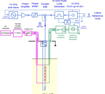
Fig. 4 shows the schematic of the pulse driven ACJVS, a photograph of the NRC system is shown in Fig. 5. At the heart of the system is a superconducting chip containing two independent arrays of 5120 Josephson junctions. The chip is mounted in a cryoprobe and placed in a liquid helium Dewar. Each array can generate up to 110 mV of low frequency rms ac voltage; 100 mV in ordinary applications. Two arrays can be connected in series to generate 200 mV. The exciting pulses are formed by combining the output of a 10 GHz Pulse Code generator with a 15 GHz sinewave generator in a 6 dB stripline directional coupler. The proper timing between these two signals is achieved by shifting the 15 GHz sinewave phase. The array is galvanically insulated from the directional coupler by a DC block (inner and outer capacitors). These capacitors attenuate the low frequency component of the exciting pulses, shown in Fig. 3, top as a sinewave. The exciting pulses are
&
( )
reconstructed to their proper form by reinserting the low frequency component from a separate arbitrary waveform generator, followed by a current amplifier. The arbitrary waveform generator has to be synchronized with the Pulse Code Generator and its phase and amplitude adjusted to accurately replace the attenuated signal.
The output of an array is connected to a room temperature cryoprobe head through a twisted pair copper wire. The output voltage can be then applied to a tested instrument, such as a thermal transfer standard Fluke 792A. In the NRC system, usually a small 6 MHz Low Pass RC Filter (LPF) and a coaxer (equalizer) is inserted between the ACJVS output and the input of the tested instrument.
One of the factors limiting the accuracy of the ACJVS is an error due to the considerable transmission line length, over 1.5 m, between the quantum accurate voltage reference plane at the array output and the input of the instrument under test. This frequency dependent probe leads error is relatively large and requires correction. It can be determined either theoretically or experimentally, [10]. The 6 MHz LPF has been adjusted to partially compensate the probe leads error. It additionally filters out residual high frequency components of the array output voltage. The coaxer suppresses common mode error voltage.
* &
The thermal voltage standard was compared to the ACJVS at (2, 10, 20, 100, 200) mV in the frequency band from 2.5 kHz to 100 kHz (and up to 1 MHz with reduced accuracy). At 100 mV and 2.5 kHz, the ACJVS and TVC results agree better than 1 IV/V, [11]. We have also conducted with NIST the first international comparison of Quantum AC Voltage Standards, [12]. Results of this comparison, parameters of the NRC ACJVS and some detailed measurement results will be discussed at the Conference.
(
NRC standards of ac dc voltage transfer difference are based on multijunction thermal converters and calorimetric thermal voltage converters of NRC design. The current standards are based on custom set of wideband ac shunts. A quantum based AC Josephson Voltage Standard is being integrated into the NRC system to serve as a primary standard of ac dc transfer difference.
) * "
The ACJVS has been developed by Sam Benz, Charlie Burroughs, Paul Dresselhaus, et al., at NIST and NRC benefits from their significant support and involvement.
[1] F.J. Wilkins, “Theoretical analysis of the ac dc transfer difference of NPL multijunction thermal converter over the frequency range dc to 100 kHz,”
$+++ $ , , vol. IM 21, pp. 334 340, 1972.
[2] R.F. Clark, P.S. Filipski, D.C. Paulusse, “Improvements in the NRC AC DC Transfer Capabilities,” $+++ $ , , vol. 46, April 1997, pp. 365 368.
[3] P.S. Filipski, R.F. Clark, D.C. Paulusse, “Calorimetric Thermal Voltage Converter as a Wideband Calculable Standard of AC DC Difference,” $+++ $ , , vol. 48, April 1999, pp. 387 390.
[4] P.S. Filipski, C.J. van Mullem, D. Janik, J.R. Kinard, T. Lipe, B. Waltrip, “Comparison of High Frequency AC DC Voltage Transfer Standards at NRC, VSL, PTB and NIST,” $+++ $
, , vol. 50, April 2001, pp. 349 352.
[5] P.S. Filipski, R. Rinfret, “An Automated AC DC Transfer Calibration System,” $+++ $
, , vol. 49, April 2000, pp. 279 284.
[6] S. Campos, P.S. Filipski, D. Izquierdo, E. Afonso, R.P. Landim, L. Di Lillo, T. Lipe, "Final report: SIM regional comparison of ac–dc voltage transfer difference (SIM.EM.K6a, SIM.EM K9 and SIM.EM K11)", , , 46 (Technical Supplement), 01004, 2009. doi:10.1088/0026 1394/46/1A/01004 [7] P.S. Filipski, M. Boecker, “AC DC Current Shunts and System for Extended Current and Frequency Ranges,” $+++ $ , , vol. 55, August 2006, pp. 1222 1227.
[8] P.S. Filipski, M. Boecker, M. Garcocz "20 A to 100 A AC DC Coaxial Current Shunts for 100 kHz Frequency Range," $+++ $ , , vol. 57, August 2008, pp. 1637 1641.
[9] S.P. Benz and C.A. Hamilton, “A Pulse Driven Programmable Josephson Voltage Standard,”
* - , vol. 68, no. 22, pp. 3171 3173, May 1996.
[10] B. Jeanneret, S.P. Benz, “Application of the Josephson effect in electrical metrology,” + *
& vol.172, No. 1, pp. 181–206, June
2009.
[11] P.S. Filipski, M. Boecker, S.P. Benz, C.J. Burroughs, “Establishing an AC Josephson Voltage Standard at NRC,“ # *
+ , : CPEM 2010
(Daejeon, Korea, June 13 18, 2010), p. 20 21, [cd rom] 2010. ISBN 9781424467945, submitted to
$+++ $ , .
[12] P.S. Filipski, J.R. Kinard, T.E. Lipe, Y. Tang, “An International Comparison of Quantum AC Voltage Standards between NIST and NRC,”
* - $ . /
% Providence, RI, USA, July 25 29,
2010, paper 1185, 6 pp., [cd rom] 2010. ISBN 1584640634