HAL Id: hal-00424242
https://hal.archives-ouvertes.fr/hal-00424242
Submitted on 14 Oct 2009
HAL is a multi-disciplinary open access
archive for the deposit and dissemination of
sci-entific research documents, whether they are
pub-lished or not. The documents may come from
teaching and research institutions in France or
abroad, or from public or private research centers.
L’archive ouverte pluridisciplinaire HAL, est
destinée au dépôt et à la diffusion de documents
scientifiques de niveau recherche, publiés ou non,
émanant des établissements d’enseignement et de
recherche français ou étrangers, des laboratoires
publics ou privés.
Magnetic bubbles in FePd thin films near saturation
Thomas Jourdan, Aurélien Masseboeuf, Alain Marty, Frederic Lançon,
Pascale Bayle-Guillemaud
To cite this version:
Thomas Jourdan, Aurélien Masseboeuf, Alain Marty, Frederic Lançon, Pascale Bayle-Guillemaud.
Magnetic bubbles in FePd thin films near saturation. Journal of Applied Physics, American Institute
of Physics, 2009, 106, pp.073913. �10.1063/1.3243318�. �hal-00424242�
FePd alloys with L10 structure deposited in thin
lay-ers have attracted much attention because of their very high perpendicular anisotropy, which is a key property for magneto-optical recording and for high density magnetic storage. Recently, alloys with a perpendicular anisotropy have been used in spin-valves, where they are used as the polarizer and as the free layer that should be reversed1. It
has been shown that in such devices2or in magnetic
tun-nel junctions, the reversal of the free layer occurs through the nucleation of a reversed domain followed by the prop-agation of a domain wall.
Near the saturation, the band domain structure in FePd layers transforms into a lattice of magnetic bubbles3, which remains stable at high fields. In some
bubbles the Bloch-like walls have different polarities, sep-arated by segments called vertical Bloch lines (VBL). In the present work we analyze the role of VBL on the shape of these magnetic bubbles.
VBL were much studied in the 1980s in garnets, both experimentally and numerically. Typical parameters for these garnets are K = 103J.m−3, M
s= 1.4 × 10
4A.m−1
and A = 1.3 × 10⁻¹² J.m−1, so that the domain wall
width is δ = πpA/K ≈ 0.1 µm. This large value, com-pared to the domain wall width in FePd of around 8 nm, makes possible the optical observation of domain walls and VBL4. In FePd, a higher resolution is necessary to
probe the sample, which can be reached by Lorentz trans-mission electron microscopy (LTEM). Extensive analyt-ical and numeranalyt-ical studies have also been performed in VBL in garnets5,6,7,8. Given the high value of the quality
factor Q = 2K/(µ0Ms2) ≈ 8, a common assumption in
the models is Q ≫ 1, which notably permits to use a local approximation of the demagnetizing field and thus sim-plifies the calculations. This assumption is a priori not valid in the case of FePd, which exhibits smaller values of Q of the order of 1.6.
In the present work we performed high resolution imag-ing of domain walls in magnetic bubbles in FePd thin lay-ers, using Lorentz microscopy, to highlight their magnetic configuration. In particular we describe the influence of VBL on the shape of the bubbles. We also show the
nation for these observed shapes.
II. OBSERVATION OF MAGNETIC BUBBLES
IN FEPD THIN FILM
Lorentz microscopy is now a well established method that enables magnetic imaging with a resolution better than ten nanometers. The simplest mode of LTEM is the observation of the overlapping of electrons experiencing different Lorentz forces in magnetic domains. The con-trasts obtained by simply defocalizing the lens used for imaging are called Fresnel contrasts9. In a classical
in-plane magnetization configuration, Fresnel contrasts ap-pear on the domain walls position due to the overlapping of electrons coming from two opposite domains. In the particular case of FePd, where magnetization is mainly out-of-plane, the contrasts can be obtained by tilting the sample10. This enables the magnetization inside the
do-main to act on the electron beam and to produce tra-ditional Fresnel contrasts located on the domain walls. Otherwise contrasts can be produced by the domain walls themselves if the layer is thick enough and if the amount of in-plane magnetization in the wall is large enough11
(i.e. to reach the LTEM sensitivity of about 10 nm.T). This was the case for our samples, so we have performed Fresnel observations of Bloch walls without tilting the FePd layers. The microscope used in these observations was a JEOL 3010 fitted in with a Gatan imaging filter for contrast enhancement12. The images displayed in this
letter have been also filtered by a Fourier approach to en-hance the contrasts localized on the domain walls. The magnetization was performed using the objective lens, calibrated with a Hall Probe. The sample was prepared by Molecular Beam Epitaxy on MgO [001] substrate. The magnetic stacking is decomposed in two layers: a “soft” layer of 17 nm FePd2having a vanishing anisotropy is
de-posited before a 37 nm-L10layer of FePd. Details can be
found in Ref. 13. The sample was prepared for TEM ob-servation with a classical approach: mechanical polishing and ion milling.
2
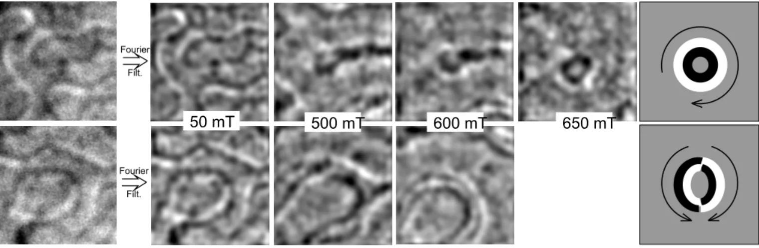
FIG. 1: Magnetization process on FePd thin film. The two rows present two different areas in the film. Both of them present a magnetic bubble state just before saturation. Left images are raw datas while the other images are enhanced by Fourier filtering. Right images are simple schemes to highlight the contrast observed in the last step of magnetization process. Arrows point out the direction of magnetic induction in bubbles. Images are 500 × 500 nm.
the magnetization process. We observe couples of black and white contrasts corresponding to the Bloch walls11.
These pictures have been obtained for increasing applied fields. We should notice that upon 500 mT the quality of the images decreases due to the action of the objective lens on the image formation. Nevertheless it is possible to follow the shape of the domains during the magneti-zation process (enhanced here by Fourier filtering). We observe in both cases that a magnetic domain collapses to a bubble state. Attention can thus be paid on the chirality of the Bloch wall. The chirality (sense of the magnetization inside the Bloch wall) is directly linked to the Fresnel contrast: the wall chirality of a black/white contrast and the chirality of a white/black contrast are opposite. Knowing this, the observation of the two mag-netic bubbles presented in the right images of Fig. 1 gives some information on the magnetization inside the domain walls of the bubbles. The first bubble presents a continu-ous domain wall, swirling all around the bubble, whereas the other one exhibits two different parts with the same magnetization orientation. In the latter configuration, the magnetization inside the domain wall experiences two rotations of 180◦ localized at the top and the bottom of
the bubble. These switching areas are known as vertical Bloch lines (VBL). One can notice the main difference in the two bubble shapes: the first one is almost round while the second bubble seems to be slightly elongated along the vertical direction.
To confirm the role of VBL on the bubble shape, we have thus simulated the inner structure of domain walls containing VBL.
III. SIMULATION OF DOMAIN WALLS WITH
VERTICAL BLOCH LINES
The numerical simulation of magnetic bubbles is not a tractable problem with standard codes. Indeed it re-quires to handle large systems whose size is related to the size of the bubbles, but with regions where the mag-netization varies rapidly in space, such as domain walls and all their substructures. Considering all regions with the same level of refinement is clearly not well adapted to such a multiscale problem and leads to a high computa-tional effort. The same level of accuracy can be reached with a coarser mesh in uniformly magnetized regions.
In this work we used a multiscale code (Mi µMagnet) based on an adaptive mesh refinement technique, as well as on a mixed atomistic-micromagnetic approach, to achieve both precision and computational efficiency14.
Given the large size of the systems we envisage here, the code was only used in its micromagnetic mode. It has been recently shown that micromagnetic calculations can be applied to singularities appearing in VBL, called Bloch Points (BP)15. In all calculations the mesh step is kept
lower than half the exchange length.
Parameters are chosen in agreement with experi-mental measurements16: the saturation magnetization,
anisotropy constant and exchange stiffness are Ms =
106 A.m−1, K = 106 J.m−3, and A = 7 × 10⁻¹² J.m−1.
With such parameters, the exchange length is lex =
p2A/(µ0Ms2) = 3.3 nm.
Two types of computations have been carried out. First we investigate the properties of a straight domain wall containing a VBL. Secondly we study the role of VBL on the shape of the magnetic bubbles in FePd lay-ers.
FIG. 2: Schematic representation of the system used to study the structure of VBL in domain walls.
FIG. 3: (Color online) Cross-section of the whole system ob-tained from a multiscale simulation (Bloch wall, with a verti-cal Bloch line containing a Bloch point). The orientation of the magnetization for the in-plane component is given by the arrows and the color wheel, and by the grayscale for the out of plane contribution (along z). The norm of the arrows is proportional to the in plane magnetization. The lateral size of the system is 110 nm × 110 nm.
For all the values of the thickness h that we envis-age, we consider configurations with and without a BP (Fig. 4 and 5). The configuration without a BP can be
FIG. 4: (Color online) Cross-section along the planes z = h, z = h/2 and z = 0 (from top to bottom) with a VBL containing a BP.
An interesting feature of the domain wall containing a VBL without a BP is the so-called buckling of the mag-netization near the line. This buckling was already de-scribed in garnets, where it was ade-scribed to the diminu-tion of the magnetic charges created by the variadiminu-tion of the magnetization in the direction orthogonal to the wall8(which we note x here). These charges are called π
charges or dipolar charges, in analogy with π orbitals, because positive charges are associated with negative charges.
Analytical models, based on the assumption Q ≫ 1, and two dimensional simulations, predict a much smaller value of the buckling8. Given our material parameters,
it would be less than 2 nm, whereas it is around 10 nm for all the thicknesses we have considered. Three dimen-sional simulations for Q = 7.7 and thick garnet layers (h ≈ 50 lex) also give a tiny buckling. In this case, a tilt
of the wall is observed in the x − z plane that provides a compensation for the charges associated with the varia-tion of the magnetizavaria-tion along y (called σ or monopolar
4
FIG. 5: (Color online) Cross-section along the planes z = h, z = h/2 and z = 0 (from top to bottom) with a VBL containing no BP. 10 12 14 16 18 20 22 Thickness h in nm 0.003 0.004 0.005 0.006 0.007 0.008 0.009 0.010 ∆ E / E BP no BP
FIG. 6: (Color online) Relative energy of a system with and without a BP in the VBL. The reference energy is given by the system containing a domain wall without a VBL. The decrease of the energy when a BP is present is mainly due to the dipolar term.
charges)18.
Such a deformation is not present in our simulations. As shown in Fig. 7 and 8, the compensation of the σ charges is achieved by the buckling itself. It can be noted that this buckling is due to the dipolar term, although a small decrease of the exchange energy is also observed in the presence of buckling. Indeed, we have represented in Fig. 7 the magnetic charges −∂mx/∂x (π charges),
−∂my/∂y (σ charges) and the total charges after a
trans-formation φ → −φ on the configuration of Fig. 5. The angle φ refers to the orientation of the magnetization in the plane of the layer. The configuration after the minimization of the energy is shown in Fig. 8. The de-formation of the domain wall has reversed, whereas the exchange energy was invariant under the transformation. This indicates that the deformation must be ascribed to the compensation of π and σ charges, which cannot re-ally be distinguished, given the moderate value of Q. In-cidentally, the name “σ charges” is not really adapted to our case given that positive charges are associated with negative charges along y.
y y x x x y z (a)
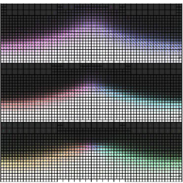
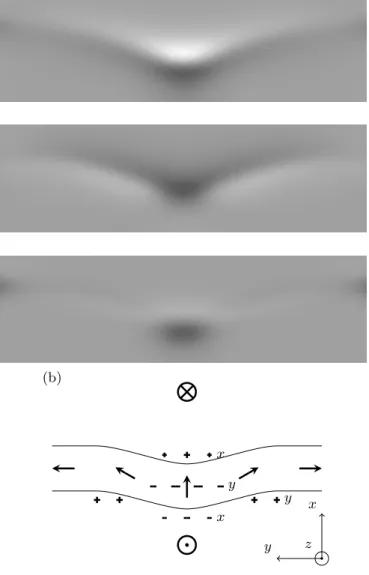
FIG. 7: Magnetic charges in the plane z = h/2 corresponding to the configuration of Fig. 5 when the transformation φ → −φ is performed on the magnetization and the configuration is left unrelaxed. From top to bottom: charges associated with the variation of mx, my and total charge. The charges
due to the variation along z are the same before and after the transformation and are not represented. Positive and negative charges are represented repectively by light and dark gray tones. On the schematic the letters x and y refer to charges due to the variation of mx and my.
exper-y y x x x y z (b)
FIG. 8: Magnetic charges in the plane z = h/2 after the relaxation of the configuration in Fig. 7.
imental datas on the straight wall. As seen in Fig. 1, at low fields the domain walls in this sample are not straight enough. On the contrary, is is possible to simulate entire bubbles and thus to reproduce the geometry of domain walls near saturation.
B. Magnetic bubbles
It seems reasonable to think that the deformation ob-served in straight domain walls can be responsible for the distorted shape of the magnetic bubbles. However, the curvature of the magnetic bubbles is such that the domain wall cannot be considered as a straight object. The presence of two VBL in a bubble, that bear opposite σ charges and thus attract themselves, may also affect the distortion. Therefore it is necessary to perform the simulation of entire magnetic bubbles.
The system considered in these simulations contains a magnetic bubble centered in a square of length 218 nm.
ble to stabilize the configuration with two VBL without a BP. As observed for straight domain walls, two BP nucle-ate because of the dipolar field. The bubbles with VBL containing BP are found to be almost circular (Fig. 9). The small distortion may be ascribed either to the in-teraction between the two VBL which possess opposite charges, or to a local stiffness due to the presence of the BP.
For a thickness of 15 nm, the configuration containing VBL with BP is not stable and the two BP migrate to-wards the two opposite surfaces of the system. The two regions that exbibit high spatial variations of the mag-netization (360◦ rotation for straight domain walls) are
thus located on opposite sides of the system (Fig. 10). This disappearance of the two BP is associated with a deformation of the domain wall, in agreement with the one found on straight domain walls in the previous sec-tion and with experimental results. Likewise the charges are minimized and the exchange energy decreases.
It is worth noting that the magnetization in the two lines is oriented in the same direction. This is called the winding configuration3. Lines with opposite orientations
of the magnetization constitute the unwinding configu-ration, and have found to be unstable: the two lines an-nihilate and the bubble is circular. Indeed, in order to minimize charges in both VBL the bubble would have a “heart”-like shape, which is not favorable. The orienta-tion in the two lines is close to the orientaorienta-tion in the rest of the domain wall at z = h/2.
A further step can be made towards the comparison between simulated and experimental configurations by simulating Fresnel contrasts that would be obtained from the multiscale calculations. They are given in Fig. 11. Beside the result corresponding to Fig. 10, we report the results for a bubble without a BP. It can be seen that the position of the contrast and the shape of the bubble agree fairly well.
Despite the good agreement on the shape of bubbles, the transition from the BP-free to the BP configuration does not occur at the same thickness experimentally and in the simulations. Indeed, the configurations without BP are not stable in our simulations for a thickness of 37.6 nm (and even 20.7 nm), whereas according to the deformation of the bubbles observed in the samples, VBL
6
FIG. 9: (Color online) Cross-sections of a system containing two VBL with a BP. From top left to bottom right: whole system at z = h/2 (lateral size 218 nm × 218 nm), zoom at z = h, z = h/2 and z = 0 (lateral size 90 nm × 90 nm). The system is 20.7 nm thick and a field of 0.3 T is applied. The largest cell lateral size is 27.3 nm, while the smallest is 1.7 nm.
FIG. 10: (Color online) Cross-sections of a system containing two VBL with no BP. From top left to bottom right: whole system at z = h/2 (lateral size 218 nm × 218 nm), zoom at z = h, z = h/2 and z = 0 (lateral size 90 nm × 90 nm). The system is 15 nm thick and a field of 0.25 T is applied.
FIG. 11: Comparison of simulated Fresnel contrasts and ex-perimental contrasts for the two type of bubbles observed. The defocalisation used is 100 µm.
contain a BP at this thickness. One reason for this dis-crepancy may be the presence of the soft layer on which the L10 layer is deposited. The exchange and
demag-netizing contributions to the energy are modified due to the different closure of the magnetic flux. The thickness of the bottom N´eel cap increases13, which induces a
dis-symmetry in the system and could favor the configuration without BP.
IV. CONCLUSION
Using Lorentz transmission electron microscopy on FePd samples and multiscale simulations, we have shown that it is possible to determine the magnetic structure of domain walls as thin as 8 nm. The presence of vertical Bloch lines in some bubbles has been demonstrated by microscopy. Bubbles containing two vertical Bloch lines exhibit a distortion of the classical circular shape. The simulation of entire bubbles has been possible thanks to the multiscale approach and has revealed that the de-formation observed experimentally is a signature of the absence of Bloch points inside the vertical Bloch lines. For straight domain walls in FePd, we predict a larger buckling than previously reported for other materials.
(1974), URL http://link.aip.org/link/?JAP/45/2705/ 1.
6
A. Hubert, AIP Conference Proceedings 18, 178 (1974), URL http://link.aip.org/link/?APC/18/178/1.
7
Y. Nakatani and N. Hayashi, Magnetics, IEEE Transac-tions on 24, 3039 (1988).
8
J. Miltat, A. Thiaville, and P. Trouilloud, Journal of Mag-netism and Magnetic Materials 82, 297 (1989).
9
J. Chapman, Journal of Physics D : Applied Physics 17, 623 (1984), lorentz.
10
P. Aitchison, J. Chapman, V. Gehanno, I. Weir, M. Sche-infein, S. McVitie, and A. Marty, Journal of Magnetism
T. Schrefl, Physical Review B 67, 094410 (2003).
16
V. Gehanno, A. Marty, B. Gilles, and Y. Samson, Physical Review B 55, 12552 (1997).
17
A. Hubert, Journal of Magnetism and Magnetic Materials 2, 25 (1976).
18
A. Thiaville, J. B. Youssef, Y. Nakatani, and J. Miltat, 35th annual conference on magnetism and magnetic mate-rials 69, 6090 (1991).
19
A. A. Thiele, Journal of Applied Physics 41, 1139 (1970), URL http://link.aip.org/link/?JAP/41/1139/1.