HAL Id: tel-03203250
https://hal.univ-lorraine.fr/tel-03203250
Submitted on 20 Apr 2021HAL is a multi-disciplinary open access archive for the deposit and dissemination of sci-entific research documents, whether they are pub-lished or not. The documents may come from teaching and research institutions in France or abroad, or from public or private research centers.
L’archive ouverte pluridisciplinaire HAL, est destinée au dépôt et à la diffusion de documents scientifiques de niveau recherche, publiés ou non, émanant des établissements d’enseignement et de recherche français ou étrangers, des laboratoires publics ou privés.
membranes for fuel cells
Mylène Robert
To cite this version:
Mylène Robert. Impact of degradation and aging on properties of PFSA membranes for fuel cells. Me-chanics of materials [physics.class-ph]. Université de Lorraine, 2021. English. �NNT : 2021LORR0004�. �tel-03203250�
AVERTISSEMENT
Ce document est le fruit d'un long travail approuvé par le jury de
soutenance et mis à disposition de l'ensemble de la
communauté universitaire élargie.
Il est soumis à la propriété intellectuelle de l'auteur. Ceci
implique une obligation de citation et de référencement lors de
l’utilisation de ce document.
D'autre part, toute contrefaçon, plagiat, reproduction illicite
encourt une poursuite pénale.
Contact : [email protected]
LIENS
Code de la Propriété Intellectuelle. articles L 122. 4
Code de la Propriété Intellectuelle. articles L 335.2- L 335.10
http://www.cfcopies.com/V2/leg/leg_droi.php
École Doctorale SIMPPÉ : Sciences et Ingénierie des Molécules, des Produits,
des Procédés et de l’Énergie
THÈSE
En vue de l’obtention du titre de
DOCTEUR DE L’UNIVERSITÉ DE LORRAINE
Mention « Énergie et Mécanique »
Impact of degradation and aging on properties of PFSA
membranes for fuel cells
Impact des dégradations et du vieillissement sur les propriétés
des membranes PFSA pour piles à combustible
Présentée par
Mylène Robert
Soutenue publiquement le 12 Janvier 2021
Composition du jury :
Rapporteurs : M. Vito Di Noto Professeur, Université de Padoue, ChemTech, Padoue (Italie)
Mme Cristina Iojoiu Directrice de recherche, CNRS, LEPMI, Grenoble
Examinateurs : Mme Corine Bas Professeur, Université Savoie Mont-Blanc, LMOPS, Le Bourget du lac
M. Bruno Ameduri Directeur de recherche, CNRS, ICGM, Montpellier Mme Assma El Kaddouri
(co-encadrante de thèse)
Maître de conférences, Université de Lorraine, LEMTA, Nancy
Encadrants : M. Olivier Lottin (directeur de thèse)
Professeur, Université de Lorraine, LEMTA, Nancy
M. Jean-Christophe Perrin (co-directeur de thèse)
Maître de conférences, Université de Lorraine, LEMTA, Nancy
Invité : M. Stéphane André Professeur, Université de Lorraine, LEMTA, Nancy
« Success is not the key to happiness. Happiness is the key to success. If you like what you are doing, you will be successful. »
Merci à vous
Me voilà arrivée au bout de cette aventure unique. Bien sûr tout n’a pas toujours été tout beau tout rose mais ce sont justement ces épreuves et leur franchissement qui font la richesse, la complexité et l’authenticité de ce travail de thèse. Beaucoup de personnes ont contribué à son aboutissement, mais également à me faire évoluer tant d’un point de vue professionnel que personnel, et je me dois donc de leur exprimer toute ma gratitude avant de clore ce manuscrit.
Je tiens tout d’abord à remercier les membres du jury pour avoir accepté d’évaluer mon travail. Merci aux rapporteurs, Vito Di Noto et Cristina Iojoiu, pour leurs commentaires très intéressants sur mon manuscrit, et à Bruno Ameduri pour son analyse fine et approfondie du manuscrit ainsi que pour sa gestion, en qualité de président du jury, d’une soutenance malheureusement organisée en visioconférence en ces temps difficiles. Merci à vous trois mais également à Corine Bas et Stéphane André pour les discussions enrichissantes, et ouvrant de nombreuses nouvelles pistes de réflexion sur ce travail de thèse, à l’issue de ma soutenance.
Tout ceci a été permis grâce à trois personnes fantastiques, trois encadrants de haut niveau se complétant à la perfection pour ce travail de thèse, qui ont su me guider et me donner envie de donner le meilleur de moi-même. Assma, Olivier et Jean-Christophe, il est difficile de trouver les mots justes pour vous exprimer une gratitude à la hauteur de tout ce que vous m’avez apporté pendant ces dernières années. Vous m’avez donné l’opportunité dès mon master de découvrir un domaine de recherche plus que passionnant, mais également de découvrir un laboratoire et une équipe au top offrant un cadre professionnel convivial et chaleureux dans lequel on ne peut que réussir. Je vous remercie tous les trois pour vos conseils, votre disponibilité, votre dévouement et votre ténacité au travail, votre aptitude à transmettre vos connaissances et vos savoir-faire avec pédagogie, sans oublier votre bonne humeur constante et votre bonne entente. On ne peut pas rêver mieux pour un encadrement de thèse :-)
Merci Assma pour ta force indéfectible, tes multiples conseils et tout le temps que tu as consacré pendant ces nombreuses discussions que l’on a pu avoir toutes les deux pour comprendre mes résultats. Ton dynamisme, ta patience et ta ténacité ont été pour moi une source d’inspiration pour traverser les diverses péripéties qu’apporte le travail de thèse.
Jean-Christophe, merci pour ton dynamisme, ta gentillesse et ta rigueur scientifique, pour les nombreux échanges que l’on a pu avoir. Bien évidemment, je te rendrai la pareille en te
transmettant ma capacité à organiser et classer les échantillons de membranes sans se mélanger les pinceaux ;-)
Merci à Olivier de m’avoir fait partager un peu de ta grande culture scientifique, d’avoir cru en moi pour mener à bien ce travail de thèse, d’avoir été disponible pour répondre à mes nombreuses interrogations et d’avoir scruté la moindre faute dans les différentes publications et dans mon manuscrit.
Merci à Pascal Boulet et tout le personnel administratif et technique qui travaillent durs pour assurer les très bonnes conditions de travail qui sont celles du LEMTA. Merci aux secrétaires pour leur travail irréprochable et les discussions matinales autour d’un bon thé chaud, merci à Franck pour son aide si précieuse à la gestion du labo de chimie, merci à Alain pour sa bienveillance et les petites discussions de couloir, merci à Hadrien pour m’avoir si gentiment accordé un accès si régulier aux spectros IR.
J’exprime également ma reconnaissance envers Fabrice Lemoine, directeur du laboratoire à ce moment-là, pour m’avoir donné la chance d’effectuer cette thèse au sein du LEMTA. Je remercie l’ensemble de l’équipe HSE (ou pile pour les intimes) pour les échanges et les discussions à droite et à gauche dans le dédale des couloirs du LEMTA ou lors de la pause-déjeuner : Julia et son leadership, Sophie et sa bonne humeur, Nicolas et ses petits-mots toujours gentil en passant devant le bureau, Feina et ses précieuses connaissances sur les membranes et les techniques de caractérisation, Gaël et son sourire constant, Jérôme et sa maîtrise inégalable des bancs d’essai, Sébastien et son aide inestimable quand il s’agit de résoudre un problème avec les spectros RMN. Un merci tout particulier à Kévin pour son implication dans mon travail de thèse, pour ses connaissances et sa méthodologie ; tu m’as été d’une aide et d’un soutien réels pour la réalisation de mes expériences et de mes mesures. Enfin, je souhaite le meilleur à la relève de l’équipe pile : Zarina, Feryal, Meriem, William, Rémi, Christine.
Un grand merci au bureau 016V, que ce soit avec les anciens occupants ou les nouveaux, la bonne ambiance, les fous-rires et les discussions à n’en plus finir sur des sujets divers et variés sont toujours de rigueur : merci Saïd pour avoir accueilli la petite nouvelle doctorante que j’étais, Milad pour m’avoir fait découvrir un petit bout de ta culture et Salah pour les nombreuses discussions que l’on a pu avoir ensemble. Toi et tes petites entourloupes pour avoir toujours plus de gâteaux fait maison, grrrr ! ^^ Tu es une belle personne et je n’ai aucun doute que tu vas réussir à clore ta thèse en beauté. Julian, mon cher co-bureau adoré ! Merci pour ton aide et ton oreille attentive, tu as toujours été là, que ce soit pour me remonter le moral lors de
mes coups de stress ou pour rigoler et passer de bons moments au bureau. Merci également à Meriem, la petite dernière arrivée, qui a très vite adopté l’attitude du bureau et avec qui il est toujours très plaisant de discuter et d’échanger à propos de tout.
Merci à tous les potos de promo du LEMTA pour les nombreuses discussions sur notre situation de doctorant, pour les déjeuner partagés ensemble au quatrième étage, au RDC ou dehors, pour les formations DCCE qui nous ont permis de nous découvrir : Romain et Mehdi (je me suis si souvent arrêté dans votre bureau pour refaire le monde !), Lucas, Axel, Anas (t’as vu finalement t’en a pas cassé tant que ça des pointes d’AFM !), Arthur, Alexandre, Shririn.
Merci également à tous les collègues du LEMTA avec qui j’ai aimé partager une bonne bière (ou autre breuvage) : Giuseppe, ou plutôt Peeeppe!, dont le large sourire n’a d’égal que sa générosité et sa joie de vivre, Mathilde, avec qui j’ai apprécié partager le labo de chimie mais également de bons petits gâteaux pour le goûter, Juan David, toujours le sourire et le petit mot pour faire rire, Ahmad, le savoureux mélange des culture française et libanaise, Arthur, dont le sourire éclatant et toujours plus grand ainsi que le rire bien caractéristique resteront gravé au LEMTA, Justine, ami RMNiste au caractère bien trempé qui la conduira loin dans les sciences, sans oublier Solange, ma petite pompière adoré dont le naturel avenant, généreux et optimiste en fait une personne merveilleuse et une amie inestimable.
Et puisque l’on termine toujours par le meilleur, j’exprime ma profonde gratitude à ma famille, à mes amis et plus particulièrement à mes parents. Je vous remercie tous les deux de nous avoir inculqué – à Pierre, Vincent et moi – de belles valeurs, de nous avoir élevé dans un environnement où partage, entraide, générosité et famille sont les maîtres-mots. Merci pour vos sacrifices, votre soutien inépuisable, votre présence dans les moments de joie comme dans la difficulté, qui ont largement contribué à faire de moi la personne que je suis aujourd’hui. On n’a pas l’habitude de le dire ou de le montrer dans la famille Robert mais je vous aime tant.
D’innombrables mercis également à mon cher et tendre Dr Olivier Carrivain, que j’ai eu la chance de rencontrer entre deux spectros IR en salle Carnot au LEMTA, et dont les précieux conseils et mots-doux font de moi une femme épanouie, heureuse et un petit peu moins anxieuse. Merci d’être là pour moi au quotidien, que ce soit pour partager les bonnes nouvelles ou pour m’aider à gérer mes multiples crises d’angoisse/remises en question, tu me pousses toujours à me dépasser, donner le meilleur de moi et je t’en suis extrêmement reconnaissante.
Table of contents
Résumé élargi
... xiiiPreamble
... 1Chapter I – State of the art of proton-exchange membrane fuel cell (PEMFC)
systems ...
51. Overview of PEMFC ... 7
1.1. Operating principle of PEMFC ... 7
1.2. Fuel cell components ... 10
2. Generalities on PFSA membranes ... 22
2.1. Chemical structure and morphology ... 22
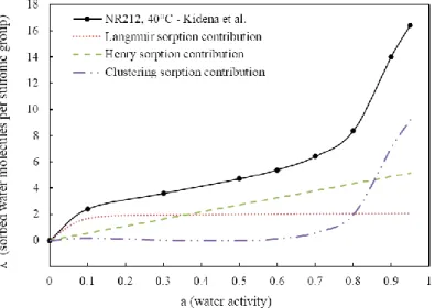
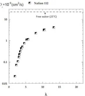
2.2. Sorption and transport of water and protons ... 25
2.3. Mechanical properties ... 32
3. Degradation mechanisms of membrane-electrode assemblies (MEA) ... 35
3.1. Gas diffusion media ... 35
3.2. Catalyst layers ... 35
3.3. PFSA membranes ... 44
Conjoint chemical and mechanical degradations ... 61
4. Objectives of the thesis work ... 63
Chapter II
– Experimental techniques ...
891. Chemical and electrochemical characterizations ... 90
1.1. Fluoride emissions measurement via ion-selective electrode (ISE) ... 90
1.2. ATR-FTIR spectroscopy ... 94
1.3. NMR spectroscopy ... 95
2. Characterization of membrane functional properties ... 99
2.1. Liquid-state 1H-NMR ... 99
2.2. Water uptake measurements ... 102
Chapter III – Accelerated chemical degradation of PFSA membranes: Fenton’s
reaction protocol
... 1071. State of the art: chemical degradation of PFSA membranes induced by Fenton’s
reaction ... 108
2. Description of the aging and cleaning protocols ... 111
2.1. Sample pretreatment ... 111
2.2. Aging protocol based on Fenton’s reaction and operating conditions ... 111
2.3. Cleaning of aged samples ... 113
3. Effect of Fenton’s reagent concentrations on the chemical degradation of PFSA membranes ... 114
3.1. Macroscopic morphology evolution of aged membranes ... 115
3.2. Fenton solutions analysis: quantification of the chemical degradation ... 117
4. Conclusions ... 119
Chapter IV – Time-resolved monitoring of PFSA membranes degradation induced
by Fenton’s reaction
... 1251. Introduction ... 126
2. Establishment of the time-resolved monitoring of ex-situ chemical degradation ... 126
3. Chemical structure evolution after exposure to Fenton’s reagents ... 127
3.1. ATR-FTIR spectroscopy ... 127
3.2. Solid-state 19F-NMR spectroscopy ... 129
4. Quantification of the chemical degradation ... 130
4.1. Weight loss and fluoride emissions ... 131
4.2. Liquid-state 19F NMR spectroscopy ... 132
4.3. Correlation between weight loss and emissions of degradation products ... 134
5. Impact of the degradation on PFSA membranes functional properties ... 135
5.1. Water sorption capacity in aged membranes ... 135
5.2. Water self-diffusion after chemical degradation ... 137
6. Discussions ... 138
6.1. Comparison of PFSA membrane degradation with literature ... 138
6.2. Contribution of reinforcement layer and radical scavengers against chemical degradation ... 140
7. Conclusions ... 143
Chapter V – Effects of conjoint chemical and mechanical stress on PFSA
membranes
... 1491. Introduction ... 150
2. Experimental device and protocols ... 151
2.1. Description of the aging device ... 151
2.2. Ex-situ coupled mechanical and chemical stress tests ... 153
2.3. Electrochemical tests in single cell ... 155
3. Characterization of membrane degradation ... 157
3.1. Preliminary tests ... 157
3.2. Cyclic compression stress ... 158
3.3. Influence of the mechanical strength ... 160
3.4. Impact of aging test duration ... 161
3.5. Impact of the presence of GDL ... 162
4. Impact of conjoint chemical and mechanical stress on the membrane structure and functional properties ... 164
4.1. Chemical structure evolution of membranes after conjoint chemical and mechanical stress ... 164
4.2. Evolution of water sorption and transport properties in aged membranes ... 165
4.3. Cell performances after conjoint mechanical and chemical stresses ... 167
5. Contribution of the mechanical stress on membrane properties: comparison with pure ex-situ chemical stress tests ... 172
6. Conclusions ... 176
Conclusions and Perspectives
... 183Appendix A – Optimization of the experimental protocols
... 189Appendix B – Impact of a static compressive stress on the functional properties of
PFSA membranes
... 199Résumé élargi
Contexte de l’étude
« La transition énergétique est une course contre la montre du changement climatique qui nous menace.»
Il y a trois ans, Nicolas Hulot, alors ministre de la Transition écologique et solidaire, promulguait ces mots pour présenter son "plan climat" visant à accélérer la transition énergétique et climatique de la France, mais aussi à assurer le respect des objectifs de la France fixés lors de la COP21. Plus particulièrement, deux des principaux objectifs de ce plan climat sont de porter la part des énergies renouvelables dans le mix énergétique à 32 % d'ici 2030 et d'atteindre une neutralité carbone d'ici 2050. Ces deux objectifs nécessiteront le bouleversement de notre société moderne et l'introduction de mesures drastiques pour réduire considérablement nos émissions de gaz à effet de serre (GES) d'origine anthropique.
Au cours des dernières décennies, la concentration de CO2 a atteint des valeurs sans
précédents depuis des centaines de millénaires. Selon l'Agence internationale de l'énergie (AIE), les émissions anthropiques de GES ont été multipliées par 145 en moins de 200 ans, entraînant une augmentation de la température mondiale moyenne d'environ 0,85 °C. Les effets du réchauffement climatique ne peuvent plus être ignorés puisqu’ils nous entourent au quotidien : multiplication des catastrophes naturelles et des vagues de chaleur, fonte des calottes glaciaires, élévation du niveau des mers, etc. Dans le contexte du réchauffement climatique actuel qui s'accélère un peu plus chaque année, la place de l'hydrogène comme vecteur énergétique dans le mix énergétique vert de demain ne fait plus aucun doute. Par exemple, le stockage et la distribution de l'hydrogène produit par l'électrolyse de l'eau seraient bénéfiques pour augmenter la part des énergies renouvelables dans le mix énergétique en compensant l'intermittence des ressources naturelles telles que l'énergie solaire ou éolienne. En France, le gouvernement a lancé – en septembre 2020 – son plan hydrogène vert avec un investissement de 7,2 milliards d'euros pour la prochaine décennie, visant à promouvoir le développement de l'électrolyse de l'eau et des véhicules à pile à combustible à hydrogène (bus, poids lourds, trains).
Le développement de la filière hydrogène et des énergies vertes repose en partie sur celui des piles à combustible à membrane échangeuse de protons (PEMFC en anglais), source d'énergie prometteuse et non polluante qui convertit directement une énergie chimique en une énergie électrique. La réaction électrochimique se produisant au cœur de la pile repose sur l’oxydation du dihydrogène à l’anode, générant des électrons et des protons transportés jusqu’à la cathode afin de permettre la réduction du dioxygène (Figure 1). Les électrons transitent par un circuit externe afin de générer la puissance électrique de la pile tandis que les protons sont transportées par une membrane polyélectrolyte ionomère, i.e. un copolymère thermoplastique possédant une faible proportion de groupements ioniques (≈ 1–10 % de motifs de répétition). D’un point de vue pratique, la pile à combustible est constituée de divers matériaux, ayant chacun un rôle bien spécifique dans le bon fonctionnement de la pile, qui sont empilés en série afin d’obtenir une puissance totale pouvant aller de quelques watts à plusieurs mégawatts.
Figure 1 – Représentation schématique du fonctionnement d’une pile à combustible (Adapté de la référence [1]
avec la permission de l’auteure).1
Les PEMFC présentent des avantages intéressants car elles offrent une alternative attrayante et efficace aux combustibles fossiles avec un large éventail d'applications possibles dans les domaines stationnaire, portable et des transports. Cependant, malgré les nombreux progrès technologiques réalisés au cours de ces dernières décennies, la commercialisation à grande échelle des PEMFC est encore limitée par des coûts de fabrication trop élevés ainsi que par des
1. El Kaddouri A. 2014 Mise en évidence de la dégradation du liant ionomère dans les électrodes de pile à combustible. Grenoble. See http://www.theses.fr/2014GRENI014.
problèmes de durabilité et de performance. De nombreuses études ont été menées ces dernières années afin de mieux comprendre les phénomènes de vieillissement et ceux-ci ont permis d’identifier la dégradation de la membrane polyélectrolyte comme l'un des principaux facteurs limitant la durée de vie des PEMFC [2–4]. Dans ces études, il a été clairement démontré que la membrane est exposée à des conditions difficiles lors du fonctionnement, impliquant d'importantes contraintes chimiques et mécaniques qui peuvent conduire à de graves dégradations de la structure et des propriétés de la membrane et, dans le pire des cas, à l'arrêt de la pile à combustible en raison de la défaillance de la membrane.2
Par ailleurs, le bon fonctionnement de la pile repose en partie sur la capacité de la membrane à acheminer les protons de l’anode vers la cathode. La conductivité protonique de la membrane dépend de la mobilité de l'eau dans sa structure, elle-même fortement liée à sa capacité de sorption d'eau. La gestion de l'eau dans la membrane est donc un paramètre essentiel pour optimiser les performances des piles à combustible et améliorer leur durabilité. Pour cette raison, il est nécessaire d’avoir de fortes connaissances sur les effets des dégradations mécaniques et chimiques sur la capacité de sorption et le transport de l'eau dans la membrane. De nos jours, les membranes d'acide perfluorosulfonique (PFSA en anglais) sont les matériaux les plus couramment utilisés dans les systèmes PEMFC, grâce à leur remarquable conductivité protonique et à leur stabilité chimico-mécanique, mais souffrent encore d'un taux de dégradation élevé pendant le fonctionnement de la pile [5]. Bien qu'il soit communément admis que les contraintes chimiques et mécaniques rencontrées lors du fonctionnement en pile interagissent les unes avec les autres, induisant une accélation de la dégradation globale des membranes, seules quelques recherches ont été consacrées à l'effet des contraintes combinées sur les membranes PFSA parmi d’innombrables études menées indépendamment sur chacune de ces contraintes. En conséquence, il est nécessaire de comprendre cette interaction synergique entre les dégradations mécaniques et chimiques ainsi que son impact sur la structure et les propriétés des membranes PFSA. Par ailleurs, malgré les différentes stratégies développées pour prolonger la durée de vie des membranes PFSA, telles que l’introduction d’un renfort
2. Borup R et al. 2007 Scientific aspects of polymer electrolyte fuel cell durability and degradation. Chem. Rev. 107, 3904– 3951. (doi:10.1021/cr050182l)
3. Dubau L et al. 2014 A review of PEM fuel cell durability: materials degradation, local heterogeneities of aging and possible mitigation strategies. Wiley Interdiscip. Rev. Energy Environ. 3, 540–560. (doi:10.1002/wene.113)
4. Zhao J, Li X. 2019 A review of polymer electrolyte membrane fuel cell durability for vehicular applications: Degradation modes and experimental techniques. Energy Conversion and Management 199, 112022. (doi:10.1016/j.enconman.2019.112022)
5. Zatoń M, Rozière J, Jones DJ. 2017 Current understanding of chemical degradation mechanisms of perfluorosulfonic acid membranes and their mitigation strategies: a review. Sustainable Energy Fuels 1, 409–438. (doi:10.1039/C7SE00038C)
mécanique ou de stabilisants chimiques, les membranes composites actuelles sont encore insuffisamment durables pour un fonctionnement à long terme des piles à combustible [6,7].3
Synthèse des résultats de l’étude
Les objectifs de ce travail de thèse sont d’apporter, grâce à des protocoles de vieillissement
ex-situ, de nouvelles connaissances sur l'effet de la combinaison des contraintes chimiques et
mécaniques sur la dégradation de la membrane PFSA – qu'elle soit renforcée ou non – ainsi qu'à caractériser et comprendre son impact sur les propriétés de la membrane et les performances en pile. Les mécanismes complexes de vieillissement associant les contraintes chimiques et mécaniques doivent donc être traités dans le cadre d'une approche multidisciplinaire. À cet égard, et grâce à une caractérisation multi-techniques, l'analyse de la structure chimique et des propriétés fonctionnelles des membranes PFSA avant et après les tests de vieillissement ont permis de corréler certaines propriétés physico-chimiques de la membrane à ses caractéristiques structurelles et ainsi de mettre en évidence plusieurs indicateurs de dégradation chimique.
Dans un premier temps, avant d'envisager une contrainte chimique et mécanique conjointe, il est nécessaire d’étudier l'impact d’une dégradation chimique pure ex-situ sur une membrane PFSA renforcée par rapport à une membrane non renforcée. La réaction de Fenton est un protocole de vieillissement ex-situ accéléré largement utilisé dans la littérature pour étudier la dégradation chimique des membranes PFSA qui permet de reproduire l'environnement fortement oxydant observé pendant le fonctionnement des piles à combustible. Il consiste ainsi à faire réagir du peroxyde d’hydrogène H2O2 avec des ions ferreux Fe2+ afin de générer les
radicaux hydroxyle HO• et hydroperoxyle HOO•. Cependant, un large éventail de combinaisons de concentrations en réactifs de Fenton peut être trouvé dans la littérature et semble avoir des effets différents sur les membranes PFSA, ce qui rend difficile la détermination de conditions – en terme de concentration en réactifs – de vieillissement ex-situ adéquat. À cet égard, une étude a été menée afin de clarifier l'influence des concentrations en réactifs de Fenton sur la dégradation chimique des membranes Nafion™ XL (renforcée) et NR211 (non renforcée).
6. De Moor G, Bas C, Charvin N, Dillet J, Maranzana G, Lottin O, Caque N, Rossinot E, Flandin L. 2016 Perfluorosulfonic acid membrane degradation in the hydrogen inlet region: A macroscopic approach. Int. J. Hydrog. Energy 41, 483–496. (doi:10.1016/j.ijhydene.2015.10.066)
7. Robert M, El Kaddouri A, Perrin J-C, Leclerc S, Lottin O. 2018 Towards a NMR-Based Method for Characterizing the Degradation of Nafion XL Membranes for PEMFC. J. Electrochem. Soc. 165, F3209–F3216. (doi:10.1149/2.0231806jes)
Nos résultats ont mis en évidence une forte dépendance de la dégradation des membranes aux concentrations de réactifs de Fenton, tant du point de vue chimique que morphologique. En effet, des concentrations élevées en H2O2 peuvent induirent des évolutions de la morphologie
des membranes PFSA – formation de cloques/bulles – qui n’ont jamais été rencontrés lors du fonctionnement en pile. Cette étude préliminaire a ainsi permis d'établir les conditions les plus appropriées requises pour induire une dégradation chimique efficace sans induire de changements morphologiques sévères.
Un suivi plus approfondi de la dégradation chimique ex-situ a ensuite été effectué afin d’étudier son impact sur la structure chimique et les propriétés de transport et de sorption de l'eau des membranes Nafion™ composite et conventionnelle : les membranes XL et NR211, respectivement.
Nos résultats ont démontré que les membranes XL et NR211 sont toutes deux chimiquement dégradées de manière significative par l'exposition à un environnement radicalaire puisque d’importantes pertes de poids et des concentrations élevées en ions fluorures ont été mesurées. Plus particulièrement, la RMN du fluor à l'état liquide a permis de mettre en évidence des émissions élevées de diacide perfluoro(3-oxapentane)-1-sulfonique-4-carboxylique – nommé ici Produit A pour plus de simplicité –, un composé fluoré dérivé de la chaîne latérale du PFSA qui a déjà été identifié dans la littérature comme l'un des principaux produits de dégradation du PFSA [8].4Toutefois, aucune évolution de la structure chimique ni aucun changement de la capacité d’échange ionique (CEI) n'ont été observés, ce qui implique que la dégradation des chaînes principales et latérales du PFSA se produit en proportions égales. Ce résultat indique que la décomposition du polymère se fait probablement par une réaction dite de « unzipping », entraînant ainsi la perte des chaînes latérales et la formation du produit A. De plus, la caractérisation des propriétés d’auto-diffusion et de sorption d'eau des membranes PFSA après 96 heures d'exposition aux réactifs de Fenton a mis en évidence que la dégradation chimique ne modifie pas ces propriétés de manière significative. Ces comportements sont très différents de ceux détectés dans une précédente étude après un fonctionnement de longue durée des piles à combustible, pour lesquelles une réduction de la capacité de sorption et de la mobilité de l'eau ont été observés [7]. Néamoins, des hétérogénéités de dégradation de la membrane, et plus généralement de l’assemblage membrane-électrodes, après un fonctionnement en pile ont déjà
8. Healy J, Hayden C, Xie T, Olson K, Waldo R, Brundage A, Gasteiger H, Abbott J. 2005 Aspects of the chemical degradation of PFSA ionomers used in PEM fuel cells. Fuel Cells 5, 302–308. (doi:10.1002/fuce.200400050)
été reportés dans la littérature [6,9].5Plus particulièrement, notre précédente étude a porté sur une région spécifique – d’entrée/sortie des gaz réactifs –, connue pour être soumise à de sévères conditions de fonctionnement (forte perméation à l’hydrogène, faible humidité des gaz) et par conséquent propice à d’importantes dégradations [7]. Ainsi, la différence observée dans ce travail de thèse pourrait suggérer que nos conditions ne sont pas suffisamment représentative de la dégradation sévère rencontrée dans la région d’entrée/sortie des gaz et que d’autres régions sujettes à une dégradation moins sévère pourraient avoir des comportements plus semblables. Par ailleurs, bien que la réaction de Fenton vise à accélérer la dégradation chimique des membranes PFSA, il ne peut être écarté que la durée du processus de dégradation (c'est-à-dire 96 heures contre plus de 12000 heures) ne soit pas assez longue pour observer les effets de la dégradation sur les propriétés fonctionnelles des membranes PFSA.
Figure 2 – Comparaison de l’évolution de la quantité de produit de dégradation entre une membrane Nafion™
XL renforcée et une membrane Nafion™ NR211 conventionnelle. Les courbes en traits pointillés se réfèrent à la quantité de produits de dégradation émis lorsque la part du renfort de PTFE de la XL n’est pas prise en compte
afin d’étudier la dégradation du PFSA seul.
La particularité de ce travail réside dans l'étude de la stabilité chimique de la membrane composite Nafion™ XL. À ce jour, les publications récentes ne se sont concentrées que sur la contribution de la couche de renfort ou sur l’impact de la dégradation chimique sur la durabilité mécaniques des membranes Nafion™ XL, mais aucune d’entre elles n’a étudié sa stabilité chimique. Nos résultats ont démontré que la dégradation chimique de la membrane XL est
9. Durst J et al. 2013 Degradation heterogeneities induced by repetitive start/stop events in proton exchange membrane fuel cell: Inlet vs. outlet and channel vs. land. Appl. Catal. B-Environ. 138, 416–426.(doi:10.1016/j.apcatb.2013.03.021)
inférieure à celle de la NR211 non renforcée, ce qui peut s'expliquer par la présence d'un renfort supplémentaire riche en PTFE, qui maintient l'intégrité mécanique de la membrane et évite ainsi une décomposition chimique supplémentaire, et/ou par la présence de piégeurs de radicaux à base de cérium qui peuvent atténuer les attaques radicalaires sur les chaînes de polymères (Figure 2).
Enfin, les effets de la contrainte mécanique et chimique combinée sur les membranes PFSA ont été étudiés, toujours par une approche ex-situ, avec un dispositif sur mesure (Figure 3). L'objectif de ce dispositif était de reproduire des conditions de vieillissement proches de celles rencontrées par la membrane lors du fonctionnement de la pile à combustible. De nombreux tests de vieillissement ont été réalisés afin de mieux comprendre l'influence des contraintes mécaniques, qu'elles soient statiques ou cycliques avec un niveau de pression négligeable ou élevé, sur la dégradation chimique des membranes Nafion™, et son impact sur leur structure chimique et leurs propriétés fonctionnelles.
Figure 3 – Représentations schématiques du dispositif de vieillissement couplant contraintes mécanique et
chimique et de la cellule de vieillissement.
Les résultats ont démontré que l'application d'une contrainte mécanique ne modifie pas les mécanismes de dégradation chimique puisque des produits de dégradation identiques à ceux identifiés dans le cas d'une contrainte chimique seule ont été détectés. Cependant, le comportement de la membrane XL face à la contrainte chimique semble légèrement différent puisque la combinaison d’une contrainte mécanique a conduit à l'apparition de bulles et de cloques près de la surface de la membrane. Par ailleurs, des taux d'émission de fluorure plus élevés ainsi que des courants de perméation d'hydrogène plus importants ont été obtenus avec
la NR211 plutôt qu'avec la XL dans la plupart des cas, ce qui pourrait s'expliquer par la meilleure résistance mécanique fournie par la couche de renfort supplémentaire présente dans la membrane XL. Cependant, cet avantage semble disparaître lorsque le niveau de pression est considérablement augmenté – de 5 à 10 MPa – puisque des taux de dégradation similaires ont été mesurés pour les membranes XL renforcée et NR211 non renforcée. De plus, bien qu'une décomposition significative du polymère ait été observée après des tests de contraintes combinées, ni les propriétés fonctionnelles telles que la capacité de sorption et d’auto-diffusion de l'eau, ni les performances de la membrane n'ont été significativement affectées. Comme dans le cas de la dégradation chimique seule, ces résultats peuvent également suggérer que la durée de dégradation mise en œuvre dans notre étude n'était pas assez longue pour induire des effets significatifs sur les propriétés fonctionnelles des membranes. Toutefois, il est important de noter que nos résultats se réfèrent à la dégradation globale de la membrane alors que les contraintes sont certainenement éprouvées différemment par la membrane sous les dents ou dans le canal. Il serait donc intéressant d’étudier de manière plus locale ces différentes zones.
D’autre part, les tests de vieillissement effectués avec des couches de diffusion des gaz (GDL en anglais) introduites entre la membrane et les plaques d'écoulement de la solution ont conduit à une diminution des émissions d’ions fluorures, suggérant que la GDL protège la membrane de cette dégradation conjointe. Néanmoins, il est possible que la présence de GDL entrave une bonne distribution et un renouvellement efficace de la solution à la surface de la membrane, ce qui aurait pour conséquence une dégradation moins importante. De plus, les nombreux dépôts de fibre de carbone observés à la surface des membranes ainsi que la chute de la tension en circuit ouvert et la hausse du courant de perméation mesurées tendent à montrer que l’utilisation de GDL dans les conditions de notre étude a un impact négatif et que sa dégradation sous l’effet de la compression pourrait conduire à de graves dommages irréversibles (i.e. perforations dues aux fibres de carbone cassées) de la membrane [10].6Il est donc difficile de conclure avec certitude sur l’effet protecteur de la GDL sur la dégradation conjointe des membranes PFSA.
Le développement de notre dispositif sur mesure et les tests de vieillissement accéléré associés constituent les éléments de base d’une meilleure compréhension des phénomènes de dégradation chimique et mécanique des membranes PFSA et ouvrent ainsi une grande variété de perspectives possibles.
10. Yi P, Peng L, Lai X, Ni J. 2011 A Numerical Model for Predicting Gas Diffusion Layer Failure in Proton Exchange Membrane Fuel Cells. J. Fuel Cell Sci. Technol 8. (doi:10.1115/1.4002312)
Preamble
« La transition énergétique est une course contre la montre du changement climatique qui nous menace. »
Three years ago, Nicolas Hulot, minister of Ecological and Solidarity Transition at that time, promulgated these words to introduce its “climate plan” aiming to accelerate the energy and climate transition of France, but also to ensure compliance with France’s objectives set at COP21. More especially, two of the main goals of this climate plan are to increase the part of renewables energies in the energy mix to 32 % by 2030 and to reach a carbon neutrality by 2050. These two objectives will require the disruption of our modern society and the introduction of drastic measures to considerably reduce our anthropogenic greenhouse gas (GHG) emissions.
Figure 4 – Evolution of some key indicators of the climate change for the last decades [1].1
1. Kennedy JJ, Kendon M, Killick RE, Dunn RJH, Allan RJ, Rayner NA, McCarthy M. 2020 Global and regional climate in 2019. Weather 75, 264–271. (doi:10.1002/wea.3822)
In recent decades, the concentration of CO2 indeed attained values that have never been seen
for hundreds of millennia. According to the International Energy Agency (IEA), anthropogenic GHG emissions were multiplied by 145 in less than 200 years, causing an increase of global average temperature of about 0.85 °C. The effects of global warming cannot be ignored anymore as they surround us on a daily basis: multiplication of natural disasters and heat waves, melting of the ice caps, rising sea levels, and so on…(Figure 4). In the context of today’s global warming accelerating a little more every year, the place of hydrogen as an energy vector in the green energy mix of tomorrow is no longer in doubt. For instance, the storage and distribution of hydrogen produced by the electrolysis of water would be valuable to increase the part of renewable energies into the energy mix by compensating the intermittency of natural resources such as solar or wind power. The French government launched in September 2020 its green hydrogen plan with an investment of 7.2 billion euros for the next decade aiming to promote the development of water electrolysis and of hydrogen fuel cell vehicles (buses, heavy-duty trucks, trains).
The development of the hydrogen industry and of green energies partly relies on that of Proton-Exchange Membrane Fuel Cells (PEMFC), promising zero-emission power sources which directly converts a chemical energy into an electrical energy. PEMFC bring interesting benefits since they offer an attractive and efficient alternative to fossil fuel with a wide range of possible applications in stationary, portable and transportation domains. However, in spite of numerous technological advances over these past decades, the large-scale commercialization of PEMFC is still impeded by too high manufacturing cost as well as durability and performance issues.
In recent years, countless studies have been carried out to provide a better understanding of aging phenomena. They identified the degradation of polyelectrolyte membrane as one of the main factor limiting the PEMFC lifetime. In these studies, it was clearly demonstrated that the membrane is exposed to harsh conditions entailing important chemical and mechanical stresses that may lead to severe degradations of membranes chemical structure and functional properties and, in worst cases, to the fuel cell shutdown due to the membrane failure. Moreover, the proton conductivity of the membrane depends on the water mobility into the membrane structure which is itself strongly related to the water sorption capacity. Water management within the membrane is thus a critical parameter to optimize fuel cell performances and improve their durability. For this reason, deep understandings of the effects of the mechanical and chemical degradations on the water transport and sorption properties of membranes are required. Nowadays,
perfluorosulfonic acid (PFSA) membranes are the most-commonly used materials in PEMFC systems, thanks to their remarkable proton conductivity and their chemical-mechanical stability, but they still suffer from high degradation rate during fuel cell operation. Although it is commonly admitted that chemical and mechanical stresses occurring during fuel cell operation interact with each other to accelerate the global membrane degradation, this assertion may not be clearly evidenced so far and, in any case, a clear understanding of these interactions and their impact on the structure and the properties of PFSA membranes is required.
In this context, this thesis work has the double ambition to:
• Bring some key understandings on – simultaneous – chemical and mechanical degradation mechanisms of PFSA membranes during fuel cell operation,
• Characterize and understand the impact of these chemical and mechanical degradations on the water sorption and transport properties of PFSA membranes as well as on their fuel cell performances.
At the end of this thesis work, new insights will be provided on the coupling of mechanical and chemical stresses as well as the evolution of chemical structure, functional properties and cell performances of the PFSA membranes.
Chapter I
State of the art of proton-exchange membrane fuel cell
(PEMFC) systems
Table of
contents
1. Overview of PEMFC ... 7
1.1. Operating principle of PEMFC ... 7 1.2. Fuel cell components ... 10 Bipolar plates (BPP) ... 11 Gas diffusion layers (GDL) ... 12 Electrodes or catalyst layers (CL) ... 14 Membrane ... 17 2. Generalities on PFSA membranes ... 22
2.1. Chemical structure and morphology ... 22 2.2. Sorption and transport of water and protons ... 25 Water sorption ... 25 Water diffusion ... 28 Proton transport ... 30 2.3. Mechanical properties ... 32 3. Degradation mechanisms of membrane-electrode assemblies (MEA) ... 35
3.1. Gas diffusion media ... 35 3.2. Catalyst layers ... 35 Degradation mechanisms of the catalyst ... 36 Degradation mechanisms of the carbon-based support ... 40 Degradation mechanisms of the ionomer binder ... 41 3.3. PFSA membranes ... 44 Mechanical degradation ... 46 Chemical degradation ... 47 3.3.2.1. Formation of hydrogen peroxide and reactive oxygen species (ROS) ... 48 3.3.2.2. Chemical changes observed after in-situ experiments ... 50 3.3.2.3. PFSA membrane degradation through ex-situ aging protocols ... 53 3.3.2.4. Chemical degradation mechanisms ... 56
3.3.2.5. Mitigation strategies ... 59 Conjoint chemical and mechanical degradations ... 61 4. Objectives of the thesis work ... 63
This first chapter aims at providing an overview of the literature on PEMFC systems and more particularly on the electrolyte perfluorosulfonic acid (PFSA) membranes, key elements of PEM fuel cells, in order to define the context of this thesis work. A good knowledge of the place and role of PFSA membranes in the operation of PEMFC as well as of their morphology and functional properties are thus required to better understand the membrane degradation mechanisms occurring during fuel cell operation.
In that purpose, this literature review will be divided into three main parts:
➢ First section is dedicated to a brief description of PEMFC operating principle and a deeper description of PEMFC components,
➢ Second section is focused on the main functional properties of Nafion™ membranes in
relation with the morphology of the polymer,
➢ Finally, the last section will describe the principle degradation mechanisms of membranes-electrode assemblies (MEA) with an emphasis on those of PFSA membranes.
1. Overview of PEMFC
1.1.Operating principle of PEMFC
PEMFC (for Proton Exchange Membrane Fuel Cells or Polymer Electrolyte Membrane Fuel Cells) are electrochemical devices that allow the direct conversion of chemical energy into electrical power. They are composed of a solid polyelectrolyte, an ionomer membrane, sandwiched between two porous electrodes where electrochemical reactions take place. The operating principle of PEMFC and the associated electrochemical reactions are illustrated on Figure 1.1. A gaseous flux of hydrogen is supplied to the anode side while the cathode side is fed with air or pure oxygen. At the anode side, the hydrogen is decomposed into protons and electrons according to the following half-reaction (hydrogen oxidation reaction, HOR):
H2 (g) → 2H++ 2e− EH+/H2
0 = O V
SHE Eq. 1.1
where 𝐸 is the standard cell voltage by reference to the SHE (Standard Hydrogen Electrode). Protons are carried to the cathode through the membrane while the electrons are collected by an external circuit, generating an electrical current. The electrons recombine with protons at the cathode side to reduce the oxygen and produce water according to the following half-reaction (oxygen reduction half-reaction, ORR):
𝑂2 (𝑔)+ 4𝐻++ 4𝑒−→ 2𝐻2𝑂(𝑙) 𝐸𝑂2/𝐻2𝑂
0 = 1.23 𝑉
𝑆𝐻𝐸 Eq. 1.2
The global reaction of the fuel cell between hydrogen and oxygen generates heat and electrical energy with liquid water as the only by-product:
Figure 1.1 - Schematic representation of the PEMFC operating principle (Adapted with permission from ref. [1]) At the equilibrium and under normal conditions of temperature and pressure, the ideal fuel cell voltage is given by the Nernst equation:
𝐸 = 𝐸0−𝑅𝑇 2𝐹𝑙𝑛 [ 𝑎𝐻2𝑂 𝑎𝐻2× (𝑎𝑂2) 1 2 ] = 𝐸0−𝑅𝑇 2𝐹𝑙𝑛 [ 1 𝑃𝐻2 × (𝑃𝑂2) 1 2 ] Eq. 1.4
where 𝐸0 is the standard cell voltage, 𝑅 is the gas constant, 𝑇 the temperature, 𝐹 the Faraday
constant equal to 96,845 C.mol-1 and 𝑎𝑖 the activity of each species. As the operating temperature of a PEMFC is generally below 100 °C, the water activity is usually assumed equal to 1 because liquid and vapor phases are at equilibrium. H2 and O2 are generally considered as
ideal gases so that their activity can be expressed as a function of their partial pressure 𝑃𝑖. The Nernst equation describes the difference between the electrode potential of the O2/H2O
redox couple at the cathode and the electrode potential of the H+/H2 redox couple at the anode
and gives an ideal fuel cell voltage of 1.23 Volts at room temperature.
The fuel cell theoretical efficiency, which corresponds to the ratio between the effective electrical power and the total energy released by the reaction, is about 83 % based on the higher heating value (HHV) of hydrogen and about 95 % by considering the hydrogen’s lower heating value (LHV). The difference between the higher and the lower heating values corresponds to the heat of water vaporization. The fuel cell efficiency is therefore different if the produced water is in the liquid form (HHV) or in the vapor form (LHV). Nevertheless, during operation the fuel cell efficiency is much lower because of several losses and the actual voltage deviates from the ideal voltage due to various polarization phenomena:
• Activation polarizations (𝜂𝑎𝑐𝑡), concerning the charge transfer at the membrane-electrode interface,
• Ohmic polarizations (𝜂𝑜ℎ𝑚), resulting from the electrical resistivity of fuel cell components and mainly that of the membrane, as well as the interface resistances between these components.
• Concentration polarizations (𝜂𝑐𝑜𝑛𝑐), depending on the electrolyte concentration around the electrodes.
Fuel cells are primarily characterized by their polarization curve, i.e. voltage vs. current density (in A/cm²) or current (in A) curve. The Figure 1.2 represents a typical polarization curve and shows that these polarization phenomena entail a significant decrease of the fuel cell voltage.
Figure 1.2 - Typical fuel cell polarization curve.
The activation polarization 𝜂𝑎𝑐𝑡 is due to the activation energy of the electrochemical
reactions taking place at the electrodes. Indeed, an activation energy is required to initiate the reactions and overcome the energy barrier. The kinetics of the HOR (Eq. 1.1) being slower than that of the ORR (Eq. 1.2), this voltage loss is mainly governed by the ORR.
In the intermediate range of current density, the ohmic loss 𝜂𝑜ℎ𝑚 is due to the electrical
resistivity of the components and more particularly the protonic resistance of the membrane. The voltage drop is linearly dependent on the current density and can be determined using Ohm’s law:
where 𝑖 is the current density and 𝑅 the total ohmic resistance of the components. However, it must be kept in mind that the total resistance of the cell can be strongly dependent on the operating conditions. In all cases, resistive losses can be minimized by reducing the thickness of the membrane or by improving its transport properties (ionic conductivity).
In the region of high current densities, the fuel cell voltage rapidly decreases since the transfer rate of reactant gases increases more slowly than the reaction rate. The reactant gases are progressively consumed when diffusing through the electrode and a concentration gradient is thus observed from one electrode to the other. This transport process depends on several parameters such as pressure, temperature, reactant concentration, electrode porosity, etc. The transport losses are mainly due to convective or diffusive phenomena and conduct to the decrease of the fuel cell voltage and reaction rate. The voltage variation induced by the concentration gradient is called concentration polarization ηconc and can be established from the
Nernst equation to describe the voltage loss, and by the Butler-Volmer equation to describe the reaction rate reduction. In both cases, the general equation can be expressed as follows:
𝜂𝑐𝑜𝑛𝑐 =𝑅𝑇
2𝐹ln (1 − 𝑖
𝑖𝑙) Eq. 1.6
with 𝑖𝑙 the limiting current density. Furthermore, the oxygen contribution is predominant for
voltage losses induced by concentration gradient since it diffuses more slowly than hydrogen. The concentration polarization can be minimized by optimizing the reactants distribution at the surface of the electrodes or the properties of the electrode (porosity, structure) in addition to the optimization of the operating conditions (P, T).
Consequently, the actual voltage of the fuel cell is calculated by subtracting the contribution of each polarization phenomenon to the theoretical value given by the Nernst equation (Eq. 1.4):
𝐸 = 𝐸0− (𝜂𝑎𝑐𝑡− 𝜂𝑜ℎ𝑚 − 𝜂𝑐𝑜𝑛𝑐) Eq. 1.7
In practice, the theoretical open-circuit voltage is not reachable, due to parasitic reactions as well as the low gas permeability of the membrane, and the actual open-circuit voltage of a PEMFC is approximately 1.0 V. For instance, the oxidation of platinum (Pt) particles, contained in the electrodes, occurs at a voltage above 0.75 V and significantly limits the open-circuit voltage.
The power generated by the PEMFC covers the range from ~1 watt to several megawatts, depending on the active surface and the number of elementary cells that can be stacked together. The actual elementary cell voltage being in the range from 0.6 V to 0.95 V, the elementary cells are connected in series to obtain the desired voltage. Each of them consists in two bipolar plates between which are comprised two gas diffusion layers (GDL) coated on the electrode side with a microporous layer (MPL), the electrodes and the membrane. The so-called membrane-electrode assembly (MEA) stands in general for the membrane and the two membrane-electrodes, as well as the two GDL with MPL. Each component has a specific role to play in the mechanical stability of the stack, the gas distribution or the electrical (ionic and/or electronic) conduction.
Bipolar plates (BPP)
The bipolar plates (BPP) have to fulfill various functions to ensure the optimum operation of the fuel cell. They are engraved with channels (around 0.5 to 1 mm in width and height) to provide the homogeneous distribution of the reactant gases on the whole active surface of the electrodes and to facilitate the management of water and heat produced during the reaction as well as the evacuation of excess gases. Moreover, BPP ensure the separation of individual cells and a good mechanical strength in the stack [2].
Over the past decades, many different materials have been investigated for manufacturing the bipolar plates. They can be divided into three groups: graphite, metallic and composite bipolar plates [2–4]. Graphite BPP present good chemical resistance and electrical conductivity but a poor mechanical strength and a high cost while metallic BPP have a great mechanical strength and good thermal and electrical conductivities, but poor chemical stability. However, fuel cell systems require great mechanical strength but also good chemical stability since corrosion issues can be generated by the acidic environment (pH = 2-3) and the temperature (80 °C) of the fuel cell [5]. Carbon-polymer composite BPP were developed to that purpose. However, their mechanical strength can be limited and they suffer from a low electrical conductivity [2].
Bipolar plates are also characterized by different flow-field configurations, elaborated for the optimization of the fuel cell operation [4,6]. Among these configurations, the most commonly used are parallel, interdigitated, and serpentine flow-field designs (Figure 1.3). More particularly, serpentine flow-field design have long been considered as giving the best performances [7,8].
Figure 1.3 - Example of flow-field design: (a) single serpentine channels, (b) parallel channels and (c)
interdigitated channels [9].
Gas diffusion layers (GDL)
Gas diffusion layers (GDL) are composed of a porous carbon mesh, with a thickness of 100 to 300 µm at the top of which is deposited a hydrophobic agent (typically based on polytetrafluoroethylene or PTFE)) in order to facilitate water management and thus avoid electrode flooding during operation [10]. They have multiple functions and properties [11,12]:
• Gas permeability, to supply reactant gases from the flow-field channels of bipolar plates to the electrodes,
• Water permeability, to evacuate the water produced during the reaction at the electrodes to the flow-field channels,
• Electrical and thermal conductivity, to evacuate electrons and heat to the flow-field channels,
• Mechanical strength, to provide mechanical support to the MEA.
Two kinds of porous supports based on carbon fibers have been used to manufacture GDL: carbon papers or carbon cloths (Figure 1.4) [13]. The porosity of such materials is high (around 80 %) and the pore size can vary from 10 to 30 µm within one GDL. This porous nature ensures a homogeneous distribution of reactant gases to the electrodes and facilitates water management.
Figure 1.4 - Micrographs from Scanning Electron Microscope (SEM) of (a) carbon paper and (b) carbon cloth
[13].
Furthermore, the high tortuosity of carbon paper induces important mass transport limitations under wet conditions but also permits to retain a more significant quantity of water, thus improving the membrane hydration, under dry conditions [13]. Consequently, the carbon paper is still an interesting alternative thanks to its low cost and because the deposit of the MPL at its surface is facilitated [14].
As mentioned earlier, water and reactant gases management of GDL is facilitated by the addition of a hydrophobic agent. More precisely carbon fibers are impregnated with PTFE (5 to 35 wt.%). It has been demonstrated that better performances were obtained at high and low current densities for an optimal PTFE loading of about 20 wt.% [15–17]. However, this optimal rate probably depends on the operating conditions. If the loading is too high, the PTFE will fill the pores of the GDLs and thus isolate the carbon fibers from each other, leading to an alteration of the GDL properties and, more particularly, to an increase of ohmic and water transport resistances [10,16–18].
In addition to this hydrophobic treatment, a thin microporous layer, less than 50 µm thick, is deposited on the surface of the GDL at the electrode side in order to improve the cell performances [19–21]. The MPLs are composed of carbon black and PTFE with a pore size smaller than that of GDL (0.01 to 15 µm vs. 10 to 30 µm). MPLs differ from the GDLs in their more dense and granular structure (Figure 1.5) [14]. They improve water and gases management by creating a porosity gradient and enhance the electrical contact between the GDL and the electrodes [22–24].
Figure 1.5 - SEM micrographs of GDL (a) with MPL and (b) without MPL [14].
In the case of MPL, an optimal PTFE loading of 20-35 wt.% enhances fuel cell performances, mainly for high current densities (> 0.5 A.cm-2) [14,16,25]. If the PTFE loading
is too high, or if the MPL is too thick (> 90 µm [14]), the gas permeability and the electron conductivity decrease, which limits the fuel cell voltage [14,16,25].
Electrodes or catalyst layers (CL)
The electrodes or catalyst layers are thin materials (8 to 15 µm) placed between the gas-diffusion layers and the membrane where the electrochemical reactions occur: oxidation on the anode side and reduction on the cathode side. For optimal fuel cell operation, the electrodes must meet several criteria: be porous to ensure the gas distribution to the reaction sites, facilitate the evacuation of excess reactants gases as well as by-products, have good electronic and proton conductivities but also support the deposited catalyst.
They are porous composite materials with a wide diversity of composition and manufacturing process [26]. They are made from a carbon-based support with dispersed catalyst particles to which is added a ionomer solution as a binder and an ionic conductor medium, with the same chemical composition than the membrane.
Despite a large variety of electrodes, two main categories can be distinguished: PTFE-bound [27,28] and thin-film electrodes [29,30]. The PTFE-bound electrode consists in creating a suspension by mixing together a Pt/C powder and a PTFE emulsion which is deposited on the GDL. Once the electrode is dry, GDLs are impregnated with a Nafion™ solution by brushing or spraying. The thin-film electrode is made from an ink that is based on an ionomer solution (the most commonly used is the Nafion™) in which Pt/C powder is added. This manufacturing process is nowadays the most commonly used since it leads to a more uniform distribution of polymer in the electrode and thus increases the electrode active area [28–31].
The most common catalyst is platinum (Pt) thanks to its low activation energy. The electrodes are generally composed of Pt nanoparticles dispersed on a carbon support to maximize its specific surface area. In order to increase the catalyst efficiency and thus decrease the loading, various carbon-based supports [32,33] and manufacturing processes (spraying, impregnation, etc.) [34–36] were investigated. For instance, the elaboration of supports from carbon aerogels [36] or the impregnation of carbon nanofibers with platinum aggregates by plasma spraying were studied [37,38]. On the other hand, the carbon black powder is extensively used for commercial MEAs manufacturing and for numerous investigations since it has the benefit of being widely available and cheap as well as having a high electronic conductivity. Although it is the most commonly used support, some of its main drawbacks, such as the presence of a micro-porosity in the carbon aggregates which can lead to Pt particles or Nafion™ capture [32,39], conduct to the research of new alternatives. Progress have been made to develop new carbon-based supports from mesoporous carbon. They demonstrate better mass transport properties thanks to a controlled porosity and a high specific surface area but they are also more prone to the corrosion [40]. Carbon nanotubes, carbon nanofibers and graphene, which present an enhanced durability and a higher specific surface area, have also been investigated but they remain expensive alternatives for an industrial use [41]. Furthermore, non-carbonaceous materials, such as metal oxide nanostructures based on titanium, indium, silica, or tungsten as well as conducting polymers, have been widely investigated to deal with the carbon corrosion issue (see § 3.2.2) [32].
Furthermore, the electrochemical reactions occur in a specific area named “triple phase boundary” where the electronic conductor (i.e. the carbon-based support), the catalyst (i.e. the Pt particles) and the protonic conductor (i.e. the ionomer binder) are simultaneously present (Figure 1.6). The exact mechanisms occurring at the triple phase boundary are not yet fully understood and its characterization is still difficult to implement [42]. However, it is important to note that this specific area is a useful but not realistic representation of reaction mechanisms since it would entail in practice the presence of infinite gaseous flux whereas its surface is necessarily zero.
Figure 1.6 - Schematic representation of the triple phase boundary at the anode side. PEM = proton exchange
membrane, CL = catalyst layer, GDL = gas diffusion layer PEMFC (Adapted with permission from ref. [1]).
In the case of PEMFC, the strong sensitivity of platinum to carbon monoxide contaminant (100 ppm at 80 °C) is a critical issue when hydrogen is obtained by steam reforming of hydrocarbons [43]. To overcome this issue, two methods have been developed. In the one hand, the CO content can be decreased below to 10 ppm after fuel reforming [44,45] thanks to a process called selective oxidation while, on the other hand, binary alloys (Pt/Co, Pt/Ru, Pt/Ni, Pt/Mn) or tertiary alloys (Pt/Ru/Mo, Pt/Ru/Co, Pt/Ru/Cr) can be used instead [46–48]. Nevertheless, these alloys still suffer from a lack of stability during fuel cell operation, causing the disappearance of one of the elements and the formation of hollow particles [49].
The ionomer present in the electrodes is a thermoplastic co-polymer characterized by its low concentration of ionic groups (< 15 mol.% of the repeating units). Its roles are to bind the catalyst to the membrane and to facilitate the proton transport through the electrodes (from the anode side to the membrane and from the membrane to the cathode side). The addition of an ionomer phase increases the dispersion of the catalyst and provides better mechanical strength to the electrode. The most commonly used ionomer in the PEMFC are long side chain (LSC) perfluorosulfonic acid (PFSA), commercialized under the name Nafion™ [46]. Moreover, other ionomers based on PFSA have been developed in order to improve cell performances; for example, Solvay Solexis S.A. elaborated PFSA with short side chains named Aquivion® [50,51]. This kind of ionomer provides better performances than LSC-PFSA for high current densities (> 1 A.cm-2) in high-humidity conditions and low temperature (60-80 °C). This enhancement is even better for low current densities (< 0.5 A.cm-2) when the fuel cell operates at high temperature (90-110 °C) in low-humidity conditions. Alternatives to PFSA-based ionomers such as sulfonated polyetheretherketone (s-PEEK) [52–54], sulfonated hydrocarbons [55] and other sulfonated polymers [32] are also currently studied.
In addition to the ionomer, a hydrophobic agent based on PTFE can be added [15,46]. It has been demonstrated that the presence of PTFE improves the cell performances and the power density, regardless of the humidity level [56,57]. Nevertheless, the presence of PTFE is not essential since good performances can be obtained with PTFE-free electrodes thanks to the presence of the MPL (see § 1.2.2).
Finally, a high ionomer loading can negatively affect the cell performances by decreasing the gas permeability, the proton (effective or apparent) conductivity and the access of reactants to the catalyst by clogging the pores of the electrode [58,59]. Some studies were performed to determine the optimal loading and it is now established that the best cell performances are obtained for a loading of about 25 to 35 wt.% [60–62].
Membrane
Likewise the ionomer binder comprised in the electrodes, the membrane is a thermoplastic ionomer with hydrophilic ionic groups. It is present in the form of a thin film and it must fulfill several essential functions for the correct operation of the fuel cell:
• Proton conductor: high proton conductivity (~100 mS.cm-1) guarantees the proton
migration from the anode to the cathode while limiting thermal losses.
• Electrical insulator: the membrane isolates the cathode from the anode to avoid short circuits.
• Gas impermeability: good barrier properties limit yield losses due to the diffusion of reactant gases and prevent gas crossover, a factor that leads to thermal and chemical degradations.
• Mechanical and chemical stability: the membrane must resist mechanical stress, caused by the operating conditions of the fuel cell, and chemical attacks from the formation of reactive oxygen species (ROS).
Nowadays, PFSA ionomers are the most commonly used membrane materials in PEMFC systems. They are composed of a hydrophobic PTFE backbone and perfluorinated side chains ended by hydrophilic sulfonic groups (-SO3-H+). The microstructure is organized in two phases:
the first is rich in polymer chains and confers to the membrane its mechanical strength and its relatively good chemical inertness to prevent chemical degradation in the oxidizing environment of the PEMFC. The second phase is rich in ionic sites, which promotes the sorption of water and the presence of continuous conduction path to enable the efficient transport of the
protons though the membrane. A deeper description of the chemical nature and properties of PFSA membranes will be developed in § 2.
Ionomer membranes are usually classified by their thickness (15 to 250 µm) and their equivalent weight (𝐸𝑊). The EW corresponds to the mass of dry polymer needed to neutralize an equivalent of base. It is directly linked to the ion exchange capacity (𝐼𝐸𝐶) expressed in milliequivalents per gram of dry polymer by the following relation:
𝐸𝑊 (𝑔. 𝑒𝑞−1) =1000
𝐼𝐸𝐶 Eq. 1.8
Over the past decades, multitudinous researches have been carried out on PFSA membranes in order to improve their mechanical strength, increase their conductivity, lengthen their lifetime while reducing their cost and thus extend their large-scale commercialization. In that respect, plenty of commercial PFSA membranes have been developed in the industry for the use in PEMFC and can be henceforth distinguished into several categories [63], among which:
- Non-reinforced long side chain (LSC) or short side chain (SSC) PFSA membranes [64,65].
- Reinforced PFSA membranes with a microporous support based on PTFE [64,65]. - Multi-Acid Side Chain (MASC) membranes based on Perfluoro Imide Acid (PFIA) or
modified-PFIA [66–68].
- Copolymer membranes based on vinylidene fluoride (VDF) and hexafluoropropene (HFP) [69,70].
- Chemically cross-linked membranes [71].
- Organic-inorganic nanocomposite membranes, which are modified-PFSA membranes containing nanoparticles of inorganic materials, metals or metal oxides such as SiO2,
TiO2, ZrO2, SnO2 [72–74].
However, the upper conductivity limit of current PFSA membranes being practically reached, it is now necessary to develop new perfluorinated materials with innovative structural attributes while maintaining the good properties of traditional PFSA membranes [72]. However, the upper conductivity limit of current PFSA membranes being practically reached, it is now necessary to develop new perfluorinated materials with innovative structural attributes while maintaining the good properties of traditional PFSA membranes [75]. In that respect, PFIA membranes seem to be promising candidates despite their chemical stability issue. Moreover, the glass transition temperature of PFSA membranes being around 90 to 125 °C [76,77], their

![Figure 4 – Evolution of some key indicators of the climate change for the last decades [1]](https://thumb-eu.123doks.com/thumbv2/123doknet/14543714.725198/23.892.167.743.518.1014/figure-evolution-key-indicators-climate-change-decades.webp)
![Figure 1.11 - Model of cylindrical polymeric aggregates proposed by Rubatat et al. [105,106]](https://thumb-eu.123doks.com/thumbv2/123doknet/14543714.725198/46.892.174.720.781.1028/figure-model-cylindrical-polymeric-aggregates-proposed-rubatat-et.webp)


![Figure 1.23 - X-ray diffractogram of pristine MEA and 1397h aged MEA before and after removing electrodes [203]](https://thumb-eu.123doks.com/thumbv2/123doknet/14543714.725198/64.892.265.631.468.747/figure-diffractogram-pristine-mea-aged-mea-removing-electrodes.webp)
![Figure 1.29 – COOH concentration profile in the cross-section of membrane degraded under OCV conditions thanks to electron probe microanalyzer (EPMA) and FTIR analyses [257]](https://thumb-eu.123doks.com/thumbv2/123doknet/14543714.725198/74.892.313.585.116.440/figure-concentration-membrane-degraded-conditions-electron-microanalyzer-analyses.webp)
![Figure 1.30 – Influence of the presence of Pt band in the membrane on (a) fuel cell performances and (b) fluoride emission during in-situ AST [195]](https://thumb-eu.123doks.com/thumbv2/123doknet/14543714.725198/75.892.189.691.217.399/figure-influence-presence-band-membrane-performances-fluoride-emission.webp)
