HAL Id: tel-01202344
https://tel.archives-ouvertes.fr/tel-01202344
Submitted on 20 Sep 2015
HAL is a multi-disciplinary open access
archive for the deposit and dissemination of sci-entific research documents, whether they are pub-lished or not. The documents may come from teaching and research institutions in France or
L’archive ouverte pluridisciplinaire HAL, est destinée au dépôt et à la diffusion de documents scientifiques de niveau recherche, publiés ou non, émanant des établissements d’enseignement et de recherche français ou étrangers, des laboratoires
Reconfigurable antennas for mobile phone and WSN
applications
Le-Huy Trinh
To cite this version:
Le-Huy Trinh. Reconfigurable antennas for mobile phone and WSN applications. Other. Université Nice Sophia Antipolis, 2015. English. �NNT : 2015NICE4047�. �tel-01202344�
UNIVERSITE DE NICE-SOPHIA ANTIPOLIS
ECOLE DOCTORALE STIC
SCIENCES ET TECHNOLOGIES DE L’INFORMATION ET DE LA COMMUNICATION
T H E S E
pour l’obtention du grade de
Docteur en Sciences
de l’Université de Nice-Sophia Antipolis
Mention : Electronique
présentée et soutenue par
Le Huy TRINH
RECONFIGURABLE ANTENNAS
FOR MOBILE PHONE AND WSN APPLICATIONS
Thèse dirigée par Jean-Marc RIBEROsoutenue le 15 Juillet 2015
Jury :
M. T. P. VUONG Professeur des Universités, INP de Grenoble Membre
M. C. DELAVEAUD Ingénieur, CEA-LETI de Grenoble Rapporteur
M. L. CIRIO Professeur des Universités, UPEM Rapporteur
M. L. LIZZI Maître de conférences, UNSA Co-Encadrant
M. F. FERRERO Maître de conférences, UNSA Co-Directeur
M. J. M. RIBERO Professeur des Universités, UNSA Directeur
M. P. RATAJCZAK Ingénieur, Orange Labs Invité
For my wife and my family Nice, 15/07/2015
TABLE
OF
CONTENTS
TABLE OF CONTENTS ... 5 TABLE OF ACRONYMS ... 9 ACKNOWLEDGEMENT ... 11 ABSTRACT ... 13 CHAPTER I INTRODUCTION ... 15 1. MOBILE PHONE NETWORKS ... 21 1.1. Evolution of mobile phone networks ... 21 1.2. Antenna Challenges ... 24 1.3. Proposed Solutions ... 25 2. WIRELESS SENSOR NETWORKS ... 26 2.1. Antenna Challenges ... 28 2.2. Proposed Solutions ... 29 REFERENCE OF THIS CHAPTER ... 30 CHAPTER II ACTIVE COMPONENTS AND WHITESPACE ANTENNA EXAMPLE . 31 1. ANALYSIS OF RECONFIGURABLE COMPONENTS ... 33 1.1. PIN Diode ... 33 1.2. MEMS Switch ... 33 1.3. Optoelectronic Switch ... 34 1.4. Varactor diode ... 34 1.5. Digital Tunable Capacitor (DTC) ... 34 2. CONTROLLED SYSTEM ... 36 3. RECONFIGURABLE ANTENNA FOR WHITE SPACE APPLICATIONS ... 37 3.1. State of the art ... 37 3.2. Antenna Design ... 40 3.3. Simulation Results ... 41 3.4. Measurement Results ... 45 3.5. Approach of Antenna Diversity System ... 46 3.6. Envelope Correlation Coefficient (ECC) ... 47 4. CONCLUSION ... 48 REFERENCE OF THIS CHAPTER ... 50 CHAPTER III MOBILE PHONE ANTENNA AND MIMO APPLICATIONS ... 53 1. STATE OF ARTS ... 55 2. PASSIVE MULTIBAND ANTENNA FOR 2G, 3G AND 4G APPLICATIONS ... 58 2.1. Antenna design ... 59 2.2. Results and discussion ... 61 2.3. Conclusion ... 643. MIMO MULTIBAND ANTENNA FOR SPECTRA PROJECT ... 64
3.1. Antenna design ... 65
3.2. Results and discussion ... 68
3.3. Conclusion and perspective ... 69
4. RECONFIGURABLE ANTENNA FOR EXTENSION OF LTE OPERATIONAL MODE OVER TV WHITE SPACES ... 70 4.1. Antenna design ... 70 4.2. Results and discussion ... 73 4.3. Conclusion ... 79 REFERENCE OF THIS CHAPTER ... 80 CHAPTER IV RADIATION PATTERN RECONFIGURABLE ANTENNA FOR WSN . 81 1. STATE OF ARTS ... 83 2. ON ROOF BEAM‐STEERING ANTENNA FOR CAR‐TO‐CAR APPLICATIONS ... 86 2.1. The design approach for the synthesis of pattern reconfigurable antenna 1 .. 86 2.1.1. Synthesis approach ... 86 2.1.2. Numerical validation ... 87 2.2. Antenna design ... 89 2.3. Results and discussion ... 91 2.4. Conclusion ... 95
3. MINIATURE PATTERN‐RECONFIGURABLE ANTENNA FOR SMART WIRELESS SENSOR NODES ... 95 3.1. The design approach for the synthesis of pattern reconfigurable antenna 2 .. 95 3.1.1. Synthesis approach ... 95 3.1.2. Numerical results ... 97 3.2. Antenna design ... 99 3.3. Results and discussion ... 101 3.4. Conclusion ... 103
4. THE LIGHTHOUSE ANTENNA FOR 2013 IEEE AP‐S STUDENT DESIGN CONTEST ... 104 4.1. Sophia Team ... 104 4.2. General description of system ... 105 4.3. Antenna concept ... 105 4.3.1. Monopole Antenna ... 106 4.3.2. The Metallic Cylinder ... 106 4.3.3. Switch System ... 107 4.3.4. Antenna fabrication ... 108 4.4. Communication system design ... 108 4.4.1. OpenPICUS platform ... 108 4.4.2. RSSI measurement ... 109 4.4.3. Movement function ... 109 4.4.4. Webserver and control webpage ... 110 4.5. Fabrication and calibration ... 111 4.5.1. A. System assembly ... 111 4.5.2. Calibration of OpenPICUS power sensing ... 112
4.6.2. Scenario 2 ... 113 4.6.3. Scenario 3 ... 114 4.7. Conclusion and perspectives ... 115 REFERENCE OF THIS CHAPTER ... 116 CHAPTER V CONCLUSION ... 117 LIST OF FIGURES ... 121 LISTE OF TABLES ... 124 PUBLICATIONS ... 127 INTERNATIONAL JOURNAL PAPERS ... 127 INTERNATIONAL CONFERENCE PAPERS ... 127 NATIONAL CONFERENCE PAPERS ... 128
TABLE
OF
ACRONYMS
CA
Carrier AggregationLTE
Long Term EvolutionCE
Coupling ElementMEMS
Micro Electro‐Mechanical SystemsDTC
Digitally Tunable CapacitorMIMO
Multiple Input Multiple OutputEM
ElectromagneticsMN
Matching NetworkGSM
Global System for MobileTelecommunications
PCB
Printed Circuit BoardHB
High‐BandPIFA
Planar Inverted F AntennaIFA
Inverted F AntennaSMD
Surface Mount DeviceLB
Low‐BandUMTS
Universal MobileACKNOWLEDGEMENT
First of all, I would like to extend my sincere thanks to my advisor Prof. Jean-Marc Ribero and Mr. Fabien Ferrero for their valuable support and brilliant ideas. Throughout this thesis, they have always found the time for me to guide and encourage my research activities. I also very much appreciate their dynamism and their competences that made this thesis work a success. It has been my real pleasure to work with Jean-Marc and Fabien. AcknowledgementI would also like to thank Mr. Leonardo Lizzi and Prof. Robert Staraj who helped me so much with their stimulating technical discussions and constructive publication reviewing.
I am grateful to the committee members of my jury, Prof. Tan Phu Vuong, Prof. Laurent Cirio and Mr. Christophe Delaveaud for their valuable inputs and time spent reading this thesis.
I would like to express my appreciation to my colleagues and friends at LEAT and also at Orange Labs La Turbie, for all the unforgettable enjoyable moments and their helps. I wish to extend my warmest thanks to all my friends in France and Vietnam for all the wonderful time we spend together.
Finally, last but not least, I want to express my special gratitude to my parents and my wife for their unconditional support, love and trust. They, together with another members in my big family, make my life full of kindness and happiness with their encouragement.
ABSTRACT
In recent years, telecommunication technologies have witnessed exponential growth, especially in the cellular communications and wireless sensor networks segment. To meet the demand for increasing transmission capacity, improving the signal to noise ratio of cellular communication channels and expanding the operating band of the equipment is necessary. For example, when 4G standard was designed and deployed, several new bands were added. The expansion of the operating band poses a huge challenge, especially in the low frequency band, because of the large wavelength. The design of a wireless system that has one or more multi-standard antennas integrated in a mobile device is very difficult. Passive antenna has reached a limit, and the use of frequency reconfigurable antenna to extend operational bandwidth is a promising solution. Besides, in wireless sensor networks application, directional reconfigurable antenna has the potential to reduce collisions, increase communication distance and optimize consumption, when compared with traditional omnidirectional antenna.
The main objective of this work was to design and optimize the reconfigurable antenna for cellular communications and wireless sensor network. The manuscript is divided in five chapters. The first chapter will introduce the evolution of telecommunications from the past to the present, issues, motivation and challenges that should be solved in the future. Some possible solutions are proposed and will be presented in detail in the following chapters.
Chapter 2 will give an overview of active components that were integrated in the reconfigurable antenna. The characteristics, advantages and disadvantages of these components are highlighted. Besides, a recent component, digitally tunable capacitor (DTC), is introduced. This device is a good candidate to be integrated in the antenna for cellular communication and wireless sensor network applications. An example of reconfigurable frequency antenna for white space antenna is presented.
In chapter 3, several antennas are proposed with multiband, MIMO and frequency reconfigurable antenna features for future cellular communication systems. These radiating structures can be used to extend the operating frequency band of the communication system, optimize spectral efficiency and improve signal to noise channel level. Geometry of these antennas is introduced together with the results of simulation and measurement.
Afterwards, chapter 4 will address the design of reconfigurable directional antennas for WSN applications. The simulation results and measurement results are also presented in this chapter. Thanks to the use of beam steering antennas, power consumption of WSN system will be optimized.
Finally, chapter 5 will summarize the work performed in this thesis, and will put into perspective the proposed solutions with the challenges given in chapter 1. Besides, perspectives on this work will be highlighted.
CHAPTER
I
For the several centuries, technologies to support long-distance communication have been strongly studied and developed. In Vietnam, ancient Vietnamese people were known to exchange information over a long distance by using an instrument called Trong Dong (Figure 1.1). This is a type of drum that made with copper. Trong Dong was mainly used in war against enemies of Van Lang (the first semi-legendary nation of ancient Vietnamese people in the early 3rd century BC). Thanks to good acoustic wave propagation, Van Lang commander
were able to transmit orders to its soldiers. Afterwards, Trong Dong has become an important symbol of ancient Vietnamese people. Year by year, the primitive tool has been replaced by modern electronic devices. Currently, mobile phone, computer, Internet became common commodity in Vietnamese daily life.
Figure 1.1: Trong Dong of ancient Vietnamese people
In Vietnam, the first development has been started later than many countries in the world. In the 80s, the telecommunications system was put into use in Vietnam [1]. However, it serves primarily for the government and military communications. By 1992, Vietnam Posts and Telecommunications (VNPT) has launched telecommunications services to the public. By 1993, the first mobile network in Vietnam under the name MobiFone was put into operation. At this time, the cellular communication concept was relatively unfamiliar and there was very few users because of the limited coverage and high cost of mobile devices. Furthermore, the subscription charges and the cost were very expensive, about $200 registration fee per subscriber and the monthly subscription charge was about $30. By 2007, one year after Vietnam joined the WTO, telecommunications market grew strongly and become the second fastest growing area in ASEAN telecommunications market.
On the Internet segment, the number of user increased strongly between 2008 and 2012, from 20.8 million to 33.4 million (94 million inhabitants in Vietnam). However, between 2012 and 2014, this growth has slowed down and reached 35.6 million users in 2014 because of limited coverage in countryside. Besides, the number of people using broadband Internet is less than the ordinary Internet users. But with rapid growth at present, we expect 12.8 million new broadband subscribers in Vietnam in 2015, representing a growth rate of 13.5%.
Figure 1.2: Evolution of Internet in Vietnam
Regarding mobile communications segment, Vietnam’s high mobile penetration rate has finally taken a toll on the country’s growth momentum as the growth rate in the second half of 2010 slowed significantly. From 2008 to 2014, the number of mobile subscribers increased from 69 million to 224.4 million. Because Vietnamese subscribers constantly switch providers and hold onto multiple SIM cards at any one time, hence 224.4 million only represents the number of SIM sales, not the number of actual subscribers. In 2009, 3G communication services was supported and supplied in Vietnam. Within six years, the number of 3G subscribers grew from 4 million to 38 million, this trend is predicted to continue to increase because the cost of 3G in Vietnam at quite cheap compared to other countries.
Figure 1.4: The evolution of connected devices from 2003 to 2020.
To satisfy the demand for telecommunications services, the telecommunications equipment provider gave a lot of diverse products towards different customer groups (mobile phone, tablet, laptop, etc). Due to the strong development of semiconductor technology, the cost of equipment for telecommunications was strongly reduced, so that customers have the ability to possess multiple wireless devices simultaneously. In 2008, an important achievement was marked, as the number of devices connected to the Internet has surpassed the number of people on earth. The first element to explain the exponential growth should be mentioned is the rapid rise of the middle class. According to statistics in 2010, the researchers estimated the rapid growth of the middle class in the world, from 2009 to 2030; the number of people in the middle class will increase from 1.8 billion to 4.9 billion. Especially in Asia, in 2009, middle class accounted for 28%, and this study predicts that this number will increase further to 66% in 2030.
Another reason should be mentioned is the demands for multiple connected devices for a same user. Previously, wireless devices were expensive equipment such as desktop computers, laptops, fixed phones, and mobile phones. Up to the present time, devices such as smart phones, tablets, smart watch appear to give new services for data transmission, entertainment, health monitoring, etc. And then, in the future, everyone will use more than tens of connected devices, which will provide support for a better life (smart home, smart car, etc…).
Figure 1.6: The variety of devices from past to future
Associated with the development of the technology, the wireless network systems are becoming more ubiquitous. They not only satisfy the communication needs of person-to-person and person-to-person-to-server but also of machine-to-machine. Thus, mobile phone networks and wireless sensor networks (WSN) play important roles in telecommunications. They are focused and prioritized in industrial research and development strategy. A report from Ericson in November 2014 showed the rapid growth of mobile data traffic [2]. At the end of 2014, there were 2500 petabytes of total monthly traffic. In addition, the cellular connection speeds in 2014 was about 1700 kbps, also grew 20% in comparison with 2013.
Considering WSN, they were first developed for military applications, but now WSN are studied and deployed in new areas such as environment, health, home, automotive, etc. A report of IDTechEx predicted that the market for WSN will grow from 0.45 billion dollars in 2011 to 2 billion dollars in next 10 years [3]. These developments above posed to the researchers a lot of challenges. To improve the performance of the system, the optimizations of software, protocols and also hardware are necessary, particularly antenna systems. In this chapter, mobile phone networks and wireless sensor networks will be introduced in a general way, as well as the challenges of antenna system and proposed solutions.
1.
MOBILE PHONE NETWORKS
In 1973, the first call of Martin Cooper marked the beginning of the mobile telecommunications technologies. For over 40 years, the development of cellular communication from 1G to 4G has fully met the basic needs of voice transmission as well as the data transmission.
1.1.
Evolution of mobile phone networks
In 1979, the first generation was studied and deployed in Japan by Japan's Nippon Telephone and Telegraph Company. Shortly thereafter, the similar system was developed and deployed in Europe (Nordic Mobile telephone NMT-400) in 1981 and the US (Advanced Mobile Phone Service AMPS) in 1983. Basically, first generation mobile system provided voice transmission by using frequencies around 900 MHz and analog modulation schemes.
Second-generation (2G) system was introduced at the end of the 1980s. It was based on low-band data signaling and also aimed primarily toward the voice market but, unlike the first generation system, it used digital modulations. Shifting from analog to digital enabled several improvements in systems performance. System capacity was improved through the use of spectrally efficient digital speech codecs, multiplexing several users on the same frequency channel via time division or code division multiplexing techniques. In addition, tighter frequency re-use enabled by better error performance of digital modulation, coding, and equalization techniques, which reduced the required carrier-to-interference ratio from 18dB to just a few dB. The most popular 2G wireless technologies are known as the Global Systems for Mobile Communications (GSM) in Europe, the Code Division Multiple Access (CDMA) and the Time Division Multiple Access (TDMA) in North America and part of Asia.
The first GSM system used a 25 MHz frequency spectrum in 900 MHz band. A mobile station (MS) consists of 2 main parts: the smart card called subscriber identity module (SIM) and the mobile equipment (ME). It communicates with a base station system (BSS) through radio interface (Um). Inside of BSS part, there are the base transceiver station (BTS) that handles the radio physical layer and base station controller (BSC) that deals with radio resource management and handover. Thanks to BSC, the BSS can connect to network and switching system (NSS). It consists of the circuit-switched core network, which used for traditional GSM service such as voice calls, SMS, and circuit switch data calls. Beside, NSS was extended to provide packet-switched data services known as the GPRS core network.
Thanks to this expansion, the mobile station can access to Internet services. The next step in GSM evolution was enhanced data rates for GSM evolution (EDGE). It allows improving data transmission rates by using a new modulation type, 8PSK. The EDGE standard has a maximum per slot data rate of 59.2kbps, a three times increase from GPRS speeds. Unlike GSM standard, CDMA uses spread spectrum multiple access technique. Thus, in CDMA standard, multiple users share the same frequency channel at the same time. Instead of time-slicing multiple users in a given frequency channel, user is given a orthogonal spreading code that is used to separate their signals at the receiver. Based on this technique, CDMA is recognized as providing clearer voice quality with less background noise, fewer dropped calls, enhanced security, greater reliability and greater network capacity. [4]
As mention in previous section, 2G systems are focus on the voice transmission. It provided significant increase in voice capacity, improved voice quality, and began support for data applications such as Internet access. However, it has the huge issue of the limited data capabilities, thus third generation (3G) was born. With this new generation, there are many enabling technologies such as wideband code division multiple access (W-CDMA), intelligent antennas, software defined radio (SDR), and advanced digital signal processing devices (DSP). These technologies allow improving the spectral efficiency and performance of 3G. This generation systems have been demonstrated a remarkable advantage compared with the previous generation. It provided much higher data rates, significant increase in voice capacity, and supporting advanced services and applications. Depending on environment conditions, quality of transmission channel is different. It can provide 2Mbps in fixed or in building environments, 384kbps in pedestrian or urban environments, and further reduced to 144kbps in wide area vehicular environments.
Long term evolution-Advanced (LTE-A) is the global standard for the fourth generation of cellular communication. Using a different radio interface together with core network improvements the capacity and speed of 4G are increased. Beside, LTE-A uses the popular orthogonal frequency division multiplex access (OFDMA), which provides the essential spectral efficiency to achieve high data rates and allows multiple users to share a common channel. On the other hand, at the higher frequencies, the receiver can obtain the signals from multiple paths. Most of the time, the light-of-sight configuration is blocked, the signals are reflected, diffracted and scattered along multiple paths before being received at the receiver. When the different signals are combined in destructive ways, the received signal suffer from abrupt dips, which are unexpected and will degrade the performance of the channel. Thanks to the use of OFDMA, the multipath effects can be mitigated. Moreover, with the modulation schemes of QPSK, 16QAM and 64QAM, LTE enable peak data rates of up to 1Gbit/s for low-mobility user in downlink (100Mbit/s for high-mobility user) and 500Mbit/s for uplink. About the hardware, multiple-input multiple-output (MIMO) is a key technique in this generation. It is a very useful tool in order to increase the spectral efficiency. LTE-A used some of the existing frequency band of 3G systems as well as the new frequency bands. The channel bandwidth allocated is variable between 1.4MHz and 20MHz. Generally, most of the frequency bands are reserved for frequency division duplexing (FDD) from LTE band 1 to
LTE band 31. LTE bands 33 through 44 are used for time division duplexing (TDD) with the same frequencies for both downlink and uplink.
Figure 1.8: Carrier aggregation in contiguous bandwidth
Figure 1.9: Carrier aggregation in noncontiguous bandwidth, single band
Figure 1.10: Carrier aggregation in noncontiguous bandwidth, multiple bands
More particularly, LTE-A system also supports the contiguous and the noncontiguous carrier aggregations. They mean, a single user can occupy more than one available carrier, and the component carriers can be noncontiguous in the same spectrum band or in the different spectrum bands [5]. The principle of this technique is shown in Figure 1.8, Figure 1.9, and Figure 1.10. Finally, carrier aggregation allows a service provider to offer up to 100 MHz of bandwidth per user in order to increase the performance of system.
Description Spectrum Advantage Target Utilization Low bands 470-690 MHz Great propagation characteristics Cellular coverage network 694-790 MHZ Mobile broadband Low-to-mid bands 1350-1525 MHZ
Good coverage and
complement below 1 GHz
bands
Contribute to the need of coverage and capacity for
the future development
Bands around 2000 MHz
Possible to combine the MSS
Band, existing 3GPP Band 1/I,
TDD Bands 33/34 and the
bands 2090-2110 MHz / 2170-2200 MHz can create a broad
contiguous frequency band
Mobile broadband
Mid-to-high bands
3400-4200 Large contiguous bandwidth,
good frequency reuse
Microcell and picocell network. High capacity 4400-4990
Table 1.1: Summaries of different possible candidate frequency bands
Up to the present moment, 5G technologies are still being studied. As mention in the WRC 2012, the consideration of additional spectrum allocations for future IMT (so-called 5G) will be discussed in the WRC-15. It will mainly focus on frequency band below 6 GHz [6], [7]. Some frequency ranges are suitable for the future deployment of IMT that were proposed such as 410-430, 470-790, 1000-1700, 2025-2110, 2200-2290, 2700-5000, 5350-5470, and 5850-6425 [8]. For each frequency band, the strategies and utilizations are different such as the lower frequency bands (for example 470-790 MHz) are suitable for providing coverage for both indoor and outdoor due to its great propagation characteristics. And higher frequency bands (for example 3400-3800 MHz) are most suitable to provide high capacity and performance for small coverage, etc. In [9], White paper from Huawei proposed a tentative spectrum for WRC-15, accompanied by the detailed analysis and the summaries for each frequency band. This document mainly discussed about possible candidate bands such as 470-694 MHz, 694-790 MHz, 1350-1525 MHz, bands around 2 GHz, 3600-4200 MHz, and 4400-4990 MHz. The main advantages and the different utilization of each band are shown in the Table 1.1.
1.2.
Antenna
Challenges
As mentioned in the previous section, a summary of the operating frequency range is shown in Figure 1.11. The main objective is to design antenna system for mobile devices that can operate for all existing band of mobile phone from 2G to 4G, and also for extension band planned for 5G communications. To facilitate the analysis, the operating band of the antenna is divided into three parts, (1) low-band 500-960 MHz from (2) mid-band from 1710 to 2700 MHz, and (3) high- band from 3400-4200 / 4400-5000 MHz.
Figure 1.11: Frequency spectrum requirements for future standard antenna
Firstly, the design of a passive multi-band antenna that can cover a wide non-contiguous frequency range of 2130 MHz is not simple. Especially the broadband from 500-960 MHz is very complicated because the wavelength at the frequency of 500 MHz is large, about 600 mm, and the integration of antenna in a mobile terminal is a big challenge. Besides, following the trend of technology, the size of the antenna has to miniaturized as much as possible to make room for other electronic components such as large touchscreen, speaker, microphone, USB, battery, etc. Typically, the available space of antenna in a mobile phone is 10mm × 50mm × 7mm. Associated with the reduction in the size of the antenna, the efficiency should also be preserved. Finally, miniaturization is also needed because it will enable to integrate multiple antennas in a device to support MIMO schemes.
1.3.
Proposed Solutions
As mentioned above, the design of miniaturized passive antenna operating in the frequency band 500-960 MHz is over fundamental antenna limits. Therefore, frequency reconfigurable antenna is a good solution for the low-band. Thanks to reconfigurable RF components, the resonant frequency of antenna will tune on the band requirement. For other bands in higher frequencies, parasitic elements could be integrated to create additional resonances. Using a combination of these resonances, the mid-band and high-band can be covered. The surveying and testing of reconfigurable components will be introduced in chapter 2. The proposed antennas will be presented in chapter 3 with their characteristics and also their results.
2.
WIRELESS SENSOR NETWORKS
Figure 1.12: Classical structure of wireless sensor networks
In recent years, wireless sensor network (WSN) has been considered a hot trend in wireless communication technology. There have been many studies focused on the design, development and optimization of this type of system. As shown in Figure 1.12, WSN is defined as a large number of small sensing self-powered nodes, which gather information or detected special events and communicate in a wireless fashion [10]. Specially, sensing, processing and communication are mentioned as the key elements on WSN. Recent advances in nanotechnology and micro-electro-mechanical (MEMS) technologies have facilitated the development of multifunctional sensor nodes that have small size, low-cost and energy saving.
The architecture of classical wireless sensor node is shown in Figure 1.13. It consists of the main components such as:
• Sensing unit • Location finding system (optional)
• Processing unit • Power generator (optional)
• Transceiver unit • Mobilizer (optional)
The first important requirements of WSN is the node’s lifetime, the network should be power efficient and fulfill its task as long as possible. The energy savings can be obtained from the optimization of software or hardware used on the system. Using energy harvesting from the environment is also a good solution to increase the WSN lifetime .
Figure 1.13: Architecture of typical wireless sensor nodes
Beside, the wireless sensor system should be based on low cost devices because the number of node can be up to thousands or more. The new technology such as nanotechnology and micro-electro-mechanical (MEMS) can reduce the price of WSN.
Sensor network should be very flexible to adapt to the different conditions and scalable to support large number of nodes. The system should be self-reconfigured to guarantee the network connection when the failure of individual nodes occurs. The reprogramming of sensor nodes is also important to update the new configuration and improve the performance of system.
Finally, a sensor network should be able protect itself an its data. For the secure data transmission, the encryption keys have to be established among sensor nodes.
There are many different types of sensors that are used on WSN such as: • Temperature • Humidity • Vehicular movement • Lightning condition • Pressure • Soil makeup
• Noise level
• The existence of certain kinds of objects • Mechanical stress levels
• The current characteristics such as speed, direction, and size of an object
In [11], I.F. Akyildiz et al. categorized the WSN application into military, environment, health, home and other commercial areas. In addition, space exploration, chemical processing and disaster relief are also considered as the expanding categories.
2.1.
Antenna Challenges
Typically, the majority of researchers are currently focusing on design of power-aware protocols and algorithms for optimizing the performance of WSN. These methods will limit the asynchronization of the nodes that can cause significant topological changes and might required re-routing of packets and re-establishing of the network.
In addition, the optimization of the transmission link is also a good option, especially increasing the performance of the antenna on the wireless sensor node. However, up to now, there are not many research papers focused on the antenna systems for WSN applications. Most of WSN systems use the miniature sleeve dipole antenna or printed IFA. Although the use of these antennas is relatively simple (buy-plug-play), their performances are limited (about 0 dBi of gain). This type of antenna provides an omnidirectional radiation pattern. The ability to receive signals from almost every direction (azimuth plane) is the main advantage of omnidirectional antenna. In addition, this type of antenna is very sensitive in multipath environments when the fading effect is important. In this case, the drop in the quality of transmission channels will lead to more packet errors. Thus, the packets have to be resend and the overall power consumption will increase. To solve this problem, directional antenna can be considered as an interesting solution. The main advantage of this solution is a higher gain because radiated power is focused and it propagates the signal in one or more specify directions. Besides, the effect of noise from unwanted signals is reduced, thus channel quality is improved. However, the larger dimension is a classical drawback of this antenna type. Additionally, in the networks that contain hundreds or thousands of sensor nodes, the restriction on the number of signal propagation direction is its fatal weaknesses. This is also a big reason there is very little research that refers using directional antenna in the field of WSN.
2.2.
Proposed Solutions
Solving the above problems and maximizing the advantages of directional antennas are an important motivation of this thesis. Firstly, we focus on the antenna size problem. Instead of using the dipole or monopole, planar IFA and wire-plate antenna are the good candidates. Thanks to the addition of short element and optimizing the location as well as its dimension, the size of the antenna is reduced as much as possible. Then, the propagation direction limitation of fixed directional antenna has to be solved. Radiation pattern reconfigurable antenna is a good solution. The possibility of reconfiguring the antenna to radiate towards the location of the target node allows the overcome of directional antenna limitations, thus improving the performance of the WSN. The approach and proposed antenna will be presented in chapter 4 of this thesis. Through these results, we can demonstrate the huge benefits of radiation pattern reconfigurable antenna in WSN.
REFERENCE
OF
THIS
CHAPTER
[1] Business Monitor International. (2010, December). Vietnam telecommunications Report [Online]. Available: http://businesstimes.com.vn/wp-content/uploads/downloads/2013/05/Vietnam-telecommunications-Report-Q1-2011.pdf
[2] Ericsson. (2014, November). Ericsson Mobility Report [Online]. Available: http://www.ericsson.com/res/docs/2014/ericsson-mobility-report-november-2014.pdf
[3] P. Harrop and R. Das, “Wireless sensor networks (wsn) 2012-2022,” IDTechEx, Tech. Rep., Decermber 2012.
[4] Vasco Pereira, Tiago Sousa, Paulo Mendes, Edmundo Monteiro, “Evaluation of Mobile Communications: From Voice Calls to Ubiquitous Multimedia Group Communications”, in Proc. Of the 2nd International Working Conference on Performance Modeling and Evaluation of Heterogeneous Networks, HET-NETs’04, Ilkley, West Yorkshire, U.K., July 2004.
[5] Ian F. Akyildiz , David M. Gutierrez-Estevez, Elias Chavarria Reyes: The evolution to 4G cellular systems: LTE-Advanced , Physical Communication 3,pp.4,10,21 Available on: http://www.journals.elsevier.com/physical-communication
[6] ITU-R Resolution 233, “Studies on frequency-related matters on international mobile telecommunications and other terrestrial mobile broadband applications,” Tech. Rep. 233 [COM6/8], Mar. 2012.
[7] ITU-R Administrative Circular CA/201, “To administrations of member states of ITU and radiocommunication sector members: Preparation of the draft CPM report to WRC-15,” Tech. Rep. CA/201, Jan. 2013.
[8] ITU-R Joint Task Group, “Annex 3 to joint task group 4-5-6-7 chairman’s report working document towards preliminary draft CPM text for WRC- 15 agenda item 1.1,” Tech. Rep. Document 4-5-6-7/393-E, Oct. 30, 2013.
[9] Huawei. (2013, February). Whitepaper On Spectrum [Online]. Available: http://www.huawei.com/ilink/en/download/HW_204545 [10] D. Puccinelli and M. Haenggi, "Wireless sensor networks: applications and challenges of ubiquitous sensing," IEEE Circuits and
Systems Magazine, vol. 3, no. 3, pp. 19-29, 2005.
[11] I. F. Akyildiz, W. Su, Y. Sankarasubramaniam, and E. Cayirci, “Wireless sensor networks: a survey,” Computer Networks, vol. 38, no. 4, pp. 393–422, 2002.
CHAPTER
II
ACTIVE
COMPONENTS
AND
WHITESPACE
In this chapter, we analyze as well as choose the reconfigurable components suitable for the antenna towards mobile phone and WSN applications. After selecting the appropriate component, a frequency reconfigurable antenna and controlled system are designed with the integration of this element. Through the measurement results, the performance of the antenna as well as the components will be confirmed. Thanks to using multiple reconfigurable resonators, a diversity antenna system is designed with the aim to minimize the effects of fading effect and exhibits performance antenna system.
1.
ANALYSIS OF RECONFIGURABLE COMPONENTS
On the previous part of this manuscript, many studies and new concepts have been introduced about reconfigurable antenna. This is an antenna can reconfigure the radiation pattern, resonant frequency, or polarization. Most researchers agree and define the basic characteristics of reconfigurable antenna as follows [1]:
• Antennas integrated with electronic switches, mechanical actuators, tunable materials for reconfigurability in terms of circuital characteristics and/or radiation properties; • Ultra Wide Band (UWB) or multiband antennas integrated with tunable filters;
• Reconfigurable/multiband arrays where the same aperture is utilized for different operational modes.
There are many methods to reconfigure the characteristics of antenna. However, researchers and industrial are often interested in the electronic components for easy integration, high reliability and small size. The electronics components have been mainly used as PIN diode, MEMS switch, optoelectronic switch, varactor diode and digitally tunable capacitor (DTC).
1.1.
PIN Diode
PIN diode is a semiconductor device, which can vary its series resistor depending on the voltage applied through its cathode and anode. Ideally, this component acts as a short circuit in ON state and open circuit in OFF state. PIN diode is a low-cost component, various dimension as well as fast time switch. Typically, PIN diode can handle power on the order of 40 dBm that is enough for wireless sensor nodes or mobile phones applications. However, its main drawback is the high DC power consumption in ON state. PIN diode has been used in many type of antenna such as printed dipoles, slot antennas, microstrip patch antennas, PIFAs, and dielectric resonator antennas [2-13].
1.2.
MEMS Switch
RF microelectromechanical systems (MEMS) switch is a component developed by Dr. Larry Larson at Hughes Research Labs in Malibu, California, with the support of DARPA (Defense Advanced Research Projects Agency) in 1990-1991 [14]. MEMS switches use a mechanical movement to achieve a short circuit or an open circuit. They have several features
over PIN diode or other solid-state diode such as lower insertion loss, higher isolation, low DC power consumption, and relatively high power handling. However, RF MEMS switch have also some inconvenient including high activation voltages, higher cost, lower reliability, and limited commercial availability [15]. Thanks to the wide operating frequency range, these components are used in various antenna designs as well as for different applications [16-23].
1.3.
Optoelectronic Switch
Unlike the above component, instead of using the bias voltage, optoelectronic switch can be reconfigure by optical bias. Thanks to the use of fiber or direct illumination, the impedance of component can be switched between high or low value. Optoelectronic switch has shown a lot of superior advantages such as low losses, being lightweight, noise immunity, and RF-circuit isolation. Some reconfigurable antenna used this components are introduced in [24-28].
1.4.
Varactor diode
Varactor diode is a variable capacitor that can vary the resistance capacitance due to the change of the bias voltage value. Based on the characteristics of the PN junction, the varactor diode is operated under reverse bias conditions and this gives rise to three regions. At either end of the diode are the P and N regions where current can be conducted. However around the junction is the depletion region where no current carriers are available. This region will produce the effect of parasitic capacitor. The size of this area is modified thanks to the changes of injected voltage. Thereby, capacitance of varactor diode will vary. The advantage of this type of components is low consumption DC and continuous tuning. However, the major drawback of these components is the low power handling, so it is often used for the received antenna, especially DVB-H applications [29-31].
1.5.
Digital Tunable Capacitor (DTC)
The DTC is a DuNE™-enhanced Digitally Tunable Capacitor based on Peregrine’s UltraCMOS technology. It offers high RF power handling which is up to 34 dBm and it has a low current consumption, therefore it is suitable for reconfigurable antenna, which can be used as a receiver and also a transmitter. Besides the fact that it is highly linear, the DTC also has the highest quality factor and provides a wide power supply range compatible with mobile phone power units (2.3 to 3.6 V).
Furthermore, the significant feature that makes DTC is different to a varactor diode is that this device is controlled through the widely supported 2-wire (I2C compatible) or 3-wire (SPI compatible) interfaces. Instead of controlling the voltage of the capacitor, the DTC uses this I2C or SPI interfaces to let the capacitance vary digitally in 32 states with a 5-bit addressing. For our proposed antennas, we use mainly PE64905 because it has highest value of handling power (38 dBm).
(a) (b) (c)
Figure 2.1: (a) Package type, (b) pin configuration, (c) functional block diagram of DTC
Pin # Pin Name Description
1 RF- Negative RF Port
2 RF- Negative RF Port
3 DGND Ground
4 VDD Power supply
5 SCL Serial Interface Clock Input
6 ADDR Serial Interface Address Input
7 SDA Serial Interface Data Input
8 RF+ Positive RF Port
9 RF+ Positive RF Port
10 GND RF Ground
Table 2.1: DTC pins description
Thanks to the use of Peregrine evolution kit, the performance of PE64905 DTC is measured and introduced in Figure 2.2. The value of capacitor is relative stable at the frequencies from 100 MHz to 1 GHz. However, at the higher frequencies, the DTC capacitance is change a lot.
The equivalent circuit of DTC is also shown in the Fig. 2.3. But in simulation, DTC can be simplified by a capacitor in serie with a resistor. With each state, the capacitance and resistance can be found in Tab. 2.2. Comparable with other component such as varactor diode, the serie resistor value of DTC is quite higher. Thus, the antenna efficiency will be slightly reduced. However, with the advantages mentioned above, the DTC still is a good choice for the reconfigurable antenna.
Figure 2.3: Equivalent circuit model schematic of DTC
State DTC Core State DTC Core
Binary Decimal Cs(pF) Rs(Ohm) Binary Decimal Cs(pF) Rs(Ohm)
00000 0 0.60 1.40 10000 16 2.66 1.86 00001 1 0.73 2.27 10001 17 2.79 1.80 00010 2 0.86 2.83 10010 18 2.92 1.75 00011 3 0.99 3.08 10011 19 3.05 1.70 00100 4 1.12 3.12 10100 20 3.18 1.65 00101 5 1.25 3.05 10101 21 3.31 1.61 00110 6 1.37 2.93 10110 22 3.44 1.57 00111 7 1.50 2.78 10111 23 3.57 1.54 01000 8 1.63 2.64 11000 24 3.70 1.51 01001 9 1.76 2.51 11001 25 3.83 1.48 01010 10 1.89 2.39 11010 26 3.95 1.45 01011 11 2.02 2.27 11011 27 4.08 1.42 01100 12 2.15 2.17 11100 28 4.21 1.40 01101 13 2.28 2.08 11101 29 4.34 1.37 01110 14 2.41 2.00 11110 30 4.47 1.35 01111 15 2.54 1.93 11111 31 4.60 1.33
Table 2.2: Equivalent circuit data of DTC PE64905
2.
CONTROLLED SYSTEM
Typically, the mobile devices as well as wireless sensor nodes always provide the serial interface to control the slave devices such as memory, LCD, communication unit, sensor unit, etc. Thus the integration of DTC in antennas for these devices becomes feasible. Thus, in this thesis, we use the Mbed LPC1768 Microcontroller that provides the SPI or I2C signals to control the DTC.
simple as using USB Flash because the Mbed can easily be connected to a Windows, Mac or Linux computer and it will appear as a USB drive. There are no drivers or software to install or set up the programs as the link on the board can be used to connect to the Mbed website, where we can sign up and begin designing.
There are also other characteristics about this microcontroller, as mentioned below: • NXP LPC1768 MCU
o High performance ARM® Cortex™-M3 Core
o 96MHz, 32KB RAM, 512KB FLASH
o Ethernet, USB Host/Device, 2xSPI, 2xI²C, 3xUART, CAN, 6xPWM, 6xADC, GPIO
• Prototyping form-factor
o 40-pin 0.1" pitch DIP package, 54x26mm o 5V USB or 4.5-9V supply
o Built-in USB drag 'n' drop FLASH programmer • Mbed.org Developer Website
o Lightweight Online Compiler o High level C/C++ SDK
o Cookbook of published libraries and projects
Figure 2.4: Mbed NXP LPC1768
3.
RECONFIGURABLE ANTENNA FOR WHITE SPACE APPLICATIONS
3.1.
State of the art
TV White Space (TVWS) refer to the unused frequency range in the TV band, where the operating frequency is ranging from 470 to 862 MHz. With the relative bandwidth about 58% and also the ability to transmit signal for long distance, this frequency band has a large potential for communication. Furthermore this White Space allocation is expected to stimulate the development of mobile multimedia technologies and services. Therefore the reconfigurable antenna is one of the best solutions to respond to this type of standard because it can be miniaturized and operated by reconfiguring the operating frequency.
Nowadays, many reconfigurable antennas have been proposed in the UHF band, including a spiral-shaped monopole to minimize the antenna size [32]. Moreover, by using an additional tunable inductor, the frequency reconfigurable concept is presented in [33]. According to [34], [35], the reconfigurable antennas are designed with RF MEMS switches to obtain a wide bandwidth and low insertion loss. Because of the switching speed is slow and it needs a high-control voltage (50-100V), these switches present then a huge inconvenient for those antennas. The reconfigurability of an antenna also has been tested using a resonator magneto-dielectric material. Two antennas are proposed with resonators and varactor diode as shown in [36] and [37]. The results proved that the antenna with magneto-dielectric material offered a large return loss bandwidth even though its size is small.
Figure 2.5: The UHF band antenna based on a spiral-shaped monopole [32].
Besides using only varactor diode to tune the frequency, the reconfigurable antennas also have been successfully implemented with the assistance of the PIN diode [38], [39]. By switching this component, a wide tuning range from 0.42 to 1.48 GHz is achieved. However because of its discrete tuning behaviour, the utilisation of PIN diode conducts to a poor quality factor. That is why the varactor diode has been employed in [40-42] to obtain a continuous tuning and to increase the efficiency in order to have a better performance. However, with low power handling, the varactor diode is not a good choice to transmit the signal. Since White Space communication functions for transmission/reception, a Digitally Tunable Capacitor (DTC) has been studied in this thesis, thanks to its high handling power (up to 34 dBm).
Section 3.2 focuses on the antenna design. Next, the simulation and measurement results are reported in sections 3.3 and 3.4. We move then to section 3.5 where the antenna diversity system is discussed, followed by the envelope correlation coefficient calculation in section 3.6. Finally a brief conclusion is given in section 4.
Figure 2.6: Geometry of single-pixel slot antenna: (a) upper side; (b) lower side; (c) cross-section of AA' with MEMS switches replaced by simplified models [35]
3.2.
Antenna Design
Our study is focused on a frequency reconfigurable antenna. The small size of the antenna compared to the free-space wavelength at 470MHz (0.015λ × 0.047λ × 0.013λ) brings to a limitation of the radiating efficiency.
Therefore a folded monopole structure has been chosen due to its good tradeoff between bandwidth, size and efficiency. This structure has already been presented in [36] using varactor diodes. This type of monopole was integrated into a small aperture in the corner of the printed circuit board (PCB), which is normally exhibits an impedance of 33 Ω at the resonance frequency. Thus a matching circuit is needed to optimize this impedance to 50 Ω by placing an open stub close to the ground plane as shown in Figure 2.8.
The DTC has a few pins configuration. Each of these pins has to be connected by RF choke to ensure that it will not interrupt the antenna, and vice versa. By connecting this component to the pins, it will guarantee that the RF electromagnetic radiation that may distort the antenna will be blocked. The Mbed board also connect to the DTC by the microstrip line. Beside of this microcontroller, a battery is placed to provide the power for all units of system. A controlled program is written, compiled and uploaded on the flash disk of Mbed board. This program provides the I2C signal to the DTCs and pilots them. The controlled program is given in Appendix 1.
3.3.
Simulation Results
The performance of the reconfigurable antenna has been analysed and optimized using HFSS. Thanks to the change of DTC value from 0.9-2.9 pF, the resonant frequency of antenna is shift between 470-700 MHz. The simulated reflection coefficients of different configurations are presented in Figure 2.10. The obtained results show the proposed antenna well operates at most of frequencies between 470-700 MHz with the reflection coefficient lower than -6dB. But, these simulated results also present the non-contiguous coverage at some of frequencies in this range. However, to resolve this problem, adding a serial capacitor (we will talk about this technique on chapter 3) or using another model of DTC, which have an appropriate value.
Figure 2.10: Simulated reflection coefficients at the different DTC value.
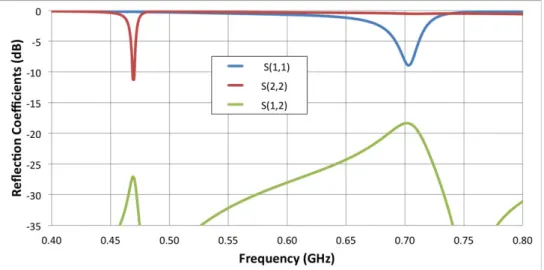
For the purpose of checking the multi antenna system performance, three configurations are also simulated, namely, (1): Antenna 1 at 470 MHz and Antenna 2 at 700 MHz, (2): Antenna 1 at 700 MHz and Antenna 2 at 470 MHz, (3): Antenna 1 and Antenna 2 at 470 MHz. The simulated reflexion coefficients are shown in the Figure 2.11, Figure 2.13 and Figure 2.15. Those results showed that the return loss is below -6 dB, thus we can say that the antennas are well matched. In order to have better performance for our antennas, we also have
to verify its isolation. For that purpose, the simulated results are shown the isolation between both antennas for each configuration in the previous figures. It is important to have a high isolation because it is the main parameters that can assure a good performance for the MIMO applications.
Figure 2.11: Config1 - the resonances of antenna 1 at 470 MHz and antenna 2 at 700 MHz
(a) (b)
Figure 2.13: Config 2 - the resonances of antenna 1 at 700 MHz and antenna 2 at 470 MHz
(a) (b)
Figure 2.14: The 3D realized gain of (a) antenna 1 at 700 MHz and (b) antenna 2 at 470 MHz
Figure 2.15: Config 3 - the resonances of antenna 1 at 470 MHz and antenna 2 at 470 MHz (The S11 and S22 results overlap each other)
(a) (b)
Figure 2.16: The 3D realized gain of (a) antenna 1 at 700 MHz and (b) antenna 2 at 470 MHz From the S-parameters simulated results, the configurations 1 and 2 show a good isolation that is greater than 15 dB at 700 MHz and 25 dB at 470 MHz. In theory, the obtained results are relative reasonable. Because in the configurations 1 and 2, each antenna operate at a different frequency, thus, the influence of the antenna to another will be significantly reduced. However, in configuration 3, 2 antennas operate at the same frequency, particularly, 470 MHz is the lowest frequency in the band requirement. Because the distance of 2 antennas (120 mm) rather short compared to wavelength at this frequency (about 638 mm), the isolation becomes quite low, approximately 6.3 dB. Therefore, the performance of the antenna can be affected. Nevertheless, this value may also be acceptable.
Figure 2.12, Figure 2.14 and Figure 2.16 illustrate the radiation pattern for each antenna at different frequencies. The radiation patterns are omnidirectional at 470 MHz and quasi-omnidirectional at 700 MHz. The realized gain of antenna is change from -2.2 dB to 1.87 dB at the frequencies of 470 MHz to 700 MHz, respectively. Therefore these parameters clearly indicate that this proposed antenna satisfies the specified requirement and it can be used in the mobile communication applications.
3.4.
Measurement Results
Figure 2.17: The prototype of antenna system.
Then the prototype of the antenna is realized (see Figure 2.17) and measured. Figure 2.18 shows the measured reflection coefficients of the proposed antenna. With a 0.73 pF – 3.05 pF capacitance value range of DTC, this antenna can be tuned all over White Space band with a reflection coefficient lower than -6 dB. Due to the fabrication error and the component losses, the bandwidth of antenna can be increased. However, it is not a good sign because those losses will affect the performance of antenna.
Figure 2.18: The measured reflection coefficients at the different DTC state.
The main objective of this chapter is to understand the control method and to test the characteristics of DTC component by integrating it in to a simple antenna. Firstly, the
influence of this component on the reflection coefficient is reviewed and confirmed. Thanks to the change of I2C control signals that are provided by Mbed microcontroller, the capacitor value of DTC is varied. Thus, resonant frequency of antenna can be shifted on the required frequency band. Because the operating band of the antenna is quite low, the measurement of antenna radiation field becomes difficult. However, at the end of chapter 3, the measurement of antenna efficiency, which uses DTC component will be introduced. By using the results of measurement in the easily measurable frequency and simulation results in low frequency to estimate the relative performance of the antenna.
3.5.
Approach of Antenna Diversity System
Disadvantages of the low-frequency multi reconfigurable antenna are the narrow bandwidth, worse efficiency and low isolation. Besides, according to the development of technology, the carrier aggregation is a trend to improve the spectrum usage efficiency. Based on the MIMO reconfigurable antenna, which is presented above, an approach of antenna diversity system is proposed to solve the drawback of low-frequency reconfigurable antenna and to support for the carrier aggregation. Firstly, two reconfigurable resonators are connected to each other via a simple divider. The isolation problem between 2 antennas that is mentioned in section 3.3 has been solved. By using ADS software and the .snp file is provided from HFSS, the simulated S-parameters of proposed system is shown in the figures below.
(a) Single resonator (b) Double resonators Figure 2.19: Bandwidth enhancement of proposed approach
In terms of reflection coefficient, the proposed approach presents a good improvement of bandwidth (contiguous and non-contiguous. As introduced in Figure 2.19, thanks to the use of 2 capacitors that have slightly different value (2.9 pF and 2.82 pF), 2 resonant frequencies are created. Thanks to the combination of these resonances, the bandwidth of the antenna can be increased (from 4 MHz to 8 MHz). On the other hand, due to the flexibility of 2 reconfigurable resonators, the carrier aggregation spectrum can be easily achieved (Figure
Figure 2.20: Carrier aggregation non-contiguous spectrum
In terms of radiation pattern, antenna performance is increased when two resonators operate at the same frequency. The simulation results with HFSS software prove that the radiation efficiency of antenna increased from 40% (single resonator) to 58% (double resonators) and realized gain increased from -2.18 dB (single resonator) up to -0.18 dB (double resonators).
(a) (b) (c) Figure 2.21: 3D realized gains of (a) resonator 1, (b) resonator 2 and (c) double resonators
3.6.
Envelope Correlation Coefficient (ECC)
In general, the correlation between the signals received by the two antennas can be evaluated through the Envelope Correlation Coefficient (ECC), ρ!. To achieve a reduction in
signal fading and a higher level of diversity gain, ρ! must be lower than 0.5.
Configuration 1 Configuration 2 Configuration 3
Resonator 1 470 MHz 700 MHz 470 MHz
Resonator 2 700 MHz 470 MHz 470 MHz
Table 2.3: the description about 3 different configurations
In our case, we have 3 configurations, (1) resonator 1 at 470 MHz and resonator 2 at 700 MHz, (2): resonator 1 at 700 MHz and resonator 2 at 470 MHz, (3): resonator 1 and resonator 2 at 470 MHz. By using Scilab, the envelope correlation coefficient is calculated;
the program code is given in Appendix 2. Thanks to HFSS simulation, we exported the data in radiation pattern for each configuration into the type of table. And then, ρ! can be calculated
by comparing the data between two different configurations at the same frequency. The formula of ECC is shown below:
470 MHz Configuration 1 Configuration 2 Configuration 3
Configuration 1 0.475 0.219
Configuration 2 0.475 0.287
Configuration 3 0.219 0.287
Table 2.4: The ECC value of three configurations at 470 MHz
700 MHz Configuration 1 Configuration 2 Configuration 3
Configuration 1 0.0418
Configuration 2 0.0418
Configuration 3
Table 2.5: The ECC value of three configurations at 700 MHz
At 470 MHz, we obtained ρ!= 0.475 for the first and the second configurations. After
that the comparison is also made for the first and third configurations and I obtained ρ!=
0.219 while for the second and third configurations I managed to get ρ!= 0.287. Then I
compared the first and the second configurations at 700 MHz and the result was ρ!= 0.0418.
We can conclude that our ECC were verified since all ρ! were below than 0.5.
4.
CONCLUSION
This chapter presented an overview of reconfigurable components especially digitally tunable capacitor (DTC). Since this is a relatively new product, the component control unit is also unusual as the other common components. Therefore, using a microcontroller to control this component is necessary. Mbed LPC1768 Microcontroller was chosen due to the ease of use and ability to provide SPI or I2C signal, thus, we can control DTC. By using the evaluation board, the basic characteristics of PE64005 DTC is measured and compared to the information that provided by the datasheet, thereby confirming the use of this device in reconfigurable antenna is feasible.
A reconfigurable antenna that was integrated the DTC has been designed and presented. The proposed antenna operates for Whitespaces applications at the frequency of 470 - 700 MHz. An antenna prototype is fabricated and measured. The S-parameters results show a good agreement between the simulation and measurement. Based on this design, an approach is proposed. By connecting 2 resonators, the proposed antenna it has shown a significant improvement about the bandwidth, radiation efficiency as well as the spectrum usage
different configuration are calculated by using a Scilab code. It confirms the good performance of antenna system for MIMO and diversity applications.

![Figure 2.5: The UHF band antenna based on a spiral-shaped monopole [32].](https://thumb-eu.123doks.com/thumbv2/123doknet/12975870.377993/39.892.113.781.354.703/figure-uhf-band-antenna-based-spiral-shaped-monopole.webp)

![Figure 3.1: The first GSM phone with an internal antenna: Hagenuk Globalhandy [1].](https://thumb-eu.123doks.com/thumbv2/123doknet/12975870.377993/56.892.125.771.610.1100/figure-gsm-phone-internal-antenna-hagenuk-globalhandy.webp)
![Figure 3.2: Geometries of the quad-band antenna and measured S-parameters [3].](https://thumb-eu.123doks.com/thumbv2/123doknet/12975870.377993/57.892.117.778.389.642/figure-geometries-quad-band-antenna-measured-s-parameters.webp)
![Figure 3.4: Double planar inverted-E feed structure antenna and measured S-parameters [5]](https://thumb-eu.123doks.com/thumbv2/123doknet/12975870.377993/58.892.130.782.264.478/figure-double-planar-inverted-structure-antenna-measured-parameters.webp)