HAL Id: hal-02946632
https://hal.archives-ouvertes.fr/hal-02946632
Submitted on 16 Apr 2021
HAL is a multi-disciplinary open access
archive for the deposit and dissemination of
sci-entific research documents, whether they are
pub-lished or not. The documents may come from
teaching and research institutions in France or
abroad, or from public or private research centers.
L’archive ouverte pluridisciplinaire HAL, est
destinée au dépôt et à la diffusion de documents
scientifiques de niveau recherche, publiés ou non,
émanant des établissements d’enseignement et de
recherche français ou étrangers, des laboratoires
publics ou privés.
Damage mechanics applied to the seismic behavior of
concrete structures
Shahrokh Ghavamian, Ludovic Jason, Justine Bonenfant
To cite this version:
Shahrokh Ghavamian, Ludovic Jason, Justine Bonenfant. Damage mechanics applied to the seismic
behavior of concrete structures. European Journal of Environmental and Civil Engineering, Taylor &
Francis, 2011, 14 (6-7), pp.839-854. �10.1080/19648189.2010.9693265�. �hal-02946632�
Title of the journal. Volume X – no X/2002, pages 1 to n
behavior of concrete structures
Shahrokh Ghavamian* — Ludovic Jason** — Justine Bonenfant*
* NECS, 196 rue Houdan, 92300 SCEAUX, France sg@necs.fr
** CEA, DEN, DM2S, SEMT, LM2S, CEA SACLAY F-91191, Gif sur Yvette ludovic.jason@cea.fr
ABSTRACT. The seismic behavior of reinforced concrete structures is generally evaluated through modal spectral approaches, based on linear elastic analysis. In the case of seismic reevaluation of existing structures using traditional methods, since the nonlinear behavior of materials is not taken into account, these techniques often lead to an overestimation of the needs in reinforcement. In this contribution, it is proposed to highlight how including nonlinearity in the mechanical behavior of concrete and steel can improve the seismic evaluation of RC structures. For this purpose, a pushover technique is applied on an office building. Contrary to a classical approach, the progression of the failure mode and the mechanical degradation can be obtained and used to accurately elaborate the best retrofitting strategy. Some improvements of the constitutive laws are nevertheless needed if the use of this type of approaches is to be extended to more complex structures. However, the maturity of most constitutive models is not enough to allow industrial applications.
RÉSUMÉ. L’évaluation du comportement sismique d’une structure en béton armé passe généralement par une approche modale – spectrale, basée sur une analyse élastique linéaire. Pour des bâtis existants, ce type d’approche est pénalisant dans la mesure où le comportement non linéaire des matériaux n’est pas pris en compte et conduit le plus souvent à une surestimation des renforcements nécessaires. On propose donc ici d’évaluer l’intérêt d’introduire les non-linéarités matériaux par l’intermédiaire d’un calcul de type pushover appliqué à un bâtiment de bureaux. Contrairement à une approche classique, le mode de ruine et la dégradation de la structure peuvent être évalués et la nature du renforcement optimisée (localisation et quantité). Néanmoins, si l’exemple montre l’avantage d’une telle simulation dans une configuration simple, pour des applications plus complexes, des lois de comportement plus riches sont nécessaires. Si ces approches sont disponibles dans la littérature académique, leur niveau de maturité n’est sans doute pas encore suffisant pour envisager une application industrielle.
KEYWORDS: seismic evaluation, reinforced concrete, structures, nonlinear behavior MOTS-CLÉS: évaluation sismique, béton armé, structures, comportement non linéaire
1. Introduction
Many solutions are available to simulate the material nonlinear behavior, especially for concrete or reinforced concrete. Constitutive laws are developed to represent different effects: local or global scale, continuum mechanics or discrete approach, isotropic or anistropic behavior, monotonic or cyclic loadings. With the increase in computer capacity, it should be possible to achieve an appropriate description of many industrial problems. Nevertheless, the real situation is probably less optimistic.
Despite the scientific improvements on the understanding of the material behavior, the developments of appropriate theoretical approaches and the implementation of the associated numerical models, combined with the increase in the computer capacity, the applicability of recent approaches is not totally demonstrated. The questions on the reliability of the models, their range of validity, their numerical robustness or the definition and calibration of their parameters are not fully satisfying for industrial applications. That is why the transfer to civil engineers remains difficult. While, the interest for industrial applications is strong.
In this contribution, after a brief presentation of the existing models, the particular case of an industrial application using a nonlinear behavior is presented. It concerns a seismic evaluation of an office building for which a retrofitting solution is proposed. From this study, it is shown how taking into account the failure mode and the mechanical degradation through a nonlinear constitutive law enables to elaborate the best optimized retrofitting strategy. On the contrary, a classical approach based on an elastic linear analysis leads to a retrofitting solution which is much more intrusive and expansive and less respectful for the environment.
2. State of the art
In this part, a brief presentation of the approaches used for seismic diagnosis is proposed. From the choice of a nonlinear simulation, some available techniques are also presented. Finally, the isotropic damage constitutive law chosen for the application is described.
2.1 Seismic evaluation
When considering the seismic behavior of reinforced concrete structures, the methods can generally be divided into three parts: modal spectral analysis, equivalent static method (linear or nonlinear) and transient approach (linear or nonlinear).
In the first case, the analysis is based on a linear elastic modal technique. The fundamental modes of vibration of the building are computed by taking into account inertial and static loadings. From the vibration frequencies the seismic loading (acceleration) is obtained. It is added to static forces and the final stresses are computed by a linear elastic simulation to perform the design of the new building or to evaluate the capacity of an existing structure. Nevertheless, this type of computation does not take into account the energy dissipation related to the nonlinear behavior of the material. One solution is to determine a « coefficient of behavior » that reduces the seismic forces. But the choice of this coefficient is not totally well defined, and concerns the entire structure without any distinction between weak and strong sections.
Transient computations represent an appropriate alternative because they provide a more detailed estimation of the behavior and enable to study a large range of structures (even an irregular geometry for example). Moreover, these methods can be applied either with a linear or a nonlinear constitutive law. But in this case, they require a significant computational cost and are thus rarely applied.
The engineering use of these types of analyses is based on an elastic material behavior. But, even if the behavior coefficient enables to reduce the forces and thus reduce the required amount of steel reinforcement, the accuracy of the results is not totally satisfying for existing buildings. The pushover method can represent an interesting alternative, since the estimated capacity of the structure is taken into account through a nonlinear structural analysis. It is less costly than transient approach and enables to use nonlinear constitutive laws (Fajfar (2000), FEMA 273, ATC 40). The structure is submitted to an increasing lateral monotonic load, up to failure. This allows to obtain a more realistic path of degradation of the structure taking into account post-elastic material behavior and stress redistribution. From the global behavior curve, the possible equilibrium point is determined, where the resistance of the structure balances seismic loading. Contrary to modal spectral methods, the aim is not to define the differences between existing and a required steel reinforcement design solution but to characterize the “real” capacity of the structure with regards to in place rebars.
To use this technique, a representative robust and “simple” (for the calibration of the parameters especially) constitutive law is needed. In the context of seismic studies, it is indeed essential to be sure that the computation will be performed to the end and it will then provide suitable and sufficient information. It is to be noted that this paper focuses on the global retrofitting of reinforced concrete structures. That is why the chosen model has to be able to represent the mechanical degradation and the global behavior but does not need to characterize accurately the crack characteristics (crack opening for example).
2.2. Available nonlinear approaches
Many approaches have been developed to represent the mechanical behavior of reinforced concrete structures. They are based on theoretical models that can be classified, depending on the way the mechanical degradation is described (directly by discrete approaches or from internal variables with continuum models for example). Many solutions seem thus available to solve the industrial problem. In the following, a brief description is proposed.
One of the most direct solutions to model the mechanical degradation is to explicitly represent the discontinuity associated to cracking, from discrete crack approaches (De Borst et al, 2003 ; Ingraffea et al, 1985 or Leblond, 2003 for example). In the initial model, the crack propagates when the nodal force at the crack tip becomes higher than a criterion in tension (generally the tensile resistance). The node is then divided into two new nodes and the crack tip propagates. Some improvements have been added to this methodology (Ingraffea et al, 1985 for example) but in all cases the key point is the explicit description of the crack. This can only propagate along element edges of the mesh. It thus supposes, either the knowledge of the crack evolution before the simulation in order to adapt the mesh, or some remeshing techniques, which are numerically costly. “Meshless” methods (Belytschko et al, 1994 or Askes 2000 for example) are alternative solutions but serious issues related to the numerical robustness in 3D studies and computational costs remain unsolved for industrial applications.
Enrichment methods aim at improving the classical finite element method. For example, strong or weak discontinuity approaches (Fernandez et al, 2004 for example) are based on an enrichment of the finite element degrees of freedom to allow a discontinuity in the strain and/or displacement fields. Another method, proposed by Belytschko et al (1999) or Moes et al (1999) uses the partition of the unity property of the shape functions. This type of formulation is interesting because the crack path does not need to be meshed and the problem related to the mesh dependency is thus solved. Nevertheless, using this method supposes a significant increase in the computational cost. Moreover, even if an explicit meshing of the crack is not necessary, some sophisticated numerical tools are needed along its path for the integration. Finally, the extension of these methods to 3D problems is not fully achieved which limits the use of these techniques for representative industrial problems.
Contrary to the previous methods, other approaches are based on the continuum mechanics to simulate the concrete behavior. The discontinuity related to the crack is modeled through internal variables (damage, irreversible strains, oriented stress tensor, …) and not explicitly represented. It is this type of approach, which is classically used, in structural computations (Ghavamian et al, 2003). In damage models, which are often used, the cracking effect is taken into account in modifying the elastic stiffness. A damage variable, a scalar in case of isotropy or a tensor in
case of anisotropy, is thus defined. The strain – stress relation is generally written (Chaboche, 1979) as:
endo e ij Cijkl kl
[1]
with et e respectively the stress and elastic strain tensors and Cendo the degraded
elastic tensor.
The simplest approaches are isotropic with a scalar damage variable. The stress – strain relation [1] then becomes:
(1 )
ij D Cijkl kl
[2]
where C is the initial elastic stiffness, the strain and D the damage variable. D
generally depends on the tensile loads, from which cracks initiate and propagate (Mazars’ equivalent strain for example (Mazars (1984))). These models are simple to implement but are not fully representative in some cases, specially for complex load paths.
For example, the evolution of irreversible strains is not simulated by these approaches: a zero stress is related to a zero strain. Some solutions exist to represent this effect. For example, La Borderie (1991) defines an irreversible strain as a function of the damage variable. But the most direct solution is to include a plastic strain p, with the definition of a plastic yield surface. This surface (Grassl et al,
2002), (Hansen et al, 2001) (Jason et al, 2006) for example) is chosen as a function of the effects that have to be modeled (dilatancy, plastic threshold in tri-compression…). The relation [2] then becomes:
(1 ) ( p)
ij D Cijkl kl kl
[3]
If combining damage and plasticity significantly improves the formulation, it also imposes some constraints: increase in the number of parameters and difficulties in numerical resolution technique that tend to become very complex with the implicit iterative method used to solve the equations of plasticity. These methods have thus to be chosen only in cases where they are really necessary (eg. well description of unloading slopes).
The material anisotropy can also be taken into account. In this case, the damage is no more described by a scalar variable. For example, smeared crack models, initially developed by Rashid (1968) or de Borst et al (2003) consider that concrete is initially isotropic. But when one of the principal stresses exceeds a given threshold, a « crack » initiates in the orthogonal direction. The isotropic relation is then replaced by an orthotropic law. When cracking directions remain steady with the loadings, the formulation is called « fixed crack model ». These approaches give
direct information about the cracks (as the directions of the orthotropic tensor and of cracking are the same) but some blocking effects can be observed on the stresses (Rots, 1992). One way to solve this problem is to use « rotating crack models » in which the directions of orthotropy rotate with the directions of the principal stresses. In all cases, the interest of anisotropic models is to provide direct information about the crack direction, but they also require heavy computational cost. That is why a preliminary study would be of great help before deciding to use, or not, this type of formulation (as a function of the loadings for example).
From a physical point of view, the crack closure effect may be very important, especially when concrete is submitted to alternated loadings. During the unloading, microcracks gradually evolve (closure) and the global stiffness increases while the damage remains constant. Taking into account this closure effects requires an improvement of the numerical model (for example a decomposition of the stress into negative and positive parts (La Borderie, 1991)). But these evolutions may induce strong discontinuities with consequences on the numerical robustness.
Using softening constitutive laws also requires special care to overcome the well-known mesh-dependency problem. After microcracking that takes part during the first step of the nonlinear behavior, a macroscopic effect appears through a damaged region with the localization of strains. The stresses at a material point can not be described locally any more but have also to take into account the interaction with the surrounding environment (Askes, 2000). The mechanical state of the material within the region cannot be correctly described by classical continuous models (Peerlings et al, 2001). Damage relations, as mentioned above, provide results that depend on the refinement and the direction of the mesh. In the case of an extremely refined mesh, a fracture may occur without any dissipation of energy. To solve this difficulty regularized techniques could be used, such as integration method (Pijaudier-Cabot et al, 1987), gradient (Peerlings et al, 1996) or energetic (Hillerborg et al, 1976). Even if these methods manage to avoid the mesh dependency, the question of their applicability on industrial problems remains open (increase in the numerical cost, choice of the internal length or any other specific parameter, …)
From this brief description, one can conclude that numerous solutions are offered to study complex real application structures. To choose the appropriate model, the engineer may have to answer some of the following questions:
- What is the range of validity of the constitutive law? This is generally obtained from validation studies performed at different scales: elementary specimens, structural or industrial cases,
- Which effect is to be simulated (irreversible strains, dilatancy with plasticity, crack closure, orthotropy, …)? And, is the constitutive model adapted to the type of loadings?
- How many parameters are associated to the model and how are they calibrated (calibration from classical tests or user dependant parameters)? - Is the model applicable to industrial applications (especially in term of
computational cost or numerical robustness)?
From the answers, it becomes possible to choose the appropriate model for a given application.
2.3 Description of the chosen constitutive laws (steel and concrete)
Pushover analysis is based on a finite element computation using nonlinear constitutive laws. In our case, the isotropic damage law, initially developed by Mazars (1984), is chosen. Given the type of loading (stress state), the numerical robustness and the availability of the model in different finite element codes (well documented law and calibration technique from classical elementary tests), this model is appropriate for the study. Its simplicity also offers acceptable cost in computation.
The mechanical behavior is described through a scalar variable D (for Damage) representative of the microcracking of concrete. The degradation is applied on the elastic stiffness as bellow:
(1 )
ij D Cijkl kl
[4]Mazars proposes the use of an equivalent strain indicator based on the tensile state of the material to determine the cracking and crack evolution:
3 2 1
(
)
eq i i
[5]where i designs the positive principal strains. The loading surface g is defined by:
( , ) ( )
g D D D [6]
D is equal to the maximum value of D during the history of loading, D = Max /t
(D, 0). The evolution of D is controlled by a law that distinguishes tension and compression (due to a concrete compressive strength which is ten times higher than the tensile one) by introducing two scalar variables Dt and Dc:
0 0 , , , , 0 , 3 , 2 1 if ( ) ( ) ( ) ( ) ( ) (1 ) 1 exp[ ( )] else 0 eq D t t eq c c eq D t c t c t c eq t c eq D t c i i t c i eq D D D A A D B D [7]
D0 is a model parameter and represents the initial threshold from which damage
initiates. Dt et Dc represent the tensile and compressive parts of damage. At,c et Bt,c
are four model parameters. The weights t and c are computed from strains. In
tension, t = 1 and c = 0. In compression, t = 0 et c = 1. reduces the damage
effect when the material is loaded in shear.
The damage evolution is finally determined by Kuhn–Tucker conditions:
0, 0, 0
g D gD [8]
Numerical values of the parameters are adjusted in order to obtain the response of the model as close as possible to a concrete tensile and compressive stress strain plot obtained from a standard code (eg. CEB/FIP, 1993), corresponding to the
characteristics of the concrete of the structure. Localization phenomena is overcome by adopting an almost uniform mesh size for model.
Concerning steel, the constitutive model used is a classical elasto-plastic kinematic linear hardening model.
3. Damage mechanics applied to the seismic behavior of a reinforced concrete structures
3.1. Presentation of the structure
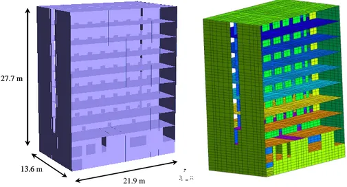
The office building considered in this contribution is a 9 story reinforced concrete structure. Figure 1 illustrates the geometry. The thickness of the walls and the slabs are respectively equal to 18 and 25 cm. The bracing of the building for the horizontal loads is obtained by the shear walls. Nevertheless, during the design, the actions have been underestimated, with consequently too many openings in the walls and insufficient steel reinforcement.
To propose a retrofitting solution, a traditional engineering approach would be carried out with a modal spectral technique to evaluate the stresses and to determine the required steel ratios. These would have then been compared with the existing
rebars to determine the presence of any weak area critical to the stability of the structure.
For the purpose of a pushover analysis, the FE model is enriched with the existing reinforcement. Figure 2 illustrates the mesh, where the slabs are represented using shell elements. Steel reinforcement of slabs and walls are represented by special shell elements with unidirectional behavior along each rebar direction.
21.9 m 13.6 m 27.7 m 21.9 m 13.6 m 27.7 m
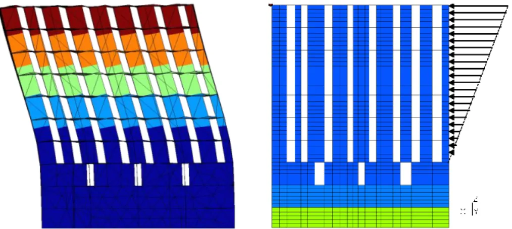
Figure 1. Building geometry Figure 2. Finite element mesh The static loadings are the body weight of structural elements, permanent loads G (between 100 and 250 kg/m²) and operating loads Q (250 kg/m²). The mass associated to these loads are also taken into account to evaluate the seismic loading. After having applied the gravity loads, a pushover lateral load is gradually applied on the part of the building out of ground. The vertical distribution of the lateral load is determined by the shape of the principal mode of vibration in the chosen direction (X and Y) (Figure 3).
Fmax du point pilote Fmax Fmax Fmax du point pilote
Figure 3. Left : Principal mode of vibration. Right : Lateral pushover loading
For the lower part of the building under ground, soil-structure interaction is taken into account by considering appropriate boundary conditions.
Nonlinearities are considered to take place in all walls and slabs (absence of beams and columns). Considering the nonlinear material models, all numerical parameters were chosen to fit characteristics specific to the project: elastic modulus, Poisson ratio, tensile and compressive strengths of concrete, elastic modulus and yielding stress of rebar steel. These are summarized in the following table. It has to be noticed that other material properties are also used to determine the softening of concrete. While normal values were used here, more specific values may be chosen upon available experimental data.
E (MPa) (-) ρ (kg.m-3) fc (MPa) ft (MPa) fe (MPa) Concrete 32 000 0.2 2 300 25 2.1 Steel 200 000 - 7 850 - - 400
Table 1. Concrete and steel properties
3.2. Results of the simulation
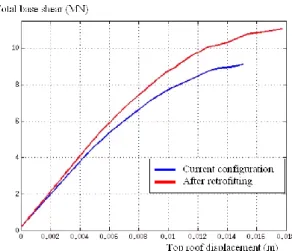
The pushover method enables to determine the global behavior of the structure. Figure 4 presents, as a function of the horizontal top roof displacement, the total force applied on the wall.
Figure 4. Capacity diagram: foundation shear force versus top roof displacement
This shows a monotonic evolution, quite linear at the early stages before reaching a maximum displacement that corresponds to one of the failure modes of the structure, which corresponds to excessive tensile strain in rebars. Other failure modes could be: concrete crushing, shear cracking, interstory drift, loss of foundation. Here, the large strain in steel is caused by the failure of the wall due to strong shear force (Figure 5). This is the key feature of a nonlinear analysis that provides access to the failure mechanism of the structure.
The pushover method consists in comparing the capacity diagram of the structure to seismic load demand diagram, and determines the equilibrium point (demand point).
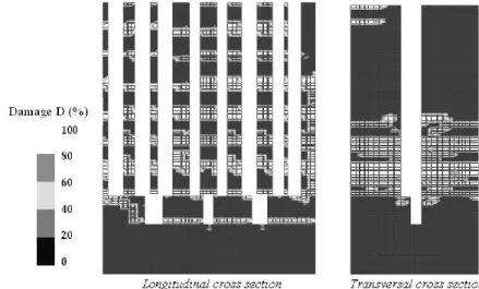
At demand point loading, Figure 6 illustrates the damage distribution (D variable of the concrete constitutive model), which indicates the mechanical degradation of concrete. When D=0, concrete is at its full capacity, while at D=100% it loses all its mechanical properties.
Figure 5. Deflection of the model (cm). Left: at the moment of the first failure point (see Figure 4), Right: at a loading point way above the failure point (9 MN shear)
Figure 6. Damage distribution at demand point
From Figure 6 we can observe that:
- For longitudinal walls (left image) concrete damage is rather spread all over the structure. At almost every story, each wall is damaged through their entire width. This behavior is very probably due to door openings that significantly affect the stiffness of these walls to resist shear forces.
- For transversal walls (right image) degradations are more localized at lower stories where bending moment are the greatest.
As mentioned before, the main interest of nonlinear analysis is to be able to predict the maximum load capacity of the structure, and identify structural weaknesses, in order to elaborate the best retrofitting solutions. Here one retrofitting solution could be the increase in thickness of walls from 18 to 33cm with additional 18cm²/m reinforcement in both horizontal and vertical directions in order to improve the capacity of the structure in terms of its resistance. Moreover, from damage distribution results it appears that the retrofitting may be applied only from stories 2 to 4.
It is interesting to indicate that a classical linear elastic analysis using a behavior factor of 2 concluded in the retrofitting of almost the entire building. The choice of the value of the behavior factor is naturally questionable for an irregular structure as the one presented here.
Including these changes in the FE model, another pushover analysis allows to appreciate the strength capacity improvement reached (see Figure 7) where stability criteria are this time verified. As expected, the retrofitting increases both shear force capacity and slightly the ductility of the structure to ground motions along the X direction. Figure 8 shows the damage distribution at the new demanding point.
Figure 7. Effect of retrofitting on the demanding diagram
For the sake of comparison, the same building studied by traditional linear elastic modal spectral analysis and the use of a behavior factor of 2 concluded to a generalized insufficient reinforcement. The difference in retrofitting cost between the two approaches was then roughly estimated to at least one million euros. To this one could add the organization difficulties of the job site and employee relocation (more important in case of generalized retrofitting) and environmental impact.
4. Conclusions
With significant increase in risk management and sustainable development issues related to construction works, the attraction for the use of advanced simulation tools and techniques is becoming more and more obvious. This is even stronger in earthquake mitigation, where structures are submitted to severe conditions.
While for new projects linear elastic analysis is in most cases sufficient to encounter for seismic action, this is mostly not the case for existing structures where these methods could lead to wrong diagnosis or overestimation in retrofitting needs.
The example shown in this contribution clearly indicates the interest of performing nonlinear simulations using nonlinear constitutive laws. Such studies lead to both the capacity of the structure to withstand a given ground motion, and provide indication on structural weaknesses. Such analysis techniques also allow to evaluate the efficiency of retrofitting solutions and thus their optimization. In this project the economical benefit appears quite clearly, with the proposal of a less aggressive retrofitting solution allowing to maintain the building functional for most of its occupants.
However, the situation is more complicated when it comes to a wide range of industrial applications, since the validity of nonlinear constitutive models are constrained to specific areas (loading conditions, geometrical configurations, …). The cost in preparing appropriate FE modeling, and computation are usually put forward by engineers to explain why these techniques are not used. The experience shows that quite often strong difficulties arise: lack of reliable information on models and their validity, lack of input data calibration techniques, numerical robustness, and cost.
That is why, in spite of significant improvements in computation capacities (size and speed), nonlinear application still require great amount of time, human and hardware resources to ensure reliable studies.
5. Références
Askes H., “Advanced spatial discretisation strategies for localised failure. Mesh adaptivity and meshless methods”, PhD Thesis, Delft University of Technology, Faculty of Civil Engineering and Geosciences, 2000.
ATC 40, “Seismic evaluation and retrofitting of concrete buildings” – Volume 1, Applied
Technology Council, Reoirt n° SSC 96-01, November 1996.
Belytschko T., Lu Y.Y., Gu L., “Element-free Galerkin methods”, International Journal of
Numerical Methods in Engineering, vol. 37, 1994, p.229-256.
Belytschko T., Black T., “Elastic crack growth in finite elements with minimal remeshing”,
de Borst R., Remmers J.C., Needleman A., Abellan M.A., “Discrete vs smeared crack models for concrete fracture: bridging the gap”, Proceedings EUROC, 2003, p.3-17.
CEB/FIP Model Code 1990 (Design Code). Comite Euro-International du Beton. 1993. Chaboche J.L., “Le concept de la contrainte effective appliqué à l’élasticité en presence d’un
endommagement anisotrope”, Colloque Euromech, 1979.
Fernandez L.E., Ayala G., “Constitutive modeling of discontinuities by means of discrete and continuum approximations and damage models”, International Journal of Solids and
Structures, vol. 41, 2004, p. 1453-1471.
FEMA 273, “NEHRP guidelines for the seismic rehabilitation of buildings”, Federal
Emergency Management Agency, October 1997.
Fajfar P. “A nonlinear analysis method for performance based deismic design”, Earthquake
Spectra, vol. 16, 2000, p. 573-592.
Ghavamian S., Delaplace A., “Modèle de fissuration pour le béton. Projet MECA”, Revue
Française de Génie Civil, vol. 7, 2003.
Grassl P., Lundgren K., Gylltoft K., “Concrete in compression: a plasticity theory with a novel hardening law”, International Journal of Solids and Structures, vol. 39, 2002, p. 5205-5223.
Hansen E., Willam K., Carol I., “A two-surface anisotropic damage/plasticity model for plain concrete”, Proceedings of FRAMCOS 4 Conference, 2001.
Hillerborg A., Modeer M., Petersson P.E., “Analysis of crack formation and crack growth in concrete by means of fracture mechanics and finite elements”, Cement and Concrete
Research, 1976, p. 773-782.
Ingraffea G.A.R., Saouma V., “Numerical modeling of discrete crack propagation in reinforced and plain concrete”, Fracture Mechanics of concrete: Structural application
and numerical calculation, 1985, p. 171-225.
Jason L., Huerta A., Pijaudier-Cabot G., Ghavamian S., “An elastic plastic damage formulation for concrete. Application to elementary tests and comparison with an isotropic damage model”, Computational Methods in Applied Mechanics and
Engineering, vol. 195, 2006, p. 7077-7092.
La Borderie C., “Phénomènes unilatéraux dans un matériau endommageable”, Thèse de doctorat de l’université Paris VI, 1991.
Leblond J.B., « Mécanique de la rupture fragile et ductile, Etudes en mécanique des matériaux et des structures », Lavoisier, 2003.
Mazars J., “Application de la mécanique de l’endommagement au comportement non linéaire et à la rupture du béton de structure”, Thèse d’Etat, Université Pierre et Marie Curie, 1984.
Moes M., Dolbow J., Belytschko T., “A finite element method for crack growth without remeshing”, International Journal of Numerical Methods in Engineering, vol. 46, 1999, p. 131-150.
Peerlings R.H.J., de Borst R., Brekelmans W.A.M., de Vree J.H.P., “Gradient enhanced damage for quasi brittle materials”, International Journal for numerical methods in
engineering, vol. 39, 1996, p. 3391-3403.
Peerlings R.H.J., Geers M.G.D., de Borst R., Brekelmans W.A.M., “A critical comparison of non local and gradient enhanced softening continua”, International Journal of Solids and
Structures, vol. 38, 2001, p. 7723-7746.
Pijaudier-Cabot G., Bazant Z.P., “Nonlocal damage theory”, Journal of Engineering
Mechanics, vol. 113, 1987, p. 1512-1533.
Rashid Y.R, “Ultimate strength analysis of prestressed concrete pressure vessels”, Nuclear
engineering and design, vol. 7, 1968, p. 334-344.
Rots J.G., “Removal of finite elements in smeared crack analysis”, Proceedings COMPLAS