Development of a Human Body Upper Arm
Dynamic Model for Compensation and Control of
a Body Mounted Robot
by
Nicholas Hensel
B.S. Mechanical EngineeringB.S. Electrical Engineering
Rochester Institute of Technology (2014) Submitted to the
Department of Mechanical Engineering
in Partial Fulfillment of the Requirements for the Degree of Master of Science in Mechanical Engineering
at the
MASSACHUSETTS INSTITUTE OF TECHNOLOGY
MASSACHUSETTS INSTITUTE OF TECHNOLOGY
JUN 21
D
LIBRARIES
ARCHIVES
June 2017C 2017 Massachusetts Institute of Technology All rights reserved.
Signature of A uthor ... .. . . .. . . . Department of Mechanical Engineering
May 12, 2017
Certified by ... .
. . ...
....
H. Harry Asada Ford Professor of Mechanical Engineering Thesis Supervisor
Accepte d by ...
Rohan Abeyaratne Chair, Department Committee on Graduate Students
Development of a Human Body Upper Arm
Dynamic Model for Compensation and Control of
a Body Mounted Robot
by
Nicholas Hensel
B.S. Mechanical EngineeringB.S. Electrical Engineering
Rochester Institute of Technology (2014) Submitted to the
Department of Mechanical Engineering
in Partial Fulfillment of the Requirements for the Degree of Master of Science in Mechanical Engineering
at the
MASSACHUSETTS INSTITUTE OF TECHNOLOGY
June 2017
C 2017 Massachusetts Institute of Technology All rights reserved.
Signature of Author ... Certified by... MASSACHUSETTS INSTITUTE OF TECHNOLOGY
JUN 21
D
LIBRARIES
ARCHIVES
/1aSignature redacted
Department of Mechanical EngineeringMay 12, 2017
Signature redacted
.1 H. Harry Asada
Ford Professor of Mechanical Engineering Thesis Supervisor
Signature redacted
A ccep ted b y ... ...
Rohan Abeyaratne Chair, Department Committee on Graduate Students
Development of a Human Body Upper Arm
Dynamic Model for Compensation and Control of
a Body Mounted Robot
by
Nicholas Hensel
Submitted to the Department of Mechanical Engineering On May 12, 2017 in Partial Fulfillment of the Requirements for the Degree of Master of Science in
Mechanical Engineering
Abstract
Supernumerary Robotic Limbs (SRLs) are robotic manipulators worn on the human body which seek to augment the abilities of their wearers. A critical element to the design and implementation of these robotic systems is the development of a control framework which allows for intuitive control. The control of SRLs is further complicated by the relative motion of the manipulator with respect to its
environment due to motion of the human body. Developing a dynamic model of the human body on which an SRL is mounted can serve as a useful tool, both for understanding the configuration of the SRL with respect to its user and for controlling the mechanism given a well-structured task process model. Subspace identification was investigated as a possible technique for generating a dynamic model of the human body from a set of defined input and output data. To validate the potential applicability of this approach, a simulated system was developed to model simple human arm reaching motions. From this simulated system, a set of virtual measurements were made to construct input/ output data sets. Subspace identification applied to these data sets indicated the applicability of the approach.
Further testing was then conducted via the development of an experimental system for measuring actual human reaching motions. Using appropriate measurements, the simulation framework was reproduced with a physical system. Applying
subspace identification techniques to the real data, a dynamic model was produced which could effectively reproduce the arm configuration. The success of both the simulated and experimental systems indicates that subspace techniques may be appropriate for generating human body dynamic models.
Thesis Supervisor: H. Harry Asada
Contents
Chapter 1: Introduction... 11
1.1 Hum an Augmentation... 11
1.2 Supernum erary Robotic Limbs ... 12
1.2.1 Advantages and Challenges of SRLs... 12
1.2.2 SRL M ounting Options ... 14
Chapter 2: Upper Arm Supernumerary Robotic Limb... 16
2.1 Upper Arm SRL Design... 16
2.2 SRL Control ... 18
2.3 Selected Control Paradigm ... 20
2.3.1 Task Selection ... 20
2.3.2 System Control Framework... 23
2.3.4 Hum an-In-The-Loop Correction... 25
2.3.5 Additional Discussion on the Body Dynamic M odel ... 26
2.3.6 Notes on Implementation of Robot Base Compensation... 28
Chapter 3: Body Dynamic M odel ... 30
3.1 Potential Approaches ... 30
3.2 Subspace Identification... 32
3.2.1 Application to Hum an Body M odelling... 35
3.2.2 Advantages and Disadvantages ... 37
Chapter 4: Sim ulated System ... 39
4.1 System Structure... 39
4.1.1 Hum an Body M odel... 40
4.1.2 Sim ulink Simulation ... 42
4.1.3 Sim ulated M easurements ... 44
4.2 Application of Subspace Identification... 45
4.2.1 Input/ Output Data... 45
4.2.2 M odel Generation ... 46
4.3 System M odel for Robot Positioning... 50
4.4 Discussion of Sim ulated Results... 53
4.4.1 System Order ... 54
4.4.2 Im pact of Sensor Quantity ... 56
4.4.3 Com m ents on M odel Pole Locations ... 58
Chapter 5: Experim ental System ... 59
5.1 Physical Setup... 59
5.1.1 Input Data Collection ... 60
5.1.2 Output Data Collection ... 62
5.1.3 Com bined Logging Approach ... 62
5.2 Data Processing... 63
5.2.1 IM U Data Conditioning...63
5.2.2 Im age Processing ... 64
5.3 Application of Subspace Identification... 66
5.3.1 Experim ental Data Cross Validation... 69
5.4 Task Execution with Arm Com pensation... 71
5.5 Discussion of Experim ental Results... 73
Chapter 6: Conclusion ... 75
6.1 Future Steps ... 76
List of Figures
Figure 1. Potential mounting regions for Supernumerary Robotic Limbs [1]. ... 14 Figure 2. 3DOF SRL consisting of a 5-bar linkage mounted on a rotating base. ... 17 Figure 3. Workspace of the 3DOF SRL mounted to the upper arm of a stick figure person sitting at a table, demonstrating the ability to reach a shared workspace w ith th e righ t h an d ... 17
Figure 4. Task process model for two people involved in the installation of a riser-support for roof-m ounted solar panels... 21 Figure 5. Task process model for an SRL augmented worker in the completion of a riser-support installation for roof-mounted solar panels... 22 Figure 6. Control framework for an SRL mounted to the human body consisting of a task process model in conjunction with body measurements and a model of the h u m an b ody ... 2 3
Figure 7. Block diagram describing a simple joint-wise SRL Controller...24 Figure 8. System control model with additional feedback path to body configuration from wearer observation of the current state of the SRL. ... 26
Figure 9. Hierarchical breakdown of system identification techniques... 30 Figure 10. Subspace identification algorithm presented by Van Overschee and De M o o r ... 3 4 Figure 11. Reference formulas and matrix forms used in the robust algorithm
presented by Van Overschee and De M oor ... 34 Figure 12. Framework for generation and utilization of the body dynamic model from su b sp ace ID . ... 37
Figure 13. High level structure of simulation model used for subspace identification te stin g ... 3 9
Figure 14. Simplified kinematic layout of a human upper-body model. ... 41 Figure 15. Wrist trajectories for left and right wrists given a set of randomly
generated reaching motions with a defined point-to-point reaching time of 800 ms. Position is given relative to the base of the torso where x is axially in front of the bod, y is axially to the left, and z is axially up. ... 42 Figure 16. High level Simulink block diagram of simulated system... 43 Figure 17. Right Arm Simulink subsystem block diagram for the simulated system.
... 4 3 Figure 18. Annotated Simscape model viewer for the simulated system identifying the modelled DOF as well as the virtual IMU frames used for generating simulated m easu rem en ts... 44 Figure 19. Training data set consisting of a sequence of 80 random one second
reach in g m otion s... 46 Figure 20. State space model produced from subspace identification applied to the sim u lated d ata set. ... 47
Figure 21. Comparison of simulated (solid -asi, as2, as3, ae) arm configuration angles with predicted dashed -(psi, ps2, ps3, pe) arm configuration angles
generated from the IMU data and body dynamic model... 47 Figure 22. Angular measurement error between simulated (actual) and model
predicted arm configuration angles. ... 48 Figure 23. Validation input/ output data set composed of 27 800ms random reaching m otio n s... 4 9
Figure 24. Comparison of validation data set simulated (solid - asi, as2, as3, ae) arm configuration angles with predicted (dashed -psi, ps2, ps3, pe) arm
configuration angles generated from the IMU data and body dynamic model
produced from the training data set. ... 50
Figure 25. Performance of simulated SRL in maintaining a specified tip location. Base of robot determined using state space model generated from subspace
identification in conjunction with simulated IMUs... 51
Figure 26. Comparison of the simulated "true" arm configuration angles (solid) and the model-predicted arm configuration angles (dotted) for use in robot end effector p o sitio n in g ... 5 2
Figure 27. Performance of simulated SRL in maintaining a specified tip location with the addition of integral feedback on tip position. Base of robot determined using state space model generated from subspace identification in conjunction with sim u lated IM U s. ... 53
Figure 28. Comparison of simulated (solid -asi, as2, as3, ae) arm configuration angles with predicted dashed - (psi, ps2, ps3, pe) arm configuration angles
generated from the IMU data and body dynamic model when only the z-axis sensor m easurem ents are applied. ... 56
Figure 29.Comparison of simulated (solid -asi, as2, as3, ae) arm configuration angles with predicted dashed - (psi, ps2, ps3, pe) arm configuration angles
generated from the IMU data and body dynamic model when the x and z axis sensor measurements are applied, with training data as input. ... 57
Figure 30.Comparison of simulated (solid - asi, as2, as3, ae) arm configuration angles with predicted dashed - (psi, ps2, ps3, pe) arm configuration angles
generated from the IMU data and body dynamic model when the x and z axis sensor measurements are applied, with validation data as input. ... 57
Figure 31. Eigenvalues for the state space model produced form subspace
id en tification . ... 58
Figure 32. Physical system setup with sensor-equipped shirt on lab bench and rough projection of camera field-of-views to demonstrate the workspace...60 Figure 33. Sensor-equipped compression shirt. ... 61
Figure 34. Camera output data during checkerboard-based image processing for arm-configuration detection. Left image shows the top-down camera field of view and right image shows the side-in camera field of view. ... 65
Figire 35. Experimentally generated set of innut IMU and output arm
configuration angle data for a set of random arm movements. ... 66
Figure 36. State space model generated from subspace identification applied to experim ental system ... 67
Figure 37. Comparison of measured (solid, m subscript) and model-predicted
(dashed, p subscript) arm configuration angles for the experimental system...68
Figure 38. Two sets of processed experimental body motion data. ... 69
Figure 39. Results of cross-validation for subspace model produced from
experimental training data. Each column of graphs shows a comparison of the measured (solid) and model-predicted (dashed) arm angles as well as the
corresponding error between these two values... 70
Figure 40. Execution of a basic task with arm motion compensation. Frames 1-3 demonstrate the arm reaching and grasping a workpiece. Frames 4-7 demonstrate arm motion compensation while an intermediate task is executed. Frames 8-9 demonstrate precise positioning with body motion. Frame 10 shows final task
List of Tables
Table 1. Qualitative tradeoff and comparison for SRL mounting locations on various p arts of th e body . ... 15
Table 2. Summary of some advantages and disadvantages to the subspace
Chapter 1: Introduction
The concept of augmenting the abilities of the human body with external tools is as old as mankind itself. The first simple wood and stone tools allowed their
users to hunt or dig more effectively. Clothing was developed as a means of shielding the body from the environment. When mankind began to engage in warfare, shields and body armor rapidly appeared and became more sophisticated.
Metallurgy was driven by the desire to make more advanced tools, both for hunting and to allow for more effective weapons and armor. After many thousands of years, the desire to augment and enhance the body has only grown. Correspondingly, technology has continuously advanced to try and accommodate humanity's vision of an improved person.
1.1 Human Augmentation
Exoskeletal robots are a natural consequence of the push to augment the human body. By using passive or active external actuators, systems mounted on the human body may enhance the strength, endurance, speed, and/or precision of the wearer. Exoskeletal devices have existed for over one hundred years, starting with gas powered passive systems [2] and quickly progressed to mobile machines which used a combination of hydraulics and electricity to amplify the strength of the wearer [3]. Modern exoskeletons span a range of applications, including medical support devices [4], augmentations for soldiers [5], and manufacturing worker assistance tools [6]. These are only some of the many areas in which exoskeletal systems are being applied.
Prosthetic devices are another technology akin to exoskeletal robots. While exoskeletons seek to improve the functionality of existing body parts, prosthetics seek to replace lost limbs with passive or active mechanisms. Extremely simple prosthetics, such as the immediately recognizable pirate's hook, replace a lost limb
with a highly simplified fixed tool which the wearer can use to aid in basic manipulation or locomotion tasks. Modern design of passive prosthetics has progressed to the point that it is even possible to argue the replacement limb can provide functionality which is superior to the lost limb, at least in the scope of certain tasks [7]. In addition to passive systems, actively actuated arms [8] and feet/legs [9] have been developed in recent years which demonstrate significant manipulation and control capabilities.
1.2 Supernumerary Robotic Limbs
In addition to exoskeletons, which augment the abilities of a user's existing limbs, and prosthetics which seek to replace lost functionality, a third class of robotic mechanisms exist. This category includes systems which add additional, unique degrees of freedom (DOF) which the wearer would not have without the addition of these devices. Called Supernumerary Robotic Limbs (SRLs) by the d'Arbeloff Laboratory for Information Systems and Technology at the
Massachusetts Institute of Technology (MIT), this class of devices offers the unique advantage of augmenting the user's body with additional fingers [10], arms [11, 12], or legs [13]. These augmentations allow the user to carry out manipulation tasks they would otherwise not be able to do as quickly or by themselves, potentially increasing their productivity. Through careful selection of the body-to-robot
interface location (mounting region for the SRL) and clever identification of control signals, the SRL is able to provide significant advantage to the user.
1.2.1
Advantages and Challenges of SRLs
Compared with exoskeletons and traditional fixed-base robotic manipulators, SRLs have a distinct set of advantages and disadvantages. First consider the
relative merits of SRLs against traditional exoskeletons.
An exoskeleton system seeks to mimic and extend the motions of its human wearer. Consequently, the goal for control of these mechanisms is often to
determine the intended motion of the user's limbs and then to generate actuator forces and torques such that these motions will be amplified [14]. This differs from an SRL, which can generate motions independent of the human body's joint
motions, and must therefore be controlled by signals which cannot necessarily be determined directly from the body's motion. The SRL is therefore advantageous when compared against an exoskeleton because it offers additional flexibility in manipulation and independence of motion from the body, at the cost of potentially increased control complexity.
SRLs also offer a unique set of tradeoffs versus standard robotic arms, especially in the context of assembly and manufacturing manipulation tasks. Traditional robot arms mounted on a fixed (or motion controlled and moving) base excel at repeated, precise pick-and-place operations or manipulations in a well-structured environment. However, they have limited capability when placed in an environment which requires frequent interactions with human users or in a poorly structured environment. Though advances have been made with compliant robotic systems for manufacturing tasks (for example Baxter [15]), there are still many areas where human workers are advantageous or necessary in completing
manufacturing or assembly tasks. SRLs offer a unique advantage to human workers in manufacturing or assembly tasks: they can both provide additional manipulation abilities to their wearers, acting as a collaborative second worker, as well as taking on tasks the wearer would otherwise have to execute, potentially reducing worker effort and fatigue. Compared with traditional robot arms, SRLs are limited in that they must act in a less precise environment, moving with the body they are
mounted to, as well as being limited in their potential weight, as they must be at least partially born by the human wearer.
1.2.2
SRL Mounting Options
A variety of body locations have been investigated as potential mounting
regions for SRLs by members of the d'Arbeloff Laboratory. Figure 1 is a diagram identifying some of the potential regions for mounting SRLs.
Shoulders
Upper Arm
Forearm Torso/Trunk
Figure 1. Potential mounting regions for Supernumerary Robotic Limbs [1].
Each of the regions identified in Figure 1 provide a unique set of benefits and challenges for implementation. In general, the closer a robot is to the center of mass of the human body, the less fatiguing the robot will be on its human wearer.
However, when placed at a more distal location, the robot can more effectively take advantage of body motion offered by action of the human body. Table 1 summarizes some key considerations and tradeoffs for each region of the body.
Table 1. Qualitative tradeoff and comparison for SRL mounting locations on various parts of the body.
Region Advantages Disadvantages
* Close t Only torso motion can contribute to robot
DOF, Torso * Lage contact region to center of mass, low mount fatigue to cannot easily leverage human motion for manipulations* Arms might easily interfere with robot workspace
* Robot weight can be distributed down to torso, low
fatigue * Comparatively small surface area to mount to
Shoulde Soleslittle displacementhedhihcaeofnjr* Relatively stable mounting region with comparatively * Robot potentially shares workspace with human
* Somewhat unconstrained workspace above shoulder head, high chance of injury
level
* Can leverage shoulder DOF for moving robot * Base of robot moves somewhat with motion of human
manipulator arm
Upper Arm * Distant enough from hand to have unique workspace * Somewhat distant from body center of mass, higher
relative to hand, large potential augmented manipulation risk of fatigue workspace
* Can most directly support hand workspace and share * Base of robot moves substantially with motion of Forearm directly in finger manipulation tasks human arm
* Small displacement required to act effectively with * Substantially distant from body center of mass, high
hands risk fatigue
* Leg muscles are large actuators, less likely to fatigue * More distant from precise manipulators (arms and
Leg compared with arms hands)
* Good region to aid in support of the human body * Not as well suited to manipulation task support
Given this set of potential mounting options considered and their relative merits, the next chapter will investigate some of the design and control
considerations involved in an SRL mounted to the upper arm of the human body. The control paradigm presented will then inform the motivation for the remainder of the thesis. As a whole, the purpose of this thesis will be to present the framework for the control of a new upper-arm-mounted SRL by the automatic generation of a human body model using the Subspace Identification technique. This body model will be generated both for a simulated version of the system, as well as from a set of experimentally generated data.
Chapter 2: Upper Arm
Supernumerary Robotic Limb
As discussed in the Introduction, SRLs are robotic mechanisms mounted to the human body which provide additional degrees of freedom to their human wearers. By not limiting these devices to the existing body joints, a variety of
additional considerations must be examined, including the tradeoffs compared against exoskeletons or traditional robot arms, the potential robot base locations on the body, and the added complexity of the control signals needed for these systems.
All of these concerns are discussed in the following sections. SRL research has been
conducted with respect to mechanisms mounted on various torso locations, the shoulders, and the forearm of the body. The upper arm remains an area that has not been investigated for use of an SRL mechanism. This region is appealing
because it allows the robotic mechanism to leverage the DOF offered by the human shoulder joint, while still being distal enough from the hand that the device can execute tasks collaboratively or in parallel with the hand without substantially interfering with hand motion.
2.1 Upper Arm SRL Design
As SRLs are mechanisms which are worn on and fully supported by the human body, weight and consequently the number of actuators is a major aspect of their design. Furthermore, the distance of the center of mass of the device from the body plays a major role in the fatiguing effect of the system on its wearer. It is therefore advantageous to locate the heaviest components as close to the body's center of mass as possible. In the case of a mechanism worn on the upper arm, this means placing as many of the system's actuators as possible at the base of the robot to minimize the torque on the wearer's arm. The outputs of each actuator must then be transmitted to the extremities of the robot.
The number of actuation elements needed in any SRL, as with any robotic manipulator, is another critical design element. By mounting the mechanism on the human upper arm, it is possible to leverage motion of the human body to aid in positioning the robotic manipulator. The motion needed in addition to that afforded
by the human body must be informed by the potential tasks being executed. In the
context of this investigation, a basic 3DOF structure was considered, allowing the robot's end effector to be positioned in three dimensions relative to the upper arm (and therefore the human hand).
Accounting for these two constraints on the system design (actuators located as close as possible to the base of the SRL, and three degrees of freedom), a simple mechanism was designed to serve as a framework for developing control strategies. Figure 2 shows a CAD mockup of the design chosen and Figure 3 shows the
reachable workspace of the mechanism when worn on the right upper arm of a stick figure sitting at a table.
Ls6
L35
ZR 1
XR
Figure 2. 3DOF SRL consisting of a 5-bar Figure 3. Workspace of the 3DOF SRL mounted to
linkage mounted on a rotating base. the upper arm of a stick figure person sitting at a
table, demonstrating the ability to reach a shared workspace with the right hand.
As can be seen in Figure 2, a five bar linkage design was used to generate planar motions, with two inputs 61 and 02 at the base of the robot. The plane of motion can then be altered by rotating the base about the Z axis by 60 with a set of spur gears. The workspace in Figure 3 was generated from a sweep of each joint
given a fixed set of link lengths as defined in Figure 2. The parameters used were:
* (60 , 61, 02) :
([-,
, [0, [0[,])
[rad]* {L1 2, L1 3, L2 4, L35, L45, L5 6} = {100, 200,80,210, 220, 220} [mm]
The focus of this thesis is not on the design of the robot mechanism. This brief overview of the mechanical design serves as a framework for identifying some of the key system components that have to be considered when generating the controller for an SRL mechanism. Namely, understanding the mechanical system is necessary in order to determine what data must be available for control of the robot, which will be discussed in the following section.
2.2 SRL
Control
The control demands of SRLs differ from both traditional fixed-base robotic arms and exoskeletons. While exoskeletons (generally speaking) seek to track and correct/enhance human motions by understanding the current actions and intent of the wearer, SRLs must simultaneously understand what the user is trying to do and then carry out actions which can support or augment that motion. If the SRL seeks only act in the same was as existing limbs, it does not truly provide additional degrees of freedom to the wearer. However, if the user must explicitly command the SRL to execute actions in place of carrying out natural movement, the mechanism becomes cumbersome to use and non-intuitive. It is therefore necessary to develop a control paradigm which either:
(i) Leverages signal data from the body which the user can readily provide without inhibiting their motion or interfering with the execution of tasks he/she already intended to carry out.
(ii) Infer the intent of the user and then automatically determine a set of actions which can aid in the execution of a given task.
Generally speaking, the first paradigm requires a clever means of sensing the state of the body other than directly measuring position and relating that to robot motion. One approach involves the use of position measurement of the human hand in order to determine grasping intent [16]. From the inferred grasping intent, the SRL then automatically acts to provide some actuation or grasping motion to the user. This system is useful in the case of a user who is unable to use both of their hands, instead leveraging a single functional hand and an SRL mounted on the forearm to carry out manipulation tasks that typically require two hands. This approach to SRL control is a promising one and requires investigation of novel ways to measure the state of the human body and extract intent without requiring the user to provide explicit input.
The second paradigm is particularly applicable in the context of manufacturing or assembly tasks which have a well-structured sequence of manipulation or control tasks readily described in a chronological sequence. Consequently, it is possible to generate a useful set of actions for a robotic manipulator using a combination of human body measurements and a
comprehensive task-process model. With an understanding of the current and past configuration of the user's body, their current state in the task execution cycle can be resolved, especially if additional system resources, including tools used in a manipulation task, are tracked. With this approach, the robotic manipulator can then be commanded to carry out pre-defined motions when the appropriate state in the manipulation task is reached [11].
SRLs also differ from traditional fixed-base robotic arms in that the
mechanism is attached to a surface that moves in a generally unknown way as the human wearer moves around in his/her environment. Due to this base motion, the position and orientation of the SRL changes constantly with time, introducing additional complexity to the control task. This is especially true if the intended
action of the SRL is to carry out some precise trajectory in a fixed coordinate system independent of the wearer's motion. The issue is reduced if all motions are carried out relative to the wearer's torso, especially if the SRL is mounted to the trunk region. However, in the case of an upper-arm mounted SRL, the configuration of the SRL relative to the body and the environment will change whenever the user moves his/her arm. Given the goal of the SRL is to provide some useful motion in
conjunction with arm motion, it is clear that some understanding of the body motion must be accounted for in any control strategy in order to achieve desired end
effector positioning.
The following section will present the system control framework considered for control of an upper-arm mounted SRL.
2.3 Selected Control Paradigm
Consider the SRL control approach in which manipulation tasks are generated from measurement of the human body in conjunction with a well-structured task framework. This approach is most effective in the context of
sequential manipulation and assembly tasks in which the human wearer is carrying out some well-defined process.
2.3.1 Task Selection
The use of an SRL is particularly useful in the execution of a task which: (i) Has a set of distinct steps that must be completed
(ii) Requires collaboration between two people or the use of a support tool, where the tasks of one person can readily be replaced by the SRL (iii) Is carried out in a poorly structured or unfixed environment in which a
traditional robotic arm is not appropriate
Given this set of task constraints, multiple manipulation and assembly tasks were considered as theoretical applications of an SRL. The case study presented here will be for assistance of a worker installing solar panels on a roof. This task
was selected because it is consistent with each of the above constraints. Workers installing solar panels on residential (or commercial) roofs must work in highly varied environments, often collaborating with one another in the completion of multiple tasks in the overall process of installing the solar panels. These tasks are well defined and repeated many times. Furthermore, solar panels are becoming increasingly prevalent, so assistive tools which could aid in their installation are worth developing [17].
Many potential tasks within the context of solar panel installation could be considered for study. Of these, the installation of riser supports prior to mounting solar panels was selected. Riser supports serve as the connection point between the roof and the base of the solar panels. The installation of these elements often
consists of a set of simple actions executed by a set of collaborating workers. Figure 4 below shows a general process model describing the flow of tasks between a pair of workers completing the installation of a riser support element[18].
Riser Support InstaNation - Two Person Task Cycle
Person 2
Right Hand pe
mao lamen shbng* bell il
Let Hand Fold back dhnb dwnonppped
plt
squemn cauddng
Right Harid ->gun toexinude ar
onwavtngpiae
Hold baled maApl wt
Lot Hand -0 ct"gn gun Mlong surface unden"id of
"""""""""of preppid Ph"t dhing
Figure 4. Task process model for two people involved in the installation of a riser-support for
As the model in Figure 4 shows, each worker executes a number of steps in conjunction with one another. The first worker must ready the riser for installation, and then wait for the second worker to prepare the riser and roof before finally installing the riser and completing the assembly task. In this manipulation task, two workers act together to complete the process because the number of
manipulation actions and tools used are more conducive to a pair of workers acting collaboratively rather than a single worker juggling all of the tools. However, by
augmenting a single worker with an SRL, it is possible to restructure the task so that it can be completed by on enhanced worker. Figure 5 shows one possible restricting of this task in which the user passes actions back and forth between himself/herself and the SRL mounted to his/her arm.
Riser Support Installation - SRL Augmented Single User (Task Description)
SRL Augmented User
Unamw R ace In GabIhfttm Hold phft I tont
FM Hand do -17 Fbek bOac Mhel -e- dof .n bodyp
me"l
SRLh Hol "d*Vt inv Pon *in* LOINpe AL dw --- --- WO n . %-I e C ML o nppeFigure 5. Task process model for an SRL augmented worker in the completion of a riser-support
installation for roof-mounted solar panels
While the revised task process model shown in Figure 5 appears to have more sequential steps, these steps can be executed more rapidly because the single
worker does not have to rely on interaction with another worker. Instead, he/she need only effectively interface with the SRL to efficiently carry out the installation and the second worker can operate completely in parallel or be dedicated to some other job.
It is clear that a process model can be generated to describe the movements demanded of the SRL. From this structured model, the SRL control framework can be further described and resolved.
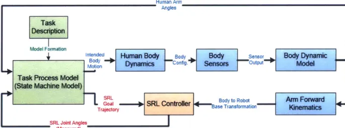
2.3.2 System Control Framework
Figure 6 shows one potential framework for characterizing the flow of information in a human-SRL task-process-model system.
Human Any_
Angles
Task Description
Model Formation
Intended Human Body Body Body Sensor Body Dynamic
Body ofg
Motion Dynamics "conig. Sensors "Outw Model
Task Process Model (State Machine Model)
_
_ _ k
SRLBoytRooAi
oar
Troy- SRL Controller -to Robo Arm Fowa
Traoecory Ease Transformation Wne atics SRL Joint Angles
(Measured)
Figure 6. Control framework for an SRL mounted to the human body consisting of a task process model in conjunction with body measurements and a model of the human body.
The block diagram of Figure 6 consists of subsystems. The task description is generated from the manipulation or control task being executed and converted to a task process model describing the general motions of the human wearer and SRL mechanism, as described in section 2.5.1.
As Figure 6 shows, the inputs to the Task Process Model consist of the time-history of the configuration of the human body (or arm angles), as well as the current state of the SRL. The outputs are the intended motion of the human body, which corresponds to some actual body motion via an unknown human body
dynamic model, and the desired trajectory of the SRL joints. Actual body motion is measured with some set of body-mounted sensor data, which is then interpreted by a dynamic model of the body to produce information on the configuration of the human arm (described as a set of joint angles). In this framework, the body dynamic
model acts as a sort of dynamic filter relating body sensor data to body
configuration data. It is not explicitly a model of the dynamics relating muscle/joint activation to joint accelerations, but instead a relationship between two types of achievable measurements. However, if the measured body dynamics are velocities or accelerations, the filtering between these time-derivatives of position will reasonably capture system dynamics.
The human arm configuration data can then be used both as the input to the Task Process Model, as well as serving to resolve the configuration of the base of the robot in a torso-centric control frame. This is critical to being able to precisely
position the end effector of the robot relative to the body for manipulation and control tasks. The calculated robot base transformation as and goal trajectory from the Task Process model can be used in the SRL Controller, shown in Figure 7.
SRL Controller (Per Joint) SRL Goal
Joint Controller Joint Dynamics Joint SRL Joint Angles
Figure 7. Block diagram describing a simple joint-wise SRL Controller.
The control scheme shown in Figure 7 describes a simple single input, single output approach to control in which each joint of the robot is individually controlled given a desired joint angle determined from knowledge of the configuration of the base, knowledge of the desired configuration, and an inverse kinematics model of the robot. The joint controller can be either a nonlinear controller, or a more classical controller which operates with a linearized model of the joint dynamics. The efficacy of this control scheme will be a function of the coupling between each of the joint motions of the robot actuator. Finally, measurements of the robot's joint configurations are assumed to be possible (for example, using encoders on each joint).
A critical aspect of this control paradigm is determination of the time history
of the human arm configuration given available sensor data. It is necessary to have an accurate and comprehensive dynamic model which is able to relate available sensor data to the current configuration of the human body. If a sufficiently accurate dynamic model can be generated, it may possible to predict the future state of the human body given the current state and a time history of measurement data. This would be extremely advantageous in this control scheme, as it would allow for the prediction of the body's configuration at future time steps. Prediction of body state could be used to compensate for the disturbance of the base of the robot, and predict the wearer's intent in executing tasks in the Task Process Model. The latter would then allow for a proactive control of the SRL, meaning the robotic manipulator could act on what the user is about to do rather than what the user has
already done, allowing for an overall more responsive system.
2.3.4 Human-In-The-Loop Correction
The control paradigm described in the System Control Framework and
diagrammed in Figure 6 demonstrates the interaction of the human wearer and the body mounted robot. In the approach diagrammed, the robot monitors and reacts to the human body in order to determine its current and future configuration.
However, it is reasonable to assume that the human wearer will further react to robot configuration and change pose to more precisely position the robot end effector at the desired location.
Consider the case where the robot is commanded to a specific location in space. While attempting to compensate for gross motion of the arm, the robot will inevitably have some small amount of error. Consequently, the wearer is likely to carry out slight adjustments in order to correct for this error. In this way, the human/robot system includes the explicit feedback driven by the robot control system as well as an internal human feedback path. Figure 6 can be modified to accommodate this additional consideration as shown in Figure 8.
Human Arm Angles
Task Description
Model FormationI
Inltended Human Body Body Body WVo'*I Body Subspace
Bod onl~C Model
Moin Dynamics "c'nfig" IMUs ccy Mde
Task Process Model wearer
(State Machine Model) ofSRL
SRGol - R otoe Body to Robot Arm Forward
Galct..y onrle ase Transform ationj' Kinematics
_ _ _ _ _ _ _ _ _ _ _ _ S R L J o in t A n g le s
(Measured)
Figure 8. System control model with additional feedback path to body configuration from wearer observation of the current state of the SRL.
The additional feedback path identified in Figure 8 includes both visual observation of the SRL configuration as well as any potential force feedback or propriceptive effect the robot might have when worn on the body. By considering the impact of this human-in-the-loop aspect of the system, it is possible to see an additional potential benefit of a body mounted robot: the human wearer is able to more finely position the robot through small motions of his/her body.
2.3.5 Additional Discussion on the Body Dynamic Model
The development of the so-called "Body Dynamic Model" is a key focus of this thesis. Consequently, further discussion on the meaning and implications of the expressed model form is worthwhile.
Consider the information flow expressed in Figure 6, particularly with respect to the relationship between the body motion output of the task process model and corresponding arm angle input. The referenced "Intended Body Motion" could be expressed as the muscle activation signals generated by the worker in carrying out the modelled task. Consequently, the "Human Body Dynamics" block expresses the transformation from neuro-electrical muscle signals to physical joint
motions. These
joint
motions are then captured by the "Body Sensors" and yield the captured sensor outputs. Only at this point is the model generated from system identification considered. The model expresses a relationship between the measured sensor data and the current physical configuration of the human arm, where the physical configuration can be determined from an additional measurement technique which would yield joint angles directly.Framed as a system identification problem, the "input" is the body sensor data measuring joint motions, the "output" is the body configuration, and the "system" is a sort of dynamic filter linking these two measurements. The power of this model is then in the ability to dynamically reconstruct the arm configuration from the measurement of joint motions without needing to use a more standard kinematic/dynamic chain model of the body.
Consider the problem without an intelligently determined dynamic model. It would be necessary to use a set of relative body motion measurements (linear accelerations and rotational velocities being the most readily accomplished) to calculate arm configuration angles. With this system structure, the position and orientation of each joint from the shoulder to the hand would have to be solved successively. Sensor measurement of the upper arm would be used to extract the upper arm configuration, then lower arm data in a likewise fashion. As the shoulder joint can rotate about three axes, the kinematics of this motion are not trivial.
Furthermore, for the result to be accurate it would be crucial to have an exact measurement of the location and orientation of the point at which sensor data is taken on the joint. Otherwise, the parameters necessary for generating a system
model would be inaccurate and would yield a false joint configuration. Additionally, given that the measurements considered are in the form of accelerations, double integration would be necessary in order to obtain the position at any given time, naturally resulting in delay from measurement to kinematic output. Such
It is under this set of considerations that the automatic construction of a dynamic body model/ dynamic filter is deemed a worthwhile endeavor. It is worth keeping in mind the observation that the developed model is likely to have some sort component resembling a second order integration, as the expressed model framework relates accelerations to positions. This prediction can later be
investigated in simulation and experimentation as a way of validating the system model produced.
2.3.6 Notes on Implementation of Robot Base Compensation
As identified in Figure 6 and Figure 7, one major goal of the developed dynamic model is to compensate for disturbance to the base of the robot (the other goal being the generation of robot control signals from the well-structured task model).
As previously discussed, a challenge in SRL control is the disturbance to the SRL produced from routine human motion. The base of the robot is rigidly (or semi-rigidly) attached to some part of the human body. Consequently, when its wearer moves that body part, the SRL is displaced. Therefore, to maintain accurate control of the end-effector location of the SRL it is necessary to continuously compensate for base disturbances.
One potential approach to base disturbance compensation is to continuously generate a transformation from the human torso to the robot base frame and from the robot base frame to its end-effector. Position/orientation of the end-effector can then be expressed in terms of the torso frame, with this configuration being a
function of the torso to robot base transformation, which is in turn a function of the arm configuration. Expressed generally, the transformations from torso to SRL (and back) are then:
TsoRase =
f
(Oshouder; Body Parameters) Forward Transformation, Torso to SRLCorrespondingly, the transformation from the base of the SRL to its end effector position and orientation (and back) are then:
TSRL ase g(OSRL; SRL parameters) SRL Forward Kinematics
TSRLjb ti= G(PEE; SRL Parameters) E SRL Inverse Kinematics
Combining these relationships, it is then possible to express the goal configuration of the SRL, i.e. the SRL tip frame, in the torso frame. Given this position in the torso frame, it is possible to obtain the set of robot angles necessary to achieve desired end effector positioning given a previously determined robot base disturbance. A demonstration of this technique will be shown in the Chapter 4 simulations.
Chapter 3: Body Dynamic Model
As identified in Section 2.5.2, the development of an accurate and comprehensive dynamic model of the human body is critical to the controlframework presented. The identification of a dynamic model given a set of input and output data is a well-studied problem under the umbrella of System
Identification [19].
3.1 Potential Approaches
Numerous approaches exist within the framework of System Identification. Figure 9 below (adapted from Professor H. Harry Asada's 2.160 Identification, Estimation, and Learning course notes [20]) describes a hierarchy of some of the many techniques available for system identification. Notice that at a high level, system identification is broken into two main categories: identification of linear and nonlinear systems, with the addition of the modelling of hybrid linear/nonlinear models using a Hammerstein-Wiener model in which the system is described as a combination of nonlinear inputs and outputs bounding a linear system.
System Identification
Linear System---- Combined System A--- Nonlinear System
-Hammerstein model -Wiener Model
Non-Parametric Model Parametric Model Global Locally' Direct Correlation State Transfer - Volterra Series
Method Method space function - Neural Net
- Time domain - Random Subspace Prediction- Information - Frequency excitation Method Error Method Theoretic Method
domain (ETFI) - Periodic
excitation - Lest sauares * Maximum
As Figure 9 demonstrates, there are many approaches to system
identification. A number of issues must be addressed in order to obtain a useful system model:
" How best to determine the appropriate model structure.
" How to ensure the data used for generating the system model is
sufficiently rich to capture the dynamics of the system. Alternatively, the data used for obtaining the system model must be sufficiently exciting to reach all of the states or operational conditions of the model.
" How to obtain a ground truth against which to compare the system model
outputs in order to ensure the model is producing meaningful outputs. * How best to design a methodology or experiment to generate the system
model.
In order to select an effective approach from this set of potential techniques, the context of the problem being investigated, i.e. the generation of a human body dynamic model, must be considered. Given the goal of this system is to use a set of body-mounted sensors as inputs to generate a set of joint angles, a generally
multi-input, multi-output paradigm is most appropriate to this problem. Furthermore, if the system dynamics can be captured with a linear system model, control
complexity can be reduced. It is also possible that some elements of nonlinear performance can be captured using a state space system representation [21]. By augmenting the state space with a set of states which are combinations of other system variables and using these augmented states as additional free parameters, it may be possible to model some linearized form of nonlinear system dynamics.
The addition of linearly redundant sensor measurements is another
technique by which it might be possible to capture system dynamics which may be nonlinear. Nonlinear dynamic system responses which might be observed between the interactions of these believed-to-be redundant measurements might be captured and modelled by the augmented state variables. The impact of potential input
redundancy on model formation can be considered in later sections by observing system performance with some of the available inputs removed.
Taking these considerations into account, the Subspace Method for system identification was selected as the approach to generating a human body model for this investigation. This approach accommodates the generation of a state space model representation of the system, which is a convenient means of obtaining a MIMO system model allowing for many input signals to be related to multiple output states (i.e. predictions of the human arm configuration). An additional
appeal of the subspace identification methodology is that the technique is still in its relative youth, with substantial opportunity to apply it to new problems and learn more about its strengths and limitations [21]. The following section will present an overview of the subspace identification technique, as well as discussing its
advantages and limitations. Finally, the framework for its application to the body dynamic model identification problem will be presented.
3.2 Subspace Identification
The goal of the subspace technique for system identification is to obtain a state space model of a system given a set of input and output data as well as the order of the state space model to be generated. Alternatively stated, given a set of input data u(t) and an output data set y(t), a state space model of the following form is produced:
x(t) = Ax(t) + Bu(t) + Ke(t) y(t) = Cx(t) + Du(t) + e(t)
In this expression, matrices A E 9"', B E ginx", C E %P"x, D E %Px"x, and
K E %nxP are state-space matrices for a set of m inputs, n states, and p outputs. In the most general form of subspace identification, each of these matrices is composed of free parameters. The identification problem then becomes one of generating the
identification involves resolving a set of (n - n) + (n -m) + (p -n) + (p -m) + (n -p) free parameters (all of the matrix elements). When all matrices are included in the solution, the problem becomes a combined stochastic/deterministic input/output identification problem.
Van Overschee and De Moor present a well-structured framework for the so called robust combined identification algorithm needed for generating the set of state matrices [21]. At its core, subspace identification relies on the construction of set of block Hankel matrices from both the input and output data sets. From these matrices, oblique and orthogonal projects are calculated to obtain a set of weighted projections. A Singular Value Decomposition (SVD) is then applied to the
projections both to obtain the system order (if not known a priori) as well as to resolve how to separate the SVD. From these generated matrices, a set of linear equations are solved to obtain the {A, C} matrices and then the {B, D} matrices as well as the noise covariance matrix K. Figure 10 from [21] presents this high level approach to subspace identification, with Figure 11 showing the relevant matrices that must be utilized in this formulation.
The approach presented in Figure 10 is one of multiple forms of the subspace identification algorithm. As the field has grown more sophisticated, multiple
modifications to the overall approach have been made to improve prediction results. Three of the main techniques that are used are the N4SID (Numerical algorithms for Subspace State Space System Identification), MOESP (Multivariable Output-Error State sPace), and the CVA (Canonical Variate Analysis). The main
differentiation between each of these techniques exists in the weighting matrices used to obtain the final model.
An excellent reference on the subspace identification technique and how it is formulated can be found in [22], in which the author first presents a general
framework for system identification and the relevant mathematical tools needed for subspace identification.
Figure 10. Subspace identification algorithm presented by Van Overschee and De Moor. i.--e f 0 0 D CA' 'B
t
o III U2 - - j-I il 112 U3 .. -- , U.- I a ". + I ..- .+ -r2U, U,+l U,+2 .U.. U ,+J
U,+l U.+2 14+
3 ... 1U+j
. . . . . . . . . . . . . . . U26-1 U2. U2.+l ... u2,+j-2
--
.past" "future" o \00
)c qs D C ef def A ) . (n+0x C ) ' A( I -12 .. -\ 4211 f-212 -. - L 2| a 4(M A2 ... Mi) Kill K112 .- I \ 211 K212 -. - K 2! / Kill K2 K21, -/all Ml - 12 M1 - 112 M.: - C11 M2 - C13 MA3 - C114 - C -C12 - 42 -12 . - 213 - A4 - 21. 0 x It 0) Ean0 W(.+I)(.Figure 11. Reference formulas and matrix forms used in the robust algorithm presented by Van Overschee and De Moor
Robust combined algorithm:
1. Calculate the oblique and orthogonal projections:
2. Calculate the SVD of the weighted oblique projection:
in _, = USVT.
3. Determine the order by inspecting the singular values in S and partition
the SVD accordingly to obtain U, and S1.
4. Determine ri and ri.1 as:
ri = USI1 2 , ]i_ = ri. 5. Solve the set of linear equations for A and C:
.31i C ..Zi + Kc. U + PV Recompute ri and ri_ 1 from A and C.
6. Solve B and D from:
B, D = arg min|11 -
)-( )
.)r.zi - K(B,D) .U1 127. Finally, determine the covariance matrices Q, S and R as:
Q S E,[( . pT pT | U012i-1I i+ \U2s I Ui+2 -1 112i (i = Ui+j 1 22+j-1,+i 114+2 Ui+3 U2i+l C CA CA2 CA*-I "past" "futurn 0 D CBI B CA' 3B 2 / D CB CAB CA. dil- ef UOI.-1 -( U, \ Y- W =W. -MA. - 11, 0 0 0 0 0 0 MA 2 -ril M01 - cl, 0 0 C1, 0 0 UO MII U2 .. - j-i \ III U2 U3 ... U) ... .. . ... .. . .. .
Ui-I Ui Ui+i -. - i+j-2
, Zi+1 =-, YT / -~P
-d f Up t ef K LC~ U, + -_,.HOfI ) - A. .H (D 1 0 ) - C.rt.H d Oi = Yf
/,
W" , Zi =
Y|W
MATIAB's n4sid() function is additionally useful for generating subspace models [23]. This function allows for substantial configuration of the identification
algorithm, including identification of the weighting methodology to apply to the inputs and outputs as well as control over the form of the state space model
generated. This algorithm was applied to generate the human body dynamic model.
3.2.1 Application to Human Body Modelling
In order to apply the Subspace Identification technique to obtain a dynamic model of the human body, it is necessary to formulate an equivalent input/output model for data that can reasonably be collected. The dynamic model must therefore be a relationship between readily achieved measurements. Measuring human intent, i.e. brain and muscle activation, is difficult, expensive, and potentially
invasive. Instead, it is more reasonable to use some set of body-mounted sensors as the system inputs, where this sensor data is used as a proxy for the true human intent. This is reflected in Figure 6, where the body dynamic model relates body
sensors to human arm angles, rather than the intended body motion. The output is a measurement of the human arm configuration, i.e. an equivalent set of joint angles which describes the configuration of the human upper body at any given time. Ultimately, as discussed in Section 2.5.3, the generated model is more of a
dynamic filter than a true body model, but should serve as an effective tool for SRL control. By relating body accelerations to joint angles, the dynamics of the system
are still captured.
Measurement of body motion can readily be accomplished with a set of multiple Inertial Measurement Units (IMUs), each of which captures three-axis linear acceleration as well as rotational velocities using a MEMs accelerometer and
gyroscope.
The measurement of human arm angles is a more challenging problem. One potential approach is to use each IMU in conjunction with some filtering technique, i.e. an Extended Kalman Filter, to obtain a set of Euler angles for the body part the
IMU is mounted to [24]. This approach is advantageous because it allows for a fully body-mounted sensor solution, allowing the generation of a body model in an
unstructured environment. However, the generation of the yaw Euler angle relies on use of magnetometer data from the IMU, which is generally somewhat
unreliable. Consequently, the yaw angle is prone to inaccuracy and drift.
Alternatively, a fixed reference measurement can be used to generate the arm configuration angles, i.e. using a camera or motion capture system to generate a wireframe of the body and then back-calculate the configuration angles from this wireframe. This approach is advantageous because it is not prone to drift and can be highly accurate depending on the data collection technique used. However,
having a fixed reference requires that data collection be done in a well-structured environment, which is a clear disadvantage to this data collection approach. Given the expressed value of an SRL is its usefulness for workers operating in a poorly structured environment, this requirement for generating the body dynamic model might be prohibitive. Though this restriction is disadvantageous to the overall system design, it is not prohibitive. By generating a dynamic model of the body, the arm configuration angles measurements are only necessary in an "offline" version of the system.
During "offline" operation, body measurements and fixed measurements are used to create the subspace model, making the generation of the model a sort of "calibration" cycle for the user. Then, in the "online" system, only the body mounted sensor data is necessary to generate the body configuration data. This is one of the advantages of generating the body dynamic model in this way; not only does it allow for prediction of future states, it also eliminates the need for measuring arm angles directly. Figure 12 diagrams this offline calibration! online performance
"Offline Calibration' -Model Generation
ntended Human Body Body
- Body 'cni~air-l
Motion Damics onfguratio MUS .Acclerometer Subspace Body Subspace
IdentficAtion modm
Global Frame Camera "urndn
IuAngisles e
"Online System" -Model Implementation
nended Human Body Body Body G Body Subpace Predicted
- Body 11 Arm -010
Motion Dynamics COnlhI IMUS .!-cI.. Model Angles
Figure 12. Framework for generation and utilization of the body dynamic model from subspace ID.
As Figure 12 demonstrates, in the offline mode the body IMUs and global camera system are used as the inputs and outputs to a subspace identification process which yields the dynamic model for the human body. This dynamic model can then be used in the online mode to generate a prediction of the arm angles given only the data from the body IMUs.
3.2.2 Advantages and Disadvantages
The subspace identification technique offers a powerful tool for generating a system model and is appealing for its use in generating a dynamic model of the body in the presented case. However, there are a number of potential disadvantages to this approach. Table 2 summarizes some of the potential advantages and
![Figure 1. Potential mounting regions for Supernumerary Robotic Limbs [1].](https://thumb-eu.123doks.com/thumbv2/123doknet/14732492.573329/15.917.301.571.288.744/figure-potential-mounting-regions-supernumerary-robotic-limbs.webp)