APPLICATION OF A
PASSIVE ELECTROCHEMICAL NOISE TECHNIQUE TO LOCALIZED CORROSION OF
CANDIDATE RADIOACTIVE WASTE CONTAINER MATERIALS by
Margaret Antonia Korzan S.B., Chemical Engineering Massachusetts Institute of Technology
(1992)
Submitted to the Department of Nuclear Engineering
in Partial Fulfillment of the Requirements for the Degree of
MASTER OF SCIENCE at the
MASSACHUSETTS INSTITUTE OF TECHNOLOGY May 1994
© Margaret Antonia Korzan, 1994. All rights reserved. The author hereby grants to MIT permission to reproduce and to distribute publicly copies of tls thesis documentis whole or in part.
Signature
ofAuthor
~t/---
-.---Department of Nucear
agineering
May6, 1994
Certified
by
Professor Scott A. Simonson Professor of Nuclear Engineering
Thesis Supervisor
Certified
by
A
ccepted
by
Professor Ronald G. Ballinger Professor of Nuclear Engineering
Thesis Reader
-_____________________ P A F__. H_______________
Professor Allan F. Henry
Chairman, Departmental Committee on Graduate Students
Science
MASSACHllSt7fS INSTITUTE OF TECHNOLOGY
APPLICATION OF A
PASSIVE ELECTROCHEMICAL NOISE TECHNIQUE TO LOCALIZED CORROSION OF
CANDIDATE RADIOACTIVE WASTE CONTAINER MATERIALS by
Margaret Antonia Korzan
Submitted to the Department of Nuclear Engineering on May 6, 1994 in partial fulfillment of the requirements for the
Degree of Master of Science in Nuclear Engineering ABSTRACT
One of the key engineered barriers in the design of the proposed Yucca
Mountain repository is the waste canister that encapsulates the spent fuel
elements. Current candidate metals for the canisters to be emplaced at Yucca Mountain include cast iron, carbon steel, Inconel 825 and titanium code-12.
This project was designed to evaluate passive electrochemical noise
techniques for measuring pitting and corrosion characteristics of candidate materials under prototypical repository conditions. Experimental techniques
were also developed and optimized for measurements in a radiation
environment. These techniques provide a new method for understanding
material response to environmental effects (i.e., gamma radiation,
temperature,
solution chemistry) through the measurement of
electrochemical noise generated during the corrosion of the metal surface. In addition, because of the passive nature of the measurement, the technique could offer a means of in-situ monitoring of barrier performance.
Testing was completed to compare the effects of temperature, radiation
and simulated radiation using hydrogen peroxide. For tests using Inconel
counter electrodes and carbon steel working electrodes at 25, 50 and 90°C, the increased temperature produced a higher mean voltage as expected. The 90°C run also had a large increase in standard deviation compared to the lower
temperature runs.
For data analysis, the power spectral density (psd) of the entire current trace for each run was calculated in decibels within the frequency range of interest. Analysis of the psd was interpreted to indicate localized corrosion in the low frequency range and general corrosion in the higher frequency range.
For the temperature comparison runs, an increased temperature produced
higher corrosion activity along the entire frequency range.
To compare the effects of radiation, tests were done with titanium
counter and working electrodes at 900C using the MITRII spent fuel pool for
the radiation source. The radiation environment caused the mean current
value to be much lower, and the psd curve also showed less activity for the run exposed to radiation. To simulate radiation, one ppm hydrogen peroxide
was added to some tests with carbon steel as the working and counter
electrodes. This had no significant effect on either the current trace or the
psd. One ppm hydrogen peroxide was determined to be insufficient to
replicate the chemical changes produced by irradiation of the magnitude expected at the proposed Yucca Mountain repository.
Increased temperature has been shown to increase the localized
corrosion of active metals such as carbon steel, and substantial radiation decreased the localized corrosion activity of stable metals such as titanium. The pitting factor and total corroded volume are very useful parameters for
providing further understanding and verification of the electrochemical
noise data. However, the errors in the corrosion analysis procedure need to
be reduced before this information can be used as more than an order of
magnitude approximation.
Further work is needed to provide a more fundamental understanding
of the results which have been obtained. A larger number of test runs is necessary to decrease statistical errors and verify these results. With the use of fiber optics for in-situ monitoring of the chemistry at the surface of the
electrodes, more information can be obtained about the mechanisms
involved. Changes in pH at the electrode surface during the onset of pitting
can be determined as can concentrations of hydrogen peroxide and other
species.
Thesis Supervisor: Prof. Scott A. Simonson
ACKNOWLEDGMENTS
This thesis is dedicated to my sister Mandy, who first taught me the
importance of education and without whom I would not be where I am
today. She was the person who would most have appreciated seeing me complete my graduate degree.
I would like to thank my father for his encouragement and support of my goals and for teaching me that I could achieve anything I attempted, and I would also like to thank Miles Arnone for his unending patience and understanding throughout my graduate school experience.
My advisor, Professor Scott Simonson, has provided guidance
throughout this project. I would like to thank him for his ideas and advice,
both with my thesis topic and my future career. I consider him both an
excellent advisor and friend. The second most influential person in my life at MIT has been Dr. John Bernard. I have always admired his intelligence and wealth of ideas, and I would especially like to thank him for encouraging me
to attend graduate school and then supplying me with endless
recommendations.
My research group has certainly made my time here at MIT very fun and enjoyable. I would particularly like to acknowledge David Freed, my best friend and constant source of inspiration. I would also like to thank Paul Chodak, Brett Mattingly, Anthony Brinkley, Stewart Voit, Kory Sylvester and the other members of the Waste Group.
The research was performed under appointment to the Civilian
Radioactive Waste Management Fellowship program administered by Oak
TABLE OF CONTENTS A bstract ... 2
Acknowledgments
...
4
Table of Contents ... 5 List of Figures ...8 L ist of T ables ...11 1 B ackground ... 121.1 High Level Waste ... 12
1.1.1 Temperature ... 14
1.1.2 Radiation Effects ... 16
1.2 High Level Waste Canister ... 18
1.2.1 Current Design and Expectations ...18
1.2.2 Candidate Metals ... 18
1.2.2.1 Iron and Low Carbon Steel ...18
1.2.2.2 Inconel ... 19 1.2.2.3 Titanium Alloys ... 19 1.3 C orrosion ... 19 1.3.1 General Corrosion . ... 20 1.3.2 Non-Uniform Corrosion ... 21 1.3.3 Electrochemical Analysis ... 23
1.4 Project Purpose and Goals ... 25
2 Experimental Components ... 26 2.1 Overview . ... ... 26 2.2 Electrodes . ... 27 2.2.1 Candidate Metals ... 27 2.2.2 Sample Preparation ... 29 2.3 Structural Units ... 29 2.3.1 Inner Can ... 30 2.3.2 Outer Can ... 33 2.4 External Apparatus ... 33 2.4.1 Chemical Environment ... 33 2.4.2 Radiation Source ... 35
2.4.3 Temperature and Pressure Monitoring ...37
2.5 Data Acquisition ... 38
2.5.2 Pitting Factor ... 39
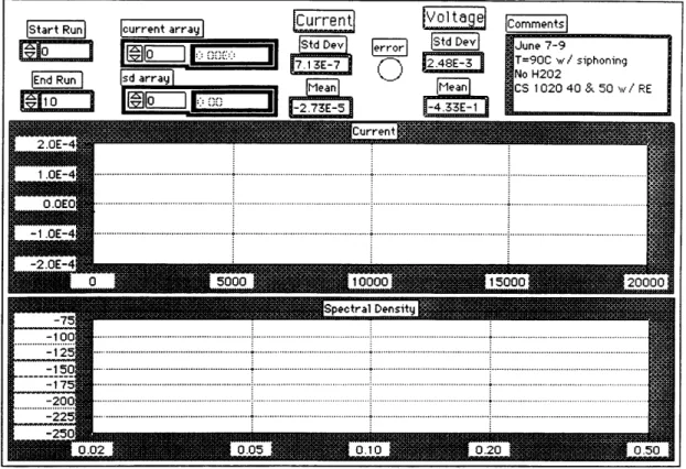
2.5.3 LabVIEW ... ...39
2.5.3.1 Design and Capabilities ...41
2.5.3.2 Voltage & Current Data Acquisition & Analysis...41
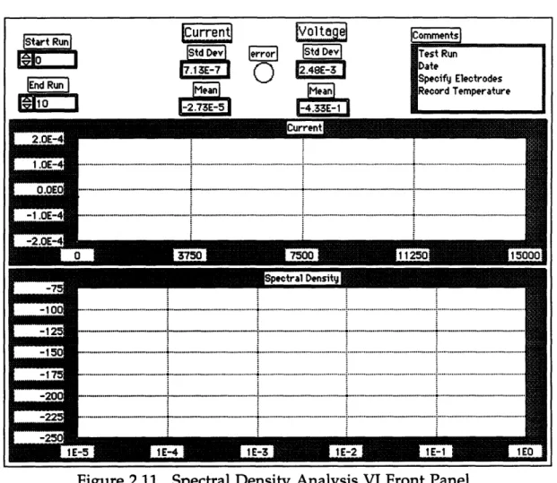
2.5.3.3 Spectral Density Analysis ...43
2.6 Experimental Procedures ... 45 3 Results ... 46 3.1 Temperature Comparisons ... 46 3.1.1 Experimental Parameters ... 46 3.1.2 Pitting Analysis ... 46 3.1.3 Current Analysis ... 47 3.2 Radiation Comparisons ... 49 3.2.1 Experimental Parameters ... 49 3.2.2 Pitting Analysis ... 50 3.2.3 Current Analysis ... 50
3.3 Simulated Radiation Comparisons ...50
3.3.1 Experimental Parameters ... 50
3.3.2 Pitting Analysis ... 53
3.3.3 Current Analysis ... 53
3.4 Different Metals Comparisons ... 54
3.4.1 Experimental Parameters ... 54 3.4.2 Pitting Analysis ... 54 3.4.3 Current Analysis ... 54 3.5 Loading Geometry ... 56 4 Discussion of Results ... 59 4.1 Temperature Comparisons ... 59 4.2 Radiation Comparisons ... 61
4.3 Simulated Irradiation Comparisons ...62
4.4 Different Metals Comparisons ... 65
4.5 Conclusions of Analysis Results ... 67
5 Conclusions ... 68
5.1 Method as a Predictive Tool ... 68
5.2 Experimental Apparatus . ...68
5.3 Analysis Techniques ... 69
6 Future Work ... 70
Appendix A ... 75 Appendix B ... 94 Appendix C ... 104
LIST OF FIGURES
1.1 Groundwater Behavior Near Waste Package ...15
1.2 Pitting Factor as a Function of Pit Depth and Uniform Attack ...22
1.3 Passive-Active Cell ... 22
2.1 Inner Can Components ... 31
2.2 Inner Can Internals ... 32
2.3 Outer Can Components ... 34
2.4 Spent Fuel Pool Configuration ... 36
2.5 Radial Dose Distribution in SFP ... 37
2.6 Carbon Steel Electrode Before Test ... 40
2.7 Carbon Steel Electrode After Test ... 40
2.8 Data Acquisition VI Front Panel ... 42
2.9 Data Acquisition VI Block Diagram ... 42
2.10 Data Acquisition VI Hierarchy ... 43
2.11 Spectral Density Analysis VI Front Panel ...44
3.1 Current Data for Temperature Comparisons ...48
3.2 Power Spectrums for Temperature Comparisons ...48
3.3 Hydrogen Peroxide Concentration Buildup in the SFP ...49
3.4 Titanium Electrode Before Testing ... 51
3.5 Titanium Electrode After Testing ... 51
3.6 Current Data for Radiation Comparisons ...52
3.7 Power Spectrums for Radiation Comparisons ...52
3.8 Current Data for Simulated Irradiation Comparisons ...55
3.9 Power Spectrums for Simulated Irradiation Comparisons ...55
3.10 Current Data for Different Metals Comparisons ...57
3.11 Power Spectrums for Different Metals Comparisons ...57
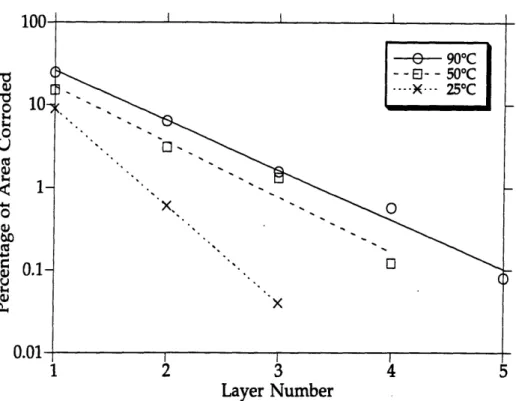
4.1 Corroded Area for Temperature Comparison Electrodes ...60
4.2 Corroded Volume for Temperature Comparison Electrodes ...60
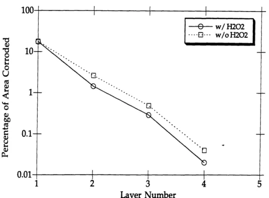
4.3 Corroded Area for Simulated Irradiation Comparison Electrodes ...63
4.4 Corroded Volume for Simulated Irradiation Comparison Electrodes ...63
4.5 Corroded Area for Different Metals Comparison Electrodes ...66
4.6 Corroded Volume for Different Metals Comparison Electrodes ...66
A.1 Front Panel for Voltmeter Initialization VI ...76
A.2 Block Diagram Sequence 1 for Voltmeter Initialization VI ... 77
A.4 Block Diagram Sequence 3 for Voltmeter Initialization VI ... 78
A.5 Block Diagram Sequence 4 for Voltmeter Initialization VI ... 78
A.6 Front Panel for Voltage Operation VI ... 80
A.7 Block Diagram Sequence 1 for Voltage Operation VI ... 80
A.8 Block Diagram Sequence 2 for Voltage Operation VI ... 81
A.9 Block Diagram Sequence 3 for Voltage Operation VI ... 81
A.10 Block Diagram Sequence 4 for Voltage Operation VI ... 82
A.11 Block Diagram Sequence 5 for Voltage Operation VI ...82
A.12 Block Diagram Sequence 6 for Voltage Operation VI ...83
A.13 Block Diagram Sequence 7 for Voltage Operation VI ...83
A.14 Front Panel for Picoammeter Operation VI ... 85
A.15 Block Diagram Sequence 1 for Picoammeter Operation VI ... 86
A.16 Block Diagram Sequence 2 for Picoammeter Operation VI ... 86
A.17 Block Diagram Sequence 3 for Picoammeter Operation VI ...87
A.18 Block Diagram Sequence 4 for Picoammeter Operation VI ...87
A.19 Front Panel for Data Acquisition VI ... 88
A.20 Block Diagram for Data Acquisition VI ... 89
A.21 Front Panel for Data Analysis VI ... 91
A.22 Block Diagram for Data Analysis VI ... 91
A.23 Front Panel for Data Transfer VI ... 93
A.24 Block Diagram for Data Transfer VI ... 93
B.1 Layer #1 (Top Layer) for 90°C Carbon Steel Electrode ... 95
B.2 Layer #2 for 90°C Carbon Steel Electrode ... 95
B.3 Layer #3 for 90°C Carbon Steel Electrode ... 96
B.4 Layer #4 for 90°C Carbon Steel Electrode ... 96
B.5 Layer #5 (Bottom Layer) for 90°C Carbon Steel Electrode ...97
B.6 Layer #1 (Top Layer) for 50°C Carbon Steel Electrode ... 97
B.7 Layer #2 for 50°C Carbon Steel Electrode ... 98
B.8 Layer #3 for 50°C Carbon Steel Electrode ... 98
B.9 Layer #4 (Bottom Layer) for 50°C Carbon Steel Electrode ...99
B.10 Layer #1 (Top Layer) for 25°C Carbon Steel Electrode ... 99
B.11 Layer #2 for 25°C Carbon Steel Electrode .... 100
B.12 Layer #3 (Bottom Layer) for 25°C Carbon Steel Electrode ... 100
B.13 Layer #1 for Simulated Irradiation Test with H202 Added ... 101
B.14 Layer #2 for Simulated Irradiation Test without H202 Added ... 101
B.16 Layer #2 for Cast Iron Electrode ... 102
B.17 Layer #3 (Bottom Layer) for Cast Iron Electrode ... 103
C.1 Corroded Surface Representation of 90°C Test Electrode ... 105
C.2 Corroded Surface Representation of 50°C Test Electrode ...106
C.3 Corroded Surface Representation of 25°C Test Electrode ...107
C.4 Corroded Surface Representation of Simulated Irradiation Test with H202 Added ... 108
C.5 Corroded Surface Representation of Simulated Irradiation Test without H202 Added ... 109
LIST OF TABLES
1.1 Decay Power from Fission Products and Actinides ...13
2.1 Representative Gray Cast Iron Data ... 28
2.2 Representative Carbon Steel 1018 Properties ... 28
2.3 Carbon Steel 1020 Impurities for Sample A302B ... 28
2.4 Inconel 825 Analysis Results for Sample HH6756FG ...29
2.5 Titanium Code-12 Material Tests for Sample T-0300 ... 29
2.6 Composition of J-13 Well Water ... 35
2.7 Spent Fuel Elements Data as of 1-1-94 ... 37
3.1 Corrosion Data for Temperature Comparison Electrodes ...47
3.2 Current Analysis for Temperature Comparison Runs ...49
3.3 Current Analysis for Radiation Comparison Runs ...50
3.4 Corrosion Data for Simulated Radiation Comparison Electrodes ...53
3.5 Current Analysis for Simulated Radiation Comparison Runs ...53
3.6 Corrosion Data for Different Metals Comparison Electrodes ...54
3.7 Current Analysis for Different Metals Comparison Runs ...56
3.8 Loading Data for Temperature Comparison Runs ... 56
3.9 Loading Data for Radiation Comparison Runs ...56
3.10 Loading Data for Simulated Radiation Comparison Runs ...58
3.11 Loading Data for Different Metals Comparison Runs ...58
4.1 Analysis Results for Temperature Comparison Electrodes ...61
4.2 Fifth Order Polynomial Curve Fit Coefficients ...61
4.3 Slope Values for Logarithmic Curve Fit . ... 61
4.4 Fifth Order Polynomial Curve Fit Coefficients ...62
4.5 Slope Values for Logarithmic Curve Fit . ... 62
4.6 Analysis Results for Simulated Radiation Comparison Electrodes ...64
4.7 Fifth Order Polynomial Curve Fit Coefficients ...64
4.8 Slope Values for Logarithmic Curve Fit . ... 64
4.9 Analysis Results for Simulated Radiation Comparison Electrodes ...65
4.10 Fifth Order Polynomial Curve Fit Coefficients . ...67
1 Background
Permanent disposal of high level nuclear waste is an unresolved issue in the United States. The waste, mainly spent fuel from nuclear power plants and liquid waste from defense reprocessing operations, is currently stored at power plants or in large tanks at defense facilities. However, these sites are only a temporary solution until a final resting place is available. The current plan in the United States is to store the spent fuel in metal containers within a deep geological mined cavity. Liquid waste from defense operations will be solidified in glass and stored in the same mined cavity. All these wastes will need a primary release barrier, the canister, which is the subject of this thesis.
High temperature and radiation effects associated with high level
nuclear waste, specifically spent fuel, are discussed in Section 1.1. Section 1.2 describes high level nuclear waste canisters including the current design and the metals under consideration. General corrosion of the canisters and non-uniform corrosion as pitting is discussed in Section 1.3. Section 1.3 also provides information on previous applications of electrochemical analysis. The purpose and goals of this project are noted in Section 1.4.
1.1 High Level Waste
The currently proposed design for the geological repository at Yucca
Mountain would dispose of spent fuel from both boiling water reactors
(BWR) and pressurized water reactors (PWR) in metal canisters. These spent fuel elements are sources of intense radiation and heat since they contain an assortment of fission products and actinides created during reactor operation. Beta and gamma rays contribute most of the heat through energy deposition in the fuel and immediate surroundings, while only gamma rays are a factor
in dose outside the canister. Fission products dominate the radioactivity and decay heat for the first 150 years after discharge from the reactor, and then the actinides become relatively more significant. Table 1.1 lists the decay power and activity at discharge of the significant fission products and actinides for a 1000 MWe PWR with 33 MWD/kg burnup. Radionuclides that decay in the first ten years after discharge or have half-lives greater than 100,000 years (except for Tc-99, 1-129 and U-234) are excluded.1
1Benedict, M., T.H. Pigford and H.W. Levi, Nuclear Chemical Engineering. 2nd Edition,
Table 1.1. Decay Power from Fission Products and Actinides
Radionuclide
*H-3 *Kr-85 Sr-90 Nb-93m Tc-99 Cd-113m Sb-125 *I-129 Cs-134 Cs-137 Pm-147 Sm-151 Eu-152 Eu-154 U-234 Pu-236 Pu-238 Pu-239 Pu-240 Pu-241 Am-241 Am-242m Am-243 Cm-243 Cm-244 Cm-245 Cm-246 Half-life yr 12.4 10.8 27.7 13.6 2.1E6 13.6 2.71 1.7E7 2.05 30.0 4.4 87 12.7 16 2.5E5 2.85 86 2.4E4 6580 13.2 458 152 7950 32 17.6 9300 5500* volatile fission product
Activity
Ci/yr
1.9E4 3.1E5 2.1E6 3.95 390 286 2.4E5 1.01 6.7E6 2.9E6 2.8E6 3.4E4 341 1.9E5 19.4 134 1.OE5 8.8E3 1.3E4 2.8E6 4.5E3 116 477 90.3 7.4E4 9.8 1.9 Decay PowerW/yr
0.64 503 2751 0.04 0.26 0.38 798 0.001 7.1E4 4744 1444 6.05 2.57 1560 0.56 4.66 3314 273 405 116 150 0.05 15.4 3.29 2589 0.33 0.06 Decay Modef- /-
1-
P-f-,
/3-
f-/3-,-,EC
P-a
a
a
a
a,
-a
a, IT
a
a, EC
a
a
a
cx cx1.1.1 Temperature
After the first 150 years in the repository, most of the fission product decay heat contribution is gone. Long-lived actinides are still producing
significant heat though, mainly Am-241 and several of the plutonium
isotopes. Even though only a small fraction of the initial decay power
remains, this heat must be considered in repository loading considerations
and spent fuel storage unit designs. Spent fuel entering the repository is expected to have a thermal output of 1.3 to 3.3 kW per container. The temperature histories of the waste packages are a function of the thermal properties of the near-field rock, specific configuration of repository boreholes and emplacement drifts, heat transfer mode and container output power.
Assessments of these parameters for a hot repository predict that the temperature at the container wall will remain above 100°C for at least 300 years after placing the package in the repository.2 Since the temperatures are predicted to be above the boiling point, liquid water would also be predicted to be excluded from the near-field repository environment for several hundred years; however, water may be present in rock pores as a liquid up to 140°C.3
One consequence of the elevated temperature in the repository will be boiling of the groundwater in the host rock near the waste package, resulting in changes in the concentrations of silicon, aluminum, magnesium, calcium, etc. Figure 1.1 shows the drying zones around the waste package from waste heat. Water vapor from boiling does not readily move in the matrix. If there is a fracture nearby, the vapor moves to the fracture, where it is forced away from the waste package by higher gas pressure in the boiling zone caused by vapor production. Heat-pipe effects may occur and keep the area around the waste package near the boiling isotherm because of two-phase refluxing in the fractures. Vapor may also be driven outward through fractures and refluxing to the waste package could then occur in the matrix.
Waste packages may also be contacted by water during times of episodic liquid water movement through the repository. The possibility of episodic fracture flow has been recognized for several reasons: precipitation depends 2Beavers, J.A., N.G. Thompson and C.L. Durr, Pitting, Galvanic, and Long-Term Corrosion
Studies on Candidate Container Alloys for the Tuff Repository, Cortest Columbus Technologies
for U.S. Nuclear Regulatory Commission, NUREG/CR-5709 (1992).
3Beavers, J.A. and C.L. Durr, Immersion Studies on Candidate Container Alloys for the Tlff
Repository, Cortest Columbus Technologies for U.S. Nuclear Regulatory Commission,
strongly on surface topography rather than falling uniformly, subsurface
infiltration is higher in high-permeability pathways such as fractures, and
precipitation is infrequent but occurs in short intense thunderstorms.
Episodic fracture flow has important implications for aqueous transport. In fracture-dominated flow, the concentration field of a species depends on the geometric properties of the fracture network. Sorption onto fracture surfaces retards the movement of species under fracture-dominated flow. As a result,
the geochemistry of water reaching the waste packages through episodic
events will be different from water extracted in the matrix.4
Welded Tuff in Unsaturated Zone
Figure 1.1. Groundwater Behavior Near Waste Package
4Nitao, J.J., T.A. Buscheck and D.A. Chesnut, "Implications of Episodic Nonequilibrium
Fracture-Matrix Flow on Repository Performance," Nuclear Technology, 104, 385 (1993).
III
I IIII
I IIIII II I
III
III
III
I IIII
III
III
III
III
I IIII
I , I IIII
Irl IIIIII I III I I I II I I I I I IIIIII IIIIII III I III I IIIIII I I I I II III I I III III I IIIIII, I I I I III IIII I I I I I IIIIII III I I III I I ,II I 1 II I I I III1 I III I I IIIIII I I II , III IIIIII I III I I I II I I I I IIII I IIII 1-1 I I I I II I I I I I 1 I II I IIII I I I III1 I I I III I I I III, r r I I I II I III I 1 I I I III I I I III I IIIIII III I I I. I I II1.1.2 Radiation Effects
After the first 150 years, some of the radionuclides still have a
relatively high activity.
The effects of this long-term, low dose rate
irradiation in combination with the high temperature and aggressive
chemical environment on the waste canister must be carefully considered to ensure that the barrier is not breached before at least 300 years.
The influence of a radiation field on a repository has received relatively little attention, although the research done on the effects for water and dilute aqueous systems is much more extensive. The highest levels of radiation are present when the waste is emplaced, after which the radiation levels continue to decay. The radiation of most interest concerning container
corrosion effects is gamma radiation, but fortunately most fission products
resulting in gamma decay have relatively short half-lives. The long-lived actinides are predominantly alpha emitters, so their radioactive contribution
is unimportant for container performance. Since alpha and beta particles
cannot penetrate the primary barrier while it is still intact, these particles are not of major concern until the waste container is breached.
In terms of the high early gamma radiation fields, radiolysis, or the chemical breakdown of water by radiation, is the process of most concern.
Photon radiations deposit energy to the medium through which they are
passing by photoelectric compton scattering and pair production with the
electrons of the medium. The primary interactions release secondary
electrons that lose energy through the same physical mechanisms. The result is a cascade of electrons and secondary photons that excite and ionize the medium. In aqueous solutions, the deposited energy goes into the excitation and ionization of water molecules that decompose into a host of chemical species. Some of the most common radiolysis reactions are given below:
H20-> H20+ H20-> e-H20 -> H20*
H20
++ H
20-> H
30
++ OH
2HO2-> H202 + 02 20H -> H202OH
+ H202-> H20 + HO2Amounts of the above species that are produced depends upon the ionization
radiation.5 The major radical reactions principally form molecular hydrogen, hydrogen peroxide, or reform water. Any water that enters the repository must be assumed to flow by the canisters. This is important because the H202
that would be formed by radiolysis is known to change the oxidation potential of most aqueous solutions and thus may change the expected corrosion rate and mechanisms of the canister metal (albeit in a favorable direction in some cases).6
Irradiation of pure water in a closed system by low LET (linear energy transfer) particles results in a steady state with low solution concentrations of hydrogen, oxygen and hydrogen peroxide. With high LET radiation, a steady state condition is never reached or only after a long period of time. An open
system leads to steady state concentrations of hydrogen peroxide with
continual escape of hydrogen and oxygen; essentially, the radiation
decomposes water into hydrogen and oxygen. In the presence of oxygen, hydrogen peroxide is the main radiolysis product of water7. For moist air
systems, radiolysis products are predominantly NO, N
20 and 03 for
temperatures above 135°C. From 120 to 135°C, NO2, N204, H20 and 03 are the
main products; and below 120°C, HNO2 and H20 are predominant. In liquid
water at high radiation levels, small amounts of nitrates and nitrites will also be produced. 8 Nitrous oxides dissolve in water to form nitric acid under
certain conditions (two-phase).
For the repository, the combination of liquid water and radiation is only possible during periods of liquid water movement through it. The J-13 well water from Yucca Mountain was analyzed in 1985 by Glass, and its primary reaction with radiation was to produce the oxidizing species 02 and H202 with small concentrations of 02- and HO2.2 In summary, gamma
radiation with water or dilute aqueous solutions produces a host of transient radicals, ions and stable molecular species. Other species are also generated by reactions with components of the groundwater.
5Simonson, S.A., Modeling of Radiation Effects on Nuclear Waste Package Materials. Ph.D.
Thesis, Massachusetts Institute of Technology, Cambridge, MA (1988).
6Uhlig, H.H. and R.W. Revie, Corrosion and Corrosion Control. John Wiley & Sons, New York
(1985).
7Spinks, J.W.T. and R.J. Woods, Introduction to Radiation Chemistry. 3rd Edition, John Wiley
& Sons, New York (1990).
8
Van Konynenburg, R.A., Radiation Chemical Effects in Experiments to Study the Reaction of
Glass in a Gamma Irradiated Air, Groundwater, and Tuff Environment, Lawrence Livermore
1.2 High Level Waste Canister
Having discussed some of the temperature effects and design
constraints as well as the radiation sources and resulting chemical changes in the environment surrounding the waste canister, the next step is to specify the canister configuration and design parameters.
1.2.1 Current Design and Expectations
Sealed canisters will hold high level waste during handling,
transportation, and storage phases of disposal. The current design is a
multi-purpose canister (MPC) holding spent nuclear fuel assemblies and
surrounded by a storage unit, transportation cask, or disposal container.
Several MPC designs are under consideration - a legal weight truck cask for four pressurized water reactor (PWR) or nine boiling water reactor (BWR) assemblies, a medium-sized rail cask for 12 PWR or 24 BWR assemblies, and a large-sized rail MPC for 21 PWR or 40 BWR assemblies. Different designs are needed to accommodate the limitations of various reactor facilities. MPC's consist of a cylindrical shell to provide structural support and geometrical stability, two lids to form containment boundaries, a spent fuel basket to
support the SNF and provide a mechanism for heat transfer, and a shield
plug to keep dose rates as low as reasonably achievable.9
1.2.2 Candidate Metals
The metals under consideration for the canisters are cast iron, carbon steel, Inconel 825, and titanium grade-12. Stainless steel was proposed as a suitable container material but it has been eliminated because of uncertainty in non-uniform corrosion resistance under repository conditions.
1.2.2.1 Iron and Low Carbon Steel
The general corrosion of irons and carbon steels not subjected to
radiation is controlled by the buildup of corrosion product films; however, with 1.5 Gy/hr the corrosion rate becomes 15 times higher in water. This is
90CRWM Bulletin Special Edition, "MPC Conceptual Design Report Submitted to OCRWM,"
thought to be caused not only by the production of oxidizing species but also by a radiation-induced change in film morphology and protectiveness.'0
1.2.2.2 Inconel
Inconel is generally very resistant to pitting, and pits that do occur are shallow rather than deep. Inconel also resists attack by oxidizing aqueous
media so it is used extensively where oxidation resistance at elevated
temperatures is required. In order for Inconel to become susceptible to stress corrosion cracking, specifically damaging elements such as phosphorus or
boron must reach a critical concentration by slow diffusion to grain
boundaries; so to minimize cracking, control of the Inconel composition is
most important.
61.2.2.3 Titanium Alloys
The potential failure mechanisms for titanium are crevice corrosion and hydrogen-induced cracking. Both grades 2 and 12 have been studied but grade 12 has been found to be more crevice corrosion resistant.1 1 The propagation of crevice corrosion on grade 2 materials depend on temperature
and oxygen concentration; after the oxygen is consumed, the material
repassivates. For grade 12 titanium, crevice corrosion propagation is almost independent of temperature and repassivates for temperatures less than 73°C even in the presence of excess oxygen.12
Overall, the effect of radiation on localized corrosion appears to be specific to individual materials.
1.3 Corrosion
In determining lifetime estimates for the canisters, it is important to
understand the mode of attack. The metals under consideration have
different susceptibility to general corrosion and non-uniform corrosion, and 10Shoesmith, D.W., B.M. Ikeda and F. King, Effect of Radiation on the Corrosion of Candidate
Materials for Nuclear Waste Containers, AECL Research, Whiteshell Laboratories, Pinawa,
Manitoba (1993).
11Johnson, L.H., D.W. Shoesmith, B.M. Ikeda and F. King, Lifetimes of Titanium and Copper
Containers for the Disposal of Used Nuclear Fuel, AECL Research, Whiteshell Laboratories,
Pinawa, Manitoba (1991).
1 2Ikeda, B.M., M.G. Bailey, M.J. Quinn and D.W. Shoesmith, The Development of an
Experimental Data Base for the Lifetime Predictions of Nuclear Waste Containers,
"Application of Accelerated Corrosion Tests to Service Life Prediction of Materials," G. Cragnolino and N. Sridhar, Eds., American Society for Testing and Materials (1993).
it is also necessary to consider the environment around them. Pitting and stress corrosion cracking are discussed here because they are the most likely mechanisms of failure for the candidate metals. To study corrosion, various electrochemical techniques are often used. Since non-uniform corrosion is
composed of random events, an electrochemical noise technique was
investigated for its suitability as an analysis tool.
1.3.1 General Corrosion
Rusting of iron and tarnishing of silver are common examples of
uniform corrosion, which is characterized by a constant corrosion depth or weight loss per unit area across a surface. The rate of attack representing
time-averaged values is usually shown in mm/y (millimeters per year) or
gmd (grams per square meter per day) referring to metal penetration or
weight loss of metal, not including any corrosion products on the surface. The initial corrosion rate will generally be greater than the subsequent rate; therefore the duration of exposure is an important parameter, and it is often not safe to extrapolate short experimental times.13
Three classifications are commonly used as a rough guideline for uniform corrosion acceptability. A material with a rate less than 0.15 mm/y is considered to have good corrosion resistance and can be used for critical components. Rates from 0.15 to 1.5 mm/y are sometimes satisfactory for
non-critical parts where more corrosion is tolerable. Materials with uniform
corrosion rates greater than 1.5 mm/y are generally considered
unsatisfactory.6
For the prospective Yucca Mountain repository, the rate is very
important because the canisters must last a minimum of 300 years and would preferably withstand penetration for 1000 years or longer. Generally, the maximum acceptable rate is found by dividing the canister wall thickness by the canister lifetime and the safety factor. For example, a 10 cm thick titanium canister expected to maintain integrity for 1000 years with a safety factor of 2.0 would have a maximum corrosion rate of 0.05 mm/yr, which must be supported experimentally to be accepted as a reasonably achievable corrosion rate in the environment expected in the repository. Canister design will consequently differ for each metal under consideration if each is to
achieve comparable lifetimes, since they will surely have varying corrosion rates. For some confidence in short term experimental results, the corrosion mechanism must also be carefully studied since 1000 year tests are impractical.
1.3.2 Non-uniform Corrosion
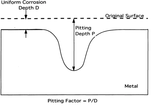
One localized type of corrosion is pitting, which is characterized by varying rates of attack over the surface. Corrosion in a small fixed area acting as an anode results in deep pits, while larger areas produce shallow pits.
Pitting factor, illustrated in Figure 1.2, refers to the depth of pitting measured
by the ratio of deepest to average metal penetration as determined by the sample's weight loss. Uniform attack results in a pitting factor of unity.
For pitting to occur on a passive surface, the corrosion potential must
be greater than a critical potential. Increasing the fraction of alloyed
chromium, nickel, molybdenum and rhenium in stainless steels shifts the critical potential and increases the resistance to pitting. When pitting does occur, a passive-active cell is created as seen in Figure 1.3. This produces a high current density and a high corrosion rate at the pit; meanwhile, the
surrounding surface is polarized to potentials below the critical value.
Chloride ions, if present, would enter the pit concentrate and produce an acid solution. A high Cl- concentration and low pH environment keep the pit active, while the high specific gravity of the corrosion products causes leakage out of the pit; breakdown of the passive layer occurs where the metal surface is contacted. When the pit surface is repassivated, pitting stops. Dissolved oxygen or passivator ions are needed, but successful repassivation depends on pit geometry and flow rate of the surrounding solution.
Several methods are commonly used to reduce or avoid pitting.
Cathodic protection at a potential below the critical value can be accomplished by using an applied current or coupling in a conductive medium to a greater area of zinc, iron or aluminum. Additional anions such as OH- or N03- can be added to chloride environments, or the oxygen concentration can be reduced. Temperature can be adjusted to discourage pitting corrosion. For
example, the lowest possible operating temperature should be used for
stainless steel type 304. In an aerated 4% NaCl solution, this metal
experiences maximum weight loss by pitting at 900C.14
1 4
Uniform Corrosion
Depth D
Oriqinal Surface
Pitting Factor = P/D
Figure 1.2. Pitting Factor as a Function of Pit Depth and Uniform Attack6
NaCI Environment
Oxygen Sites
In the repository, there are several chemical factors that may contribute to or alleviate pitting attack of the canisters such as anion concentration,
radiation and pH. Since water contacting the canisters is expected to
evaporate and rise potentially to condense and flow into the repository again, the concentration of anions near the canisters would be expected to increase due to this evaporation effect. After the temperature drops below the boiling point, water near the canisters will dissolve these additional anions; and this water could be highly corrosive and thus enhance pitting. Although pitting is not directly caused by radiation, a pit that has already been initiated may have an increased propagation rate because the water inside the pit may have a higher concentration of H202 since the innermost point of the pit is closer to
the radiation source and has a slightly higher gamma flux, thus causing a differential electrochemical condition.
The effect of pH on the corrosion rate depends on the metal under consideration. For aluminum and zinc, the corrosion rate increases at both high and low pH; but for iron and steel, the penetration rate actually decreases above a pH of about 10.
1.3.3 Electrochemical Analysis
Electrochemistry is the study of the chemical response of a system to an electrical stimulation. When a metal is immersed in a given solution, electron exchange reactions occur at the surface of the metal causing it to
corrode.
Since this involves electrochemical oxidation and reduction
reactions, it is useful to study and measure the corroding systems with
electrochemical methods. The technique explained in this thesis used three electrodes - two working electrodes and a reference electrode. The working electrode is the electrochemical term for the specimen where the reactions of interest take place. The reference electrode is a stable half-cell against which the potential of the working electrode is measured. In an electrochemical
experiment, four parameters are of interest - potential, current, charge and
time. Different combinations of these parameters and electrode types create a long list of possible techniques, including voltammetry, polarography, cyclic
voltammetry, chronoamperometry, chronopotentiometry and more.
1 5Electrochemical noise techniques are unique because they provide an entirely
1 5A Review of Techniques for Electrochemical Analysis, Electrochemical Instruments Group,
passive analysis tool. No current or voltage is applied to the system under test.
Electrochemical noise techniques have become widely used in various
applications. Stewart et. al. used current pulses to detect the initiation,
temporary propagation and repassivation of intergranular stress corrosion
cracks in sensitized stainless steel under BWR conditions.16 For a totally random current signal (as is true for pitting), impedance techniques have not been found to be successful, and only analysis of the current fluctuations will produce information of the processes involved. Gabrielli and Keddam used
this sort of electrochemical noise analysis to study active and inhibited
corrosion of iron, aluminum alloys and stainless steel.17 Blanc measured electrochemical noise by a cross correlation method in studying 1/f noise or
flicker noise.1 8 Noise signals can also give information about the magnitude and decay time of electrode processes such as the onset of pitting or the effect
of corrosion inhibitors.
Bertocci measured electrochemical noise and
separated the deterministic response from random current fluctuations when examining aluminum at and below the pitting potential. 19 Bertocci and Kruger also analyzed the difference in noise levels for amorphous and
crystalline Fe-Cr-Ni alloys, and they showed that the breakdown of the
passive film was different for the two forms.2 0 Hladky and Dawson measured
corrosion with electrochemical 1/f noise, and they found a correlation
between the rate and mode of corrosion attack and fluctuations of the
corrosion potential. They predicted the possibility of detecting pitting and
crevice attack based on non-perturbative electrochemical monitoring.2 1
16Stewart, J. et. al., "Electrochemical Noise Measurements of Stress Corrosion Cracking of Sensitized Austenitic Stainless Steel in High-Purity Oxygenated Water at 2880C," Corrosion Science, 33, 73 (1992).
17Gabrielli, C. and M. Keddam, "Review of Applications of Impedance and Noise Analysis to Uniform and Localized Corrosion", Corrosion, 48, 794 (1992).
18Blanc, G., C. Gabrielli and M. Keddam, "Measurement of the Electrochemical Noise by a Cross Correlation Method", Electochimica Acta, 20, 687 (1975).
19Bertocci, Ugo, "Separation Between Deterministic Response and Random Fluctuations by Means of the Cross-Power Spectrum in the Study of Electrochemical Noise," J. Electrochem. Soc., 128, 520 (1981).
2 0Bertocci, Ugo and J. Kruger, "Studies of Passive Film Breakdown by Detection and Analysis of
Electrochemical Noise," Surface Science, 101, 608 (1980).
2 1Hladky, K. and J.L. Dawson, "The Measurement of Corrosion Using Electrochemical 1/f
1.4 Project Purpose and Goals
This project was designed to evaluate passive electrochemical noise techniques for measuring pitting and corrosion characteristics of candidate materials under prototypical repository conditions. Experimental techniques
were also developed and optimized for measurements in a radiation
environment. The specific associated goals include:
* designing an appropriate experimental test apparatus, * replicating the radiation level, chemical environment, and
temperature for a cold repository scenario, * determining the effects of temperature on pitting and
electrochemical noise data,
* determining the effects of radiation on pitting and electrochemical noise data,
* determining the validity of simulated irradiation testing, * comparing data and trends for different metals,
* critiquing the analysis techniques for use in passive monitoring applications,
2 Experimental Components
2.1 Overview
An experimental apparatus was designed and built to make
electrochemical noise measurements with and without the presence of a
gamma radiation field. The experimental assembly consisted of a reference
electrode, a working electrode and a counter electrode.
To use
electrochemical noise techniques for analysis, the current was measured across the working and counter electrodes, and the voltage was measured across the reference and counter electrodes.
The working, or test electrode, was made of one of the candidate materials described in Section 2.2.1., and the counter electrode was an Inconel 825 specimen. The reference electrode was a glass-body, sealed, single-junction Ag/AgC1 electrode with a gel filling for use up to 1200C. Electrode preparation was accomplished by initial surface sanding, and it was then set in an epoxy insulator to protect the soldering point and to prevent the electrodes from touching each other during operation. After final sanding, the surface was photographed. All three electrodes were situated inside a
stainless steel can through which water typical of that found at Yucca
Mountain was slowly pumped.
Gamma radiation results in the decomposition of H
20 and the
formation of the primary long-lived oxidizing species H202. To monitor the
buildup of H
20
2in the experiment, measurements were made
out-of-assembly using ampoules for photometric analysis of hydrogen peroxide.
Water temperature was maintained by a proportional integral derivative
(PID) temperature controller with a thermocouple adjacent to the electrodes and a flexible fiberglass heating tape around the outside of the assembly. A pressure transducer was located on the outlet water line to monitor any pressurization of the assembly for safety purposes. This entire setup fit within an outer aluminum can which was sealed and then inserted into the gamma radiation field in the MITR II spent fuel pool. Tests were conducted, and all data was sent to the data acquisition program, LabVIEW 2, for storage and analysis.
The electrodes used in this experiment are discussed in Section 2.2. This includes a description of the candidate metals studied and the surface preparation procedure developed for them. Section 2.3 discusses the main
structural units of the experimental assembly which are the stainless steel inner can and the aluminum outer can. The external apparatus is described in Section 2.4 including discussion of the synthetic water production, gamma
radiation source and dose measurements, temperature control system, and
pressure monitoring for safety purposes.
Section 2.5 describes data
acquisition. Microscopy was used to compare surface defects, and LabVIEW 2 was used to store and analyze the electrochemical noise measurements. The design and capabilities of LabVIEW 2 are discussed, and the methods of data acquisition and analysis are described. Section 2.6 puts the whole picture
together and describes the experimental procedures, drawing on the
descriptions in the previous sections.
2.2 Electrodes
The Yucca Mountain Site Characterization Project has selected
potentially suitable metals for use in fabrication of the high level waste storage canisters. Currently, these metals are cast iron, carbon steel 1018 or 1020, Inconel 825 and titanium code-12. Tables 2.1-5 give more information on these metals' chemical and physical properties.
2.2.1 Candidate Metals
Gray cast iron is easy to cast sound and readily machinable. It is not usually considered weldable and is incapable of cold forming.2 2 Cast iron remains an option despite its rapid corrosion rate because it has been widely used for many years and therefore has more long-term data available to better assist in making 300 year canister performance predictions defensible. Cast
iron samples for our project were donated by the Charlotte Brothers Iron
Foundry, Inc. of Blackstone, MA as 3/8" plate. Table 2.1 shows representative properties for SAE Grade G3500 and ASTM Class 35 gray cast iron.2 3
Carbon steel also has relatively less favorable corrosion behavior but many years of experience. Table 2.2 shows composition limits for the sample of 1/2" 1018 carbon steel rod and generic physical properties for carbon steel.22
Impurities in our 3/8" 1020 carbon steel plate sample are shown in Table 2.3.
22Carmichael, C. Editor, Kent's Mechanical Engineers' Handbook. 12th Edition, "Design and
Production Volume," John Wiley & Sons, New York (1956).
23ASM Metals Reference Book, 2nd Edition, American Society for Metals, Metals Park, Ohio
Inconels as a general class of materials are relatively new compared to carbon steel and cast iron, but have excellent corrosion resistance and would probably not fail by general corrosion. Non-uniform modes of attack, such as stress corrosion cracking, are of greater concern for Inconels. The chemical
analysis and physical properties for the 1/2" Inconel 825 rod used in this
experiment are in Table 2.4.
Titanium is exceptionally resistant to general corrosion but it is also a relatively new material, and it is much more difficult to weld and machine than any of the iron or nickel-based alloys. Material tests for the 1/8" titanium grade-12 plate used in this experiment are in Table 2.5.
Table 2.1. Representative Gray Cast Iron Data Composition Limits (%)
SAE Grade TC Mn Si P S
G3500 3.0- 3.3 0.6- 0.9 2.2- 1.8 0.08 0.16 Mechanical Properties
Tensile
Torsional Compressive
Reversed Hardness
Strength
Shear
Strength
Bending
(HRB)
ASTM (MPa) Strength (MPa) Fatigue
Class (MPa) (MPa)
35 252 334 855 110 212
Table 2.2. Representative Carbon Steel 1018 Properties Composition Ranges (%)
SAE # C Mn P S
1018 0.15 - 0.20 0.6 -0.9 0.04 0.05
Physical Properties
Yield Strength
Tensile Strength
Elongation
50,000 psi . 70,000 psi
I
21%Table 2.3. Carbon Steel 1020 Impurities for Sample A302B
C Mn P S Si Mo
Actual % 0.21 1.24 0.011 0.015 0.22 0.55
Table 2.4. Inconel 825 Analysis Results for Sample HH6756FG Chemical Analysis
C Mn P Si Ni Cr Cu Mo Ti Cb Sn Fe Al
e 0.01 0.34 0.001 0.10 43.9 21.86 2.05 2.72 0.86 28.07 0.09 Physical Properties
Yield Strength Tensile Strength Elongation
54,000 ksi 105,000 ksi 42 %
Table 2.5. Titanium Code-12 Material Tests for Sample T-0300 Chemical Analysis
C Fe N Mo H O Ni
/ o 0.(18 0.11 0.004 0.29 0.005 0.13 0.82 Mechanical Tests
Yield-L Yield-T Tensile-L Tensile-T Elong.-L Elong.-T
62 ksi 83ksi si 87 ksi 96 ksi 22 % 20 %
: L indicates longitudinal orientation and T indicates transverse orientation
2.2.2 Sample Preparation
Plates and rods of the candidate materials were cut into 1 cm squares or circles depending on the shape of the initial sample, and a 1/16" hole was drilled into one side. An identification number was stamped on the back of the electrode opposite the side chosen for analysis. Smoothing of the surface was accomplished with a horizontal dry/wet grinder using wheels of grit 120, 1000 and 6000 after which final polishing was done with 1 micron alumina powder on a cloth wheel. Mineral insulated cable, with a double strand of stainless steel wire insulated by MgO and surrounded by an outer layer of stainless steel, was then soldered to the electrode after inserting the inner stainless steel strands into the 1/16" hole in the electrode. This connection and all exposed regions of the electrode except the face under consideration
were then insulated with Varian® vacuum epoxy cement.
Optical
microscope surface pictures with 20X magnification were taken.
2.3 Structural Units
The experimental apparatus consisted of an inner can containing the electrodes and flowing water for the experiment, and an outer can to isolate the electronics and heater from the water in the spent fuel pool..
2.3.1 Inner Can
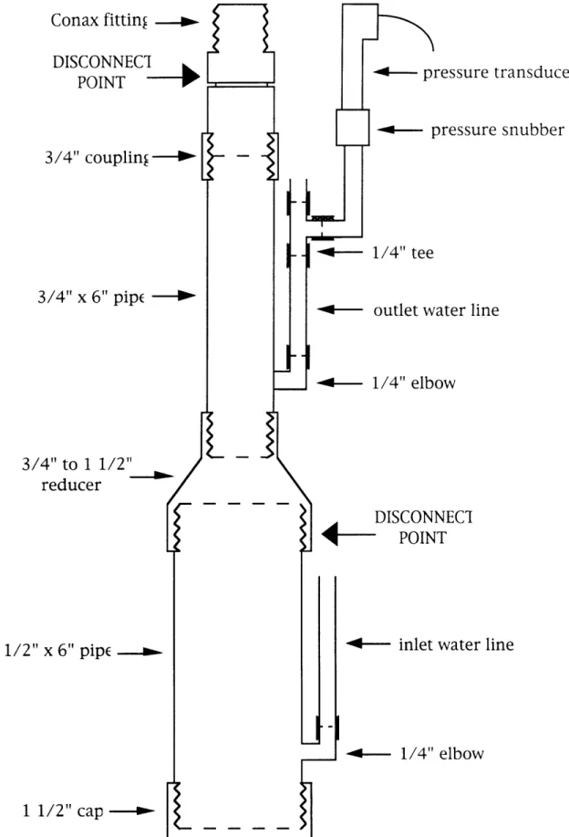
The components for the inner can were 304 stainless steel (SS). This consisted of a 3/4" coupling, a 1 1/2" cap, a 3/4" x 6" pipe, a 1 1/2" x 6" pipe, and a 3/4" to 1 1/2" reducer. On each pipe section, a 1/4" elbow was welded 1/2" above the bottom threads to form connections for water lines as shown in Figure 2.1. The inlet line entered the large pipe, and the outlet line left from the smaller pipe. Before assembling, these parts were heat treated at 800°C in air for about four hours to reduce corrosion of the vessel.
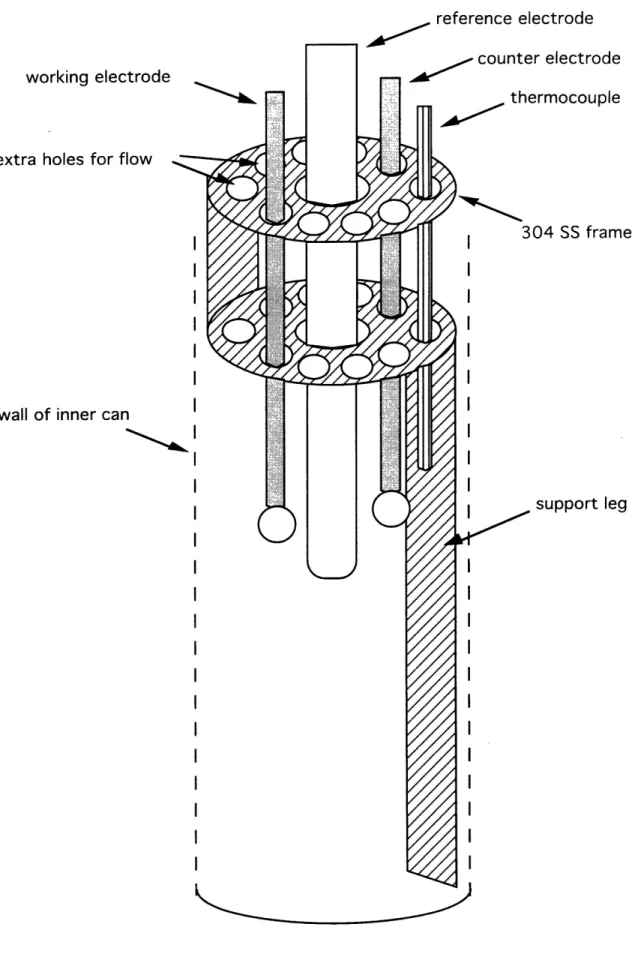
Inside the can, a 304 SS circular perforated frame was used to ensure correct placement of all electrodes and the thermocouple as illustrated in Figure 2.2. Extra holes were drilled to allow for flow through the frame.
In Figure 2.1, a 1/4" 304 SS tee on the outlet water line sent flow to the pressure snubber and transducer. At the end of the outlet water line, a 1/4" 316 SS valve controlled the pressure inside the vessel. At the top of the inner can, there was a Conax 3/4" 304 SS pressure fitting that allowed access for six 1/8" probes. The fitting seal was Viton for use from -10' to 5000F, up to 10,000
psi, and up to 2 x 10⁸ Rads. The seal was secured with an applied torque of 120-130 ft-lbs.24 Since the electrodes and thermocouple only used four of the
six available probe openings, extra mineral-insulated cable was placed in the remaining holes. When assembling the inner can, Loctite PST nuclear grade pipe sealant was used at all connection points. This was a low halogen-low sulfur sealant with certificate of test containing 200 ppm maximum chlorine and 1500 ppm maximum sulfur. It was for use from -55° to 149C and up to 2
x 108 Rads.2 5 After initial sealing of all connections, the can was designed to only be taken apart at the two points indicated in Figure 2.1 to remove the electrodes inside. The reducer-to-large pipe point was disconnected and the Conax fitting was loosened to free the thermocouple and electrode wires. An aluminum plate 1 3/4" by 3 5/8" with a central hole of 1" diameter was placed beneath the top of the Conax fitting and allowed the inner can to hang at the correct level within the outer can.
2 4
"Conax Buffalo Sealing Gland Assembly Instructions," Conax Buffalo Corporation, New York (1991).
2 5
Conax fitting -Ul3L.l Il 1 POINT
3/4" couplin
-3/4" x 6" pipe
-3/4" to 1 1/2"
reducer
1 1/2" x 6" pipe _ transducer :e snubber ine line1 1/2" cap
>Figure 2.1. Inner Can Components 1%TC'-r'KT TE/"T
reference electrode
working electrode
extra holes for flow
wall of inner can
!r electrode
ermocouple
304 .SS frnm
support leg
Figure 2.2. Inner Can Internals
2.3.2 Outer Can
The outer can was made primarily from 6061 aluminum and 304 SS. The pieces in the bottom section were all aluminum - a 3" diameter plate, a 3" x 30" pipe, a 9" x 4" square box, a 4" square plate with a 3" diameter central hole, and four 1" angles with a 3/8" diameter hole. These were welded together as shown in Figure 3.3. The top section consisted of stainless steel - a
6" square plate with four couplings welded through it for water and
instrument lines. There were also 3/8" holes that lined up with the similar holes in the angles on the bottom section. To the top of the stainless steel plate, two 1/2" 304 SS tubes for instrumentation wires and two 1/4" 304 SS
tubes for water lines were connected. The height of these tubes was
approximately 4' to allow for flexible rubber tubing to be connected outside the gamma field. To attach the upper and lower sections, a rubber gasket was placed between them, and 3/8" by 2" bolts were inserted through the four
holes and tightened with nuts and washers. To facilitate immersing this
unit under twenty feet of water in the spent fuel pool, a lead brick was placed
in the bottom of the outer can.
2.4 External Apparatus
2.4.1 Chemical Environment
Water chemistry for the fluid flowing by the electrodes was meant to
simulate the expected environment in the Yucca Mountain repository.
Water from a well near Yucca Mountain, J-13, has already been well
characterized, and its components are listed in Table 2.6.26 To prepare similar J-13 water in the laboratory, solutions of MgSO4, K2S04, Li2SO4, NaNO3, NaF,
NaCl, Na
2CO
3, Na2SO
4, SiO
2and CaCO
3were mixed in the correct
concentrations, and an ICP was used to verify that the final product was
within reasonable error margins. Potassium and sodium were tested and
found to be 5.11 ppm and 39.8 ppm, respectively; these values were both less than 10% away from the desired concentrations. Because the carbonate level
in the simulated water was less than that found in the characterized J-13
water, the pH was affected and nitric acid was added to adjust the solution
2 6
Knauss, K.G., W.J. Beiriger and D.W. Peifer, "Hydrothermal Interaction of Crushed Topopah Spring Tuff and J-13 Water at 90, 150, and 250°C Using Dickson-Type, Gold-Bag Rocking Autoclaves," Lawrence Livermore National Laboratory, California, UCRL-53630, DE86-014752 (1985).
1" angle w/ 3/8" hole 4"x 9" square box 4" square plat w/ 3" round he 3"x 30" pipe lead bri, 3" round plat( 0o 4" x 4' piping /2" x 4' pipiny velded )upling, 3/8" hole 6" square plate
Lower Section Upper Section
into the pH 7-8 range. Another difficulty with preparation of J-13 water was the low solubility of SiO2 and CaCO3 that required vigorous and lengthy
stirring of the prepared solution.
Table 2.6. Composition of J-13 Well Water
Component Concentration (ppm)
Component Concentration (ppm)
Na+ 44 HCO3- 125 K+ 5.1 NO3- 9.6 Mg2 + 1.9 S042- 18.7 Ca2 + 12.5 PO43- 0.12 SiO2 58 H202 F- 2.2 A13+ 0.012 Cl- 6.9 Fe2 + 0.006
2.4.2 Radiation Source
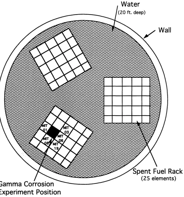
The MITR II spent fuel pool served as the radiation source for this project, with usage time donated by the MIT Nuclear Reactor Laboratory. The storage pool was a 21 foot deep steel-lined concrete tank with an 8 foot inner
diameter used to store spent fuel, control blades and other irradiated core
components. It was filled with high purity deionized water to remove the
decay heat and protect personnel working above the pool. Three storage
racks, consisting of a five by five matrix of open-ended boxes constructed of an aluminum-cadmium-aluminum sandwich, rested on the bottom of the pool. The boxes were 3.75" square on the inside, and experiment tubes could be placed in any empty storage box.2 7 The position for this project is shown in
Figure 2.4.
The radiation level for a sample depended on the burnup and decay of the surrounding spent fuel elements; for the SFP position used, the adjacent elements and their operating history are summarized in Table 2.7. Elements MIT 08 and 19 have very low burnup because they experienced clad failure early in their life, so they also have longer decay times.2 8 The dose level was
determined using radiochromic film, an aminotriphenyl methane dye
2 7MITRII Research Reactor Systems Manual, (1992).
2 8
derivative that undergoes radiation-induced coloration by photo ionization.
The film was dose rate independent to 1015 Rads/sec and had only a small temperature sensitivity. It had a linear response to ionizing radiation over a
wide range and was independent of energy down to a few keV. One
centimeter squares of film were exposed to the source, and then a photometer was used to read the change in transmission of the film. Calibration services were provided courtesy of the University of Lowell Radiation Laboratory. The radial distribution of the dose rate in our sample position peaked slightly above the center at 30,000 Rads/hr as shown in Figure 2.5.
Wntar
tack
s)
Experiment Position
Table 2.7. Spent Fuel Elements Data as of 1-1-94
Element # Burnup (MWD) Decay Time (yr)
MIT 01 3654.54 3.98 MIT 03 3733.01 2.73 MIT 06 3947.48 2.73 MIT 08 943.92 10.17 MIT 19 570.01 7.21 50- 40- 30- 20- 10-0 I .I 100 200 300
Dose Rate (Gy/hr)
Figure 2.5. Radial Dose Distribution in SFP
2.4.3 Temperature and Pressure Monitoring
The water temperature inside the sample assembly was maintained by a heater wrapped around the inner can and a thermocouple inside the can, with both connected to a temperature controller located out of pool. The flexible electric heating tape had fine-strand resistance wires insulated with braided fiberglass, knitted into flat tapes with FibroxTM fiberglass yarns and covered with heavy fiberglass fabric covering. The heater tape was a 240 VAC
am 4--1 El Approximate Location of Experiment fir~ I[ v
model of 1" width and 72" length with ties at each end to secure it and 24"
insulated lead wires emerging from opposite ends for connection to the
power source.2 9 The thermocouple was a type K ChromegaTM-AlomegaTI quick-disconnect probe with a grounded stainless steel 304 sheath 18" in length and 1/8" in diameter. It was recommended for use from -200 to 1260°C
in flowing corrosive liquids when a faster response is needed.
The
temperature controller was a 1/16 DIN auto-tune controller with PID control and 0.1°C resolution for thermocouple input.3 0
For pressure monitoring (a necessary safety precaution, although all testing was performed near atmospheric pressure), a snubber and transducer on the outlet water line were connected to a digital panel meter. The snubber contained porous metallic elements and was rated for water and light oils (30 to 225 S.S.U.) up to 15,000 psi. Its housing was SS 303 and the porous discs were SS 316.31 The transducer had a chemical vapor deposited polysilicon strain gage and was reverse polarity protected. Its operating temperature was from -40° to 125°C.32 The meter was a 3 1/2 digit panel meter consisting of a
main assembly and a plug-in strain gauge/excitation supply board. An
electrically floating supply powered transmitters, active transducers and
bridges.
It offered a high-impedance precision preamplifier with
programmable gains of 1, 3, 10, 30 and 100 to provide resolutions of 1000, 300, 100, 30 and 10 mV/count respectively. Typical offset drift was only 0.3 mV/°C, and the excitation maximum output was 20 mA at 24 V dc.3 3
2.5 Data Acquisition
2.5.1 Microscopy
After the electrodes completed the sample preparation phase, they were photographed with an optical microscope of 20X magnification using
Polaroid® pictures. The film was black and white PolaPan® ISO 400/27° 4x5
instant sheet film of medium contrast. It had panchromatic spectral
2 9
"Instruments for Research, Industry, and Education," Cole-Palmer© Instrument Company, Illinois (1994).
3 0
"CN76000 Microprocessor Based Temperature/Process Controller," OMEGA Engineering, Connecticut (1991).
31
"Pressure Snubbers PS Series," OMEGA Engineering, Connecticut (1990).
32"PX212, PX213, PX215 Pressure Transducer," OMEGA Engineering, Connecticut (1992).
3 3"DP302-E AND DP302-S Digital Panel Meter with Excitation," OMEGA Engineering,