HAL Id: cea-02338612
https://hal-cea.archives-ouvertes.fr/cea-02338612
Submitted on 21 Feb 2020
HAL is a multi-disciplinary open access
archive for the deposit and dissemination of
sci-entific research documents, whether they are
pub-lished or not. The documents may come from
teaching and research institutions in France or
abroad, or from public or private research centers.
L’archive ouverte pluridisciplinaire HAL, est
destinée au dépôt et à la diffusion de documents
scientifiques de niveau recherche, publiés ou non,
émanant des établissements d’enseignement et de
recherche français ou étrangers, des laboratoires
publics ou privés.
cutting
E. Porcheron, S. Peillon, T. Gelain, C. Chagnot, C. Journeau, E. Excoffier, V.
Testud, D. Roulet
To cite this version:
E. Porcheron, S. Peillon, T. Gelain, C. Chagnot, C. Journeau, et al.. Fukushima Dai-ichi fuel debris
retrieval analysis of aerosol emission and dispersion during simulants laser cutting. DEM 2018
-INternational Symposium on Dismantling Challenges: Industrial Reality, Prospects and Feedback
Experience, Oct 2018, Avignon, France. �cea-02338612�
Fukushima Dai-ichi fuel debris retrieval: analysis of aerosol
emis-sion and disperemis-sion during simulants laser cutting
Emmanuel Porcheron1*, Samuel Peillon1, Thomas Gelain1, Christophe Chagnot2, Christophe Journeau3, Emmanuel Excoffier4, Véronique Testud4, Damien Roulet5
1
Institut de Radioprotection et de Sûreté Nucléaire (IRSN), PSN-RES, SCA, Gif-Sur-Yvette, 91192, France
2
DEN/SEMT, CEA, Université Paris-Saclay, F-91191 Gif sur Yvette, France
3
CEA, DEN, Cadarache, SMTA/LPMA, St Paul lez Durance, 13108, France
4
CEA, DEN, Marcoule, DMRC/SA2I/LMAC, 30207, Bagnols sur Cèze, France
5
ONET Technologies, Engineering Business Unit, 26700, Pierrelatte, France
*
Emmanuel.porcheron@irsn.fr Abstract
Assessing the production and dispersion of aerosols carrying contamination during corium laser cutting opera-tions is IRSN’s contribution to a research project undertaken jointly with ONET Technologies and CEA on behalf of the Japanese Ministry of Economics, trade and Industry and managed by the Mitsubishi Research Institute. The objective is to obtain quantified data for evaluating the risk of disseminating contamination when implement-ing this technique, over the next few years, in the process of decommissionimplement-ing the damaged reactors at the Fu-kushima Dai-ichi plant.
KEYWORDS: Aerosol, airborne, resuspension, laser cutting, dismantling, Fukushi-ma
Introduction
One of the important challenges for the decommissioning of the damaged reactors of the Fukushima Daiichi Nuclear Power Plant is the retrieval of the fuel debris or corium. Given that the scenario of the severe accident that occurred in each reactor was different, the status of each power plant unit is con-sequently different. The fuel debris or corium are located inside and outside the reactor pressure ves-sel (RPV) and the molten core concrete interaction is more or less pronounced. It follows that different corium retrieval configurations have to be studied before to propose the best strategies for the disman-tling. It is especially primordial to investigate the cutting conditions for air configuration and for under-water configuration at different under-water levels. Concerning the cutting techniques, the laser technique is well adapted to the cutting of expected material such as corium which has an irregular shape. In addi-tion, the laser cutting technique induces the lowest material mass removed and the lowest mass of re-suspended aerosol during the cutting, comparatively to others cutting techniques (grinder, plasma torch, arc air, arc saw, reciprocating saw) [1]. In addition to the study of the technological aspects re-garding the capability of the cutting tool to be deployed in hostile conditions in a radiating environment, the risk of the corium retrieval operations has to be evaluated to limit the radionuclides dissemination outside the containment vessel. The characterization of the aerosol source term emitted during the laser cutting of the fuel debris is one of the key issues to evaluate the aerosol dispersion that can lead to the release of radionuclides into the environment. The determination of the size and the morphology of particles emitted during the cutting allows to predict their transport and deposition by the mean of numerical simulations. In addition, those input data are necessary to develop and optimize technolo-gies to ensure the containment, the collection and the filtration of particulate pollutants to avoid human contamination. Only a specific fraction of particulate matter (PM) is able to penetrate in the human body by the respiratory tracts. Sampling the total air concentration of particulate matter provides a crude estimate of exposure that may not correlate with observed health effects if the risk is associated only with those particles that may enter the thorax or penetrate beyond the ciliated airways. The con-cept of size-selective particle sampling has been employed as a mean for effectively sampling the particle sizes associated with specific pathologic outcomes. The human respiratory tract can be divid-ed into three main regions basdivid-ed on size, structure and function, namely, the head, the tracheobron-chial region (also known as the conducting airways), and the gas-exchange region (also known as the parenchymal, alveolar, or pulmonary regions). Relative to total airborne particles, the particle size having 50% penetration for the thoracic and respirable fractions are 10 μm and 4 μm aerodynamic
diameters respectively according to the International Standard ISO-7708 [13]. Particulate matter with a nominal mean aerodynamic diameter 10 µm (PM10) has been agreed by most regulatory agencies for being the upper critical size limit for the penetration in the respiratory tract; larger particles are general-ly filtered in the nose and throat. Similargeneral-ly, so called fine PM, often referred to as PM2.5, tend to pene-trate into the gas exchange regions of the lung (alveolus), and very small particles (< 100 nanometers) may pass through the lungs to affect other organs. The particle size range considered (< 10 µm) ac-counts also for the most mobile range of airborne particles which therefore requires the implementa-tion of specific barriers (filters, etc.) in the immediate vicinity of the source term.
Several R&D projects have therefore been launched and subsidized by the Japanese government to study and prepare operations of the corium retrieval. In this framework, a French consortium (ONET Technologies, CEA and IRSN) has been selected among others to implement R&D related to the laser cutting of Fukushima 1F fuel debris and related to dust collection technology [2].
This article deals with the characterization of the aerosol source term emitted during the laser cutting of non-radioactive simulants of fuel debris designed and manufactured by the CEA [3, 4]. Those simu-lants of fuel debris are representative from ex-vessel and in-vessel configurations. Experiments are performed in the DELIA facility operated by the CEA [2].
Description of experimental means
Laser cutting platform
The DELIA facility (French acronym for: in air and underwater laser cutting cell [2]) allows proceeding to the laser cutting of different kinds of materials. Specific laser heads have been developed for emerging and non-emerging cutting, respectively for the case where the kerf is totally crossing the piece or not.
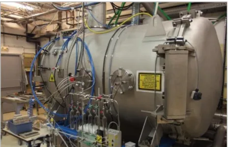
The facility, which occupies three floors, includes a laser source, a cutting cell and a test section dedi-cated to the analysis of aerosols emitted during the cutting (Figure 1). At the top floor, the aerosol sam-pling line is installed allowing the measurement of the aerosol particle concentration and the charac-terization of their size distribution and morphology.
The cutting cell presented in Figure 2 is a stainless steel tank with a diameter of 1.38 meter and a length of 2 meters with a usable volume of 3.7 m3 (5 m3 including chimneys). It is equipped with two chimneys of 5 m in height; one of them with an inner diameter of 250 mm is used for the exhaust of the aerosol particles and the gas. The ventilation in the facility is produced by compressed air injected at the laser head located in the cutting cell with a volume flow rate up to 180 m3.h-1. Laser cutting tests can be performed in air condition and underwater condition at different water levels (up to 5.6 m high).
The laser source is a continuous wave Nd:YAG laser with a rated power of 8 kW at a wavelength of 1.03 µm from the TRUMPF Company. A flushing air jet surrounding the laser beam evacuates the mol-ten metal sprayed by the laser during the cutting operation. The cutting speed is defined as a function of the thickness of the piece and its physico-chemical properties (in particular fusion temperature).
The cutting performances of the laser have been previously studied and, for each material thickness and laser power intensity, the maximum speed limit has been measured [5].
Figure 1. Sketch of the DELIA facility and aerosol loop
Figure 2. View of the cutting cell of the DELIA facility
Corium simulants
The ex-vessel fuel debris simulant composition has been determined by CEA [4] from calculations by Japanese and International experts on an ex-vessel scenario with Molten Core concrete Interaction in the sump of Fukushima Daiichi Unit 1 pedestal sump (configuration maximizing the fraction of con-crete decomposition products) including the fission products inventory 10 years after the accident [6][7] (Figure 3). The in-vessel fuel debris simulant (Figure 4) composition has been determined [4] from the average of the Fukushima Daiichi unit 2 lower head debris composition calculated within the OECD/BSAF project [8] in which the fission products inventory 10 years after the accident has been considered. As described in [4], uranium has been simulated by hafnium and plutonium by cerium, whereas fission products have been considered with the natural isotopic composition of the respective chemical elements. Neodymium, molybdenum, cesium, cerium, barium, lanthanum, palladium, prase-odymium, samarium, strontium, yttrium and tellurium have been introduced in the load. The repre-sented isotopes correspond to 95% of the radioactivity inventory from 1F1 at the considered date (10 years after the accident).
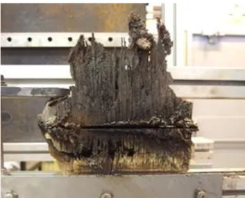
Figure 3. View of laser-cut fuel debris simulant for ex-vessel configuration
Figure 4. View of laser-cut fuel debris simulant for in-vessel configuration
Test section for aerosol characterization
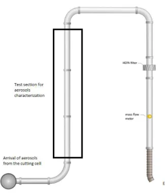
The aerosol source term characterization is performed using a specific test section implemented on the top floor of the DELIA facility (Figure 1). This characterization is carried out through the meas-urements of the mass concentration, the particle size distribution and the composition of the aero-sols that are sampled in the aerosol test section connected to exhaust line of the DELIA laser cut-ting cell (Figure 5) [12]. Different instruments are implemented on the aerosol test section to pro-vide together real time and integrated measurements of aerosol characteristics (Figure 6). The po-sitions of these instruments in the test section are depicted in the Figure 6. All mechanisms in-volved in the transport and the deposit of particles in the cylindrical sampling line have been inte-grated in a numerical tool (AEROCALC). This software can calculate, for different kinds of geome-tries and singularities, the aerosol deposition fraction in the sampling line (or aerosol penetrating fraction) function of flow conditions and aerodynamic diameters of particles. For the smaller aero-dynamic diameters, 0.03 µm and 1 µm, the penetrating fractions are equal to 99 %, meaning that the losses in the sampling line up to the different instruments are negligible.
Figure 5. Sketch of the loop dedicated to aerosols sampling
Figure 6. Test section for aerosols measurements
The physical quantities regarding airborne aerosols measured during laser cutting tests are the fol-lowing:
the mass concentration of the aerosol by filter sampling,
the time evolution of the aerosol mass concentration using a Pegasor PPS-M aerosol sensor, the particles size distribution according to the aerodynamic diameter using a Low Pressure
Impactor (Dekati® DLPI),
the volume flow rate in the exhaust line,
the pressure drop of the HEPA filter positioned downstream in the exhaust line,
the qualitative chemical composition of the collected particles on sampling filter using a coupled analysis of Scanning Electron Microscopy (SEM) or Transmission Electron Microscopy (TEM) and Energy-Dispersive X-ray Spectroscopy (EDS) analysis,
Results and discussion on aerosol source term characterization
Aerosol size
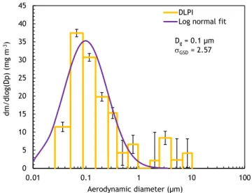
The particle mass size distributions obtained with the low pressure impactor (DLPI) are presented in Figure 9, Figure 10 and Figure 11, respectively for ex-vessel simulant in air and underwater conditions and for in-vessel simulant in air condition with their uncertainty at 95% confidence interval. Log-normal distributions have been fitted on the data.
Figure 9. Particle mass size distribution obtained with the DLPI for the ex-vessel simulant in air condi-tion
Figure 10. Particle mass size distribution obtained with the DLPI for the ex-vessel simulant underwater condition at 0.35 m water depth
0 5 10 15 20 25 30 35 40 45 0.01 0.1 1 10 100 dm /d lo g(D p) (mg m -3) Aerodynamic diameter (µm) DLPI Log normal fit Dg= 0.1 µm
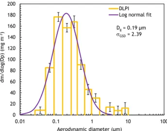
Figure 11. Particle mass size distribution obtained with the DLPI for the in-vessel simulant in air condi-tion
As one can see, the agreement with the log-normal law is not obvious for the particle mass size distri-butions measured for the ex-vessel and for the in-vessel simulants. Indeed, the spread of the distribu-tions is significant and the fitted geometric standard deviation is equal to 2.57 for the ex-vessel air cutting (1.51 for underwater cutting) and 2.39 for the in-vessel air cutting. The fitted geometric mean diameters are small and equal to 100 nm for the ex-vessel cutting in air, 300 nm for underwater condi-tion and 190 nm for the in-vessel cutting. For the air cuttings, we can also notice the presence of a second mode in the particle mass size distributions corresponding to large particle aerodynamic diam-eters between 2 µm and 10 µm. This second mode is attenuated for underwater cutting due to high pool scrubbing efficiency for aerosols larger than 1 micron.
The particle mass median diameters measured for underwater condition is larger than for air condition (from 300 nm to 100 nm). This result can be attributed to the fact that for underwater conditions, the aerosol number concentration near the cutting location in the gas bulk produced by the laser head is higher than for air condition, which promotes the agglomeration phenomena. Those size differences are significant especially since we must recall that efficiency of filters, used for gas filtration to ensure the containment of aerosol, is mainly depending on the aerosol size. For a HEPA (High Efficiency Particulate Air) filter, the minimum efficiency is reached for aerosols around 0.15 µm [9].
Mass concentration of the resuspended aerosols
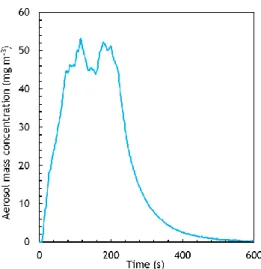
The time evolution of the particle mass concentrations measured with the Pegasor sensor during the cuttings of in-vessel and ex-vessel simulants are presented in Figure 12 and Figure 14 for air condi-tion, and for underwater condition for ex-vessel simulant in Figure 13. The measurements cover the entire cutting period and were kept running until the signal returns to the background noise observed in the facility before the start of the laser.
0 20 40 60 80 100 120 140 160 180 200 0.01 0.1 1 10 100 dm /d lo g(D p) (mg m -3) Aerodynamic diameter (µm) DLPI Log normal fit Dg= 0.19 µm GSD= 2.39
Figure 12. Time evolution of the aerosol mass concentration for ex-vessel simulant during laser cutting in air condition
Figure 13. Time evolution of the aerosol mass concentration for ex-vessel simulant during laser cutting for underwater condition at 5.6 m water depth
Figure 14. Time evolution of the aerosol mass concentration for in-vessel simulant during laser cutting in air condition 0 2 4 6 8 10 12 0 50 100 Ma ss c oncent rat io n ( m g/ m 3) Time (s)
The difference observed for aerosols produced during the air cutting of both simulants in terms of size can be attributed to the difference of composition and physico-chemical properties such as the fusion temperature which is higher for the in-vessel simulant [4]. Due to its higher fusion temperature, the laser cutting of the in-vessel simulant induces an increase of the vaporization processes leading to the production of higher concentration of aerosols (about four times more for vessel simulant). The in-crease of the emission of aerosol concentration has a direct influence on aerosol agglomeration pro-cesses that occur in the cutting cell, leading to an increase of the particle size (0.1 µm for ex-vessel simulants compared to 0.19 µm for in-vessel simulant) [10]. This difference may seem low but con-tainment strategies of mitigation means against aerosols dispersion will be impacted by aerosol ag-glomeration phenomena.
Aerosol morphology
The morphology of aerosols emitted during the laser cutting was characterized for air condition, for zirconia block, ex-vessel and in-vessel simulants. The particle morphology is a physical quantity which gives information about the phenomena leading to the aerosol formation. In addition, aerosol morphol-ogy has an impact on the clogging dynamics of HEPA filters. Indeed, fractal morpholmorphol-ogy of combus-tion soot is a parameter of increase of filters clogging [11]. Aerosols were sampled during the cutting in order to visualize their shape using SEM (Scanning Electron Microscopy) and TEM (Transmission Electron Microscopy). Their shape is characteristic of the processes of aerosol formation by material fusion and vaporization, for certain conditions, and followed by the agglomeration of primary particles whose sizes are about few nanometers.
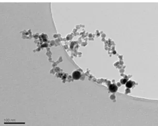
Results are presented in Figure 15, Figure 16 and Figure 17. One can notice the type of morphology characteristic of fractal one like combustion soot (fractal dimension of particles is around 1.8), for aer-osols produced during laser cutting of ex-vessel and in-vessel simulants (Figure 16 and Figure 17).
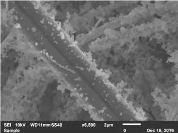
Figure 15. Visualization by Scanning Electron Microscope of aerosol produced during the cutting of zirconia block, collected on filter fibers
Figure 16. Visualization by Transmission Electron Microscope of aerosol produced during the cutting of ex-vessel simulant
Figure 17. Visualization by Transmission Electron Microscope of aerosol produced during the cutting of in-vessel simulant
Aerosols from the in-vessel simulant have a more agglomerated structure than the ex-vessel one, that is coherent with the higher measured concentrations (Figure 14) leading to the emphasis of the ag-glomeration phenomena [10, 14]. We can also make the assumption that the higher fusion tempera-ture of the in-vessel simulant, and its different composition, have an influence on the aerosol morphol-ogy.
Aerosol composition
The quartz filters used for the global mass concentration measurement were analyzed by the CEA to determine the aerosol chemical composition. After the retrieval of the particle deposits and dissolution of the material in solution, the remaining solutions were analyzed by means of ICP-MS technique. Results of the chemical analysis are presented in Figure 18 for ex-vessel and in-vessel simulants in air condition. Results are expressed in terms of relative quantities of each element considered in the samples analyzed.
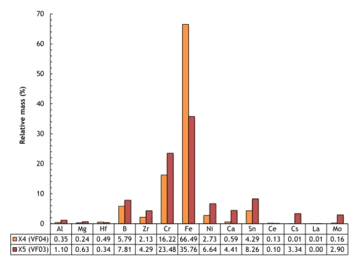
Figure 18. Chemical composition of the particles sampled with the quartz filters during ex-vessel (VF03) and in-vessel (VF04) simulants in air condition.
For the ex-vessel simulant in air condition, the major constituents of the resuspended aerosols are iron (36 wt%), chromium (23 wt%), tin (8 wt%), Boron (8 wt%), Nickel (7 wt%), zirconium and calcium (4 wt%) and cesium and molybdenum (3 wt%).
For the in-vessel simulant in air condition, the major constituents of the resuspended aerosols are iron (66 wt%), chromium (16 wt%), Boron (6 wt%), tin (4 wt%), Nickel (3 wt%) and zirconium (2 wt%).
Aerosol source term dispersion
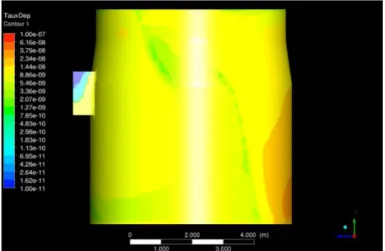
The knowledge of the aerosol source term emitted during the laser cutting operation is essential to predict the transport and the deposition of airborne particles. Numerical simulations using CFD (Com-putational Fluid Dynamics) approach have been achieved to evaluate the deposition of the aerosols during the laser cutting in a geometry representative of the pedestal of the BWR reactor. The laser cutting system is located at the center part of the pedestal ground. The complete description of the physical models used in those numerical simulations is presented in [10].
Figure 19. Aerosol deposition fraction on the ground of the BWR pedestal for aerosol diameter equal to 0.1 µm Al Mg Hf B Zr Cr Fe Ni Ca Sn Ce Cs La Mo X4 (VF04) 0.35 0.24 0.49 5.79 2.13 16.22 66.49 2.73 0.59 4.29 0.13 0.01 0.01 0.16 X5 (VF03) 1.10 0.63 0.34 7.81 4.29 23.48 35.76 6.64 4.41 8.26 0.10 3.34 0.00 2.90 0 10 20 30 40 50 60 70 Re lati ve mas s (%)
Ground
Figure 20. Aerosol deposition fraction on the wall of the BWR pedestal for aerosol diameter equal to 0.1 µm
Numerical results on Figure 19 and Figure 20 show that only 1.5 % of the aerosol fraction correspond-ing to aerosol size of 0.1 µm is deposited on the different walls of the BWR pedestal, that means 99% could be transported and disseminated in the containment vessel in the absence of countermeasures such as aerosol collection devices.
CONCLUSION
This paper gives a presentation of a part of the research works undertaken by the consortium ONET/CEA and IRSN in order to demonstrate the feasibility of the use of the laser cutting technique for the removal of fuel debris in the damaged reactors of Fukushima Dai-ichi. This paper focuses on the risk of the dismantling operations induced by the dispersion of radioactive aerosols emitted during the laser cutting of fuel debris. Both experimental and numerical approaches allowed to characterize the aerosol source term produced during the cutting operations of fuel debris simulants and the predic-tion of its transport and deposipredic-tion in representative geometry of BWR pedestal. Characterizapredic-tion was made based on airborne mass concentration, size and morphology. Further work is underway by tak-ing into account the aerosol chemical composition in relation with the radioactivity it would carry for actual fuel debris.
Results highlighted the difference of the aerosol source term characteristics versus ex-vessel and in-vessel simulants which have to be considered in the simulations of aerosol dispersion.
Acknowledgments
This work has been carried out thanks to the subsidized project of Decommissioning and Contaminat-ed Water Management (Development of Fundamental Technologies for Retrieval of Fuel Debris and Internal Structures) funded by the Japanese Ministry of Economy, Trade and Industry (METI) and managed by the Mitsubishi Research Institute (MRI). The authors thank Mrs Christine Georges in charge of the general management of the project for the CEA.
References
[1] Pilot, G., Fauvel, S., Gosse, X., de Dinechin, G., Vernhet, D. (2008). Measurement of secondary emissions during laser cutting of steel equipments. Nucl. Eng. Des. 238: 2124–2134.
[2] Georges, C., Roulet, D., Chagnot C., Journeau, C., Canneau G., Blanchard S., Porcheron E., Ben-efits from developments in the field of Decommissioning for Fukushima Daiichi fuel debris retriev-al: Remote-Controlled Laser Cutting Process, Proc. WM2017 Conference, 2017 March 6- 9, Phoenix, AZ, United States.
[3] Journeau C., Monneris J., Tormos B., Brissonneau L., Excoiffier E., Testud V., Chagnot C., Roulet D., Fabricating Fukushima Daiichi in-vessel and ex-vessel fuel debris simulants for the develop-ment and qualification of laser cutting technique, Proc. ERMSAR-2017 (Eur. Rev. Mtg Sev. Acci-dent Res.), 2017 May 16-18. Warsaw, Poland.
[4] Journeau, C,. Roulet, D., Porcheron, E., Piluso, P., Chagnot, C. (2018). Fukushima Daiichi fuel debris simulant materials for the development of cutting and collection technologies, Journal of
Nuclear Science and Technology.
[5] Chagnot, C., de Dinechin, G. and Canneau, G. (2010). Cutting performances with new industrial continuous wave ND: YAG high power lasers: For dismantling of former nuclear workshops, the performances of recently introduced high power continuous wave ND:YAG lasers are assessed.
Nucl. Eng. Des. 240: 2604–2613.
[6] Robb, K., Francis, M.W., Farmer, M.T, Ex-Vessel Core Melt Modeling Comparison between MELTSPREAD-CORQUENCH and MELCOR 2.1, Oak Ridge National Lab report ORNL/TM-2014/1, 2014.
[7] Nishihara, K., Iwamoto, H., Suyama, K., Estimation of Fuel Compositions in Fukushima-Daiichi Nuclear Power Plant, JAEA Report JAEA-Data/Code 2012-018, 2012.
[8] Pellegrini, M., Dolganov, K., Herranz Puebla, L.E., Bonneville, H., Luxat, D., Sonnenkalb, M., Ishi-kawa, J., Song, J.H., Gauntt, R.O., Fernandez Moguel, L., Payot, F., Nishi, Y., Benchmark Study of the Accident at the Fukushima Daiichi NPS Best Estimate Case Comparison, NURETH 16, Chicago, IL, 2015.
[9] Gervais, P-C., Bourrous, S., Dany, F., Bouilloux, L., Ricciardi; L., Computers and Fluids, Volume 116, August 05, 2015, Pages 118-128.
[10] Gelain, T., Porcheron, E., Chagnot, C., Roulet, D., CFD simulations of aerosol dispersion and agglomeration during the laser cutting of Fukushima fuel debris simulants, ICONE26, 2018. [11] Ouf, F-X., Mocho, V., Pontreau, S., Wang, Z., Ferry, D., Yon, J., Clogging of industrial High
Effi-ciency Particulate Air (HEPA) filters in case of fire: From analytical to large-scale experiments,
Aerosol Science and Technology, Volume 48, Issue 9, 2014, Pages 939-947.
[12] Peillon, S., Fauvel, S., Chagnot, C. and Gensdarmes, F. (2017) Aerosol Characterization and Particle Scrubbing Efficiency of Underwater Operations during Laser Cutting of Steel Compo-nents for Dismantling of Nuclear Facilities, Aerosol and Air Quality Research, 17: 1363–1373. [13] ISO. 1995. Air Quality – Particles size fractions definitions for health-related sampling. Geneva:
International Standards Organisation, ISO Standard 7708.
[14] Porcheron, E., Peillon, S., Gelain, T., Chagnot, C., Journeau, C., Roulet, D., Analysis of aerosol emission and dispersion during the laser cutting of Fukushima fuel debris simulants, 2018.