Publisher’s version / Version de l'éditeur:
Vous avez des questions? Nous pouvons vous aider. Pour communiquer directement avec un auteur, consultez la première page de la revue dans laquelle son article a été publié afin de trouver ses coordonnées. Si vous n’arrivez pas à les repérer, communiquez avec nous à [email protected].
Questions? Contact the NRC Publications Archive team at
[email protected]. If you wish to email the authors directly, please see the first page of the publication for their contact information.
https://publications-cnrc.canada.ca/fra/droits
L’accès à ce site Web et l’utilisation de son contenu sont assujettis aux conditions présentées dans le site LISEZ CES CONDITIONS ATTENTIVEMENT AVANT D’UTILISER CE SITE WEB.
Internal Report (National Research Council of Canada. Division of Building
Research), 1983-09
READ THESE TERMS AND CONDITIONS CAREFULLY BEFORE USING THIS WEBSITE.
https://nrc-publications.canada.ca/eng/copyright
NRC Publications Archive Record / Notice des Archives des publications du CNRC :
https://nrc-publications.canada.ca/eng/view/object/?id=9cb4dbcb-d9f1-4bbc-af7d-f5e17c4b2f8b https://publications-cnrc.canada.ca/fra/voir/objet/?id=9cb4dbcb-d9f1-4bbc-af7d-f5e17c4b2f8b
NRC Publications Archive
Archives des publications du CNRC
For the publisher’s version, please access the DOI link below./ Pour consulter la version de l’éditeur, utilisez le lien DOI ci-dessous.
https://doi.org/10.4224/40001327
Access and use of this website and the material on it are subject to the Terms and Conditions set forth at
Fire tests on reinforced concrete columns: specimen no. 6
Ser
TH1
R427
1
n.
483
k
National Research Conseil national Council Canada de recherche5 Canada
FIRE TESTS ON REINFORCED CONCRETE COLUMNS, SPECIMEN No. 6 by T.T. L i e and T.D. L i n
Private copy for:
7
DBR Internal Report
483
NATIONAL RESEARCH COUNCIL OF CANADA DIVISION OF BUILDING RESEARCH
OBR INTERNAL REPORT NO.
483
FIRE TESTS ON REINFORCED CONCRETE COLUMNS, SPECIMEN No. 6
by T.T. Lie and T.D. Lin
Checked by: T - 2 . H. Approved by: L
.W.
Gold Date: September 1983Prepared for: Records Purposes
ABSTRACT
Results of a f i r e t e s t on a reinforced concrete column a r e given. The t e s t i s one of a s e r i e s of twelve t e s t s c a r r i e d out i n t h e f i r s t phase of a j o i n t study on t h e f i r e performance of concrete columns by t h e National Research Council Canada and t h e Portland Cement Association. The column was made with s i l i c e o u s aggregate. I t s s e c t i o n s i z e was 203 x 203 mm (8 x 8 in.). It was t e s t e d t o study t h e heat t r a n s f e r i n the column.
FIRE TESTS ON REINFORCED CONCRETE COLUMNS SPECIMEN NO. 6
by
T
.To
L i e and T .D. Lin*T e s t s were c a r r i e d o u t on a s e r i e s of r e i n f o r c e d c o n c r e t e columns a s a p a r t of a study t o develop methods f o r t h e d e t e r m i n a t i o n of t h e f i r e r e s i s t a n c e of such columns. The s t u d y was a c o o p e r a t i v e e f f o r t between t h e N a t i o n a l Research Council Canada and t h e P o r t l a n d Cement Association. I n t h e f i r s t phase of t h e s t u d y 12 columns were t e s t e d . The c o l u r ~ n s were designed and manufactured by PCA i n Skokie, I l l i n o i s , and t e s t e d i n t h e NRCC l a b o r a t o r i e s i n Ottawa. The test specimens, method of t e s t i n g and t e s t r e s u l t s a r e d e s c r i b e d i n s u c c e s s i v e r e p o r t s .
This r e p o r t d e a l s w i t h specimen No. 6 , which was t e s t e d t o s t u d y t h e h e a r t r a n s f e r i n t h e column.
TEST
SPECIMEN
The specimen c o n s i s t e d of
a
s q u a r e t i e d r e i n f o r c e d c o n c r e t e column. D e t a i l s of t h e specimen and i t s f a b r i c a t i o n a r e g i v e n below.Dimensions
S e c t i o n s i z e : 203 x 203 mm ( 8 x 8 i n . ) Height: 3810 mm (12 f t 6 in.)
Materials
Cement: Type I , a g e n e r a l purpose cement f o r t h e c o n s t r u c t i o n of r e i n f o r c e d c o n c r e t e s t r u c t u r e s .
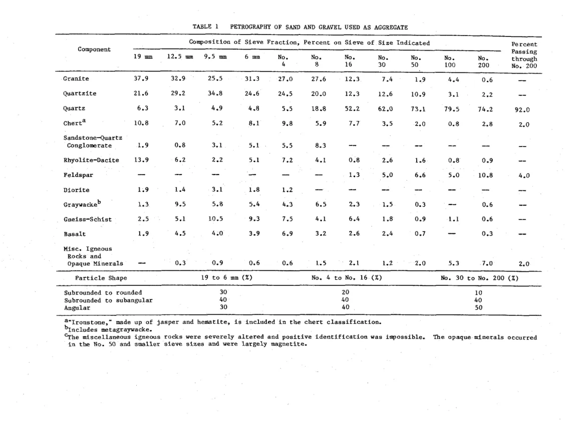
Aggregate: S i l i c e o u s sand and g r a v e l from Eau C l a i r e , Wisconsin. The maximum s i z e of t h e a g g r e g a t e was 19 mm (314 i n . ) . The g r a d a t i o n curve i s shown i n Fig. 1. P e t r o g r a p h i c i n f o r m a t i o n on t h e a g g r e g a t e , o b t a i n e d a c c o r d i n g t o ASTM ~ 2 9 5 - 7 g 1 , i s g i v e n i n T a b l e 1. P h y s i c a l p r o p e r t i e s of a g g r e g a t e : S p e c i f i c g r a v i t y of sand (2.63); s p e c i f i c g r a v i t y of g r a v e l (2.57); m o i s t u r e content of sand (4.0%); m o i s t u r e c o n t e n t of g r a v e l (1.0%); s a t u r a t e d s u r f a c e dry u n i t weight of g r a v e l (1678 kg/m3) (104.9 l b / f t 3 ) ; f i n e n e s s modulus of f i n e a g g r e g a t e (2.96); f i n e n e s s modulus of c o a r s e aggregate (1.73).
*Senior r e s e a r c h e n g i n e e r , P o r t l a n d Cement A s s o c i a t i o n , Skokie, I l l i n o i s .
S t e e l reinforcement: Deformed 20M (No. 6 ) l o n g i t u d i n a l
r e i n f o r c i n g b a r s and 10M (No. 3) t i e s , ineeting t h e requirements of ASTM Designation: ~615-602. The y i e l d s t r e s s of t h e 20M b a r s was 442 MPa
(64.1 k s i ) and t h a t of t h e 10M b a r s , 426.5 MPa (61.8 k s i ) . The u l t i m a t e s t r e n g t h of t h e 20M b a r s was 721 MPa (104.5 k s i ) and of t h e
10M b a r s , 671 MPa (97 k s i ) .
Concrete mix: The c o n c r e t e mix was designed t o produce a 34.5 MPa (5000 p s i ) s t r e n g t h n o n - a i r e n t r a i n e d c o n c r e t e . A waterfcement r a t i o of 0.6 was used. The slump was 76 m (3.00 i n . ) . Batch q u a n t i t i e s a r e a s follows: cement, 307.3 kg/m3 (5 18 1bfyd 3 ) ; c o a r s e a g g r e g a t e ,
1054.3 kg/m3 (1777 1 b f y d 3 ) ; sand, 871.5 kg/m3 (1469 1 b I y d 3 ) ; w a t e r , 153.7 kg/m3 (259 1blyd3). The measured p r o p e r t i e s of t h e c o n c r e t e were: a i r c o n t e n t , 1.60%; d e n s i t y , 2396 kg/m3 (149.55 l b / f t 3);
compressive s t r e n g t h a t 28 days ( c a s t d a t e , 26 J u l y , 1977), 34.8 MPa (5040 p s i ) .
Fabrication C a s t i n g
The column was c a s t i n a s p e c i a l l y designed form. A t t h e s t a r t of c a s t i n g , t h e f r o n t of t h e form was l e f t open f o r d e p o s i t i n g f r e s h c o n c r e t e . The concrete was mixed i n a 0.17 m 3 (6 f t 3 ) t i l t i n g drum mixer. Shovels and scoops were used t o d e p o s i t c o n c r e t e i n t h e form.
A s m a l l i n t e r n a l v i b r a t o r was a p p l i e d t o c o n s o l i d a t e t h e c o n c r e t e . A s t h e c a s t i n g p r o g r e s s e d upwards, t h e window p i e c e s were s u c c e s s i v e l y c l o s e d and t i g h t l y b o l t e d t o t h e form t o a v o i d p o s s i b l e moisture l e a k s . L i f t i n g hooks were embedded on o p p o s i t e s i d e s of t h e t e s t specimen 800 m ( 2 f t 7 112 i n . ) from t h e t o p of t h e column. A c y l i n d r i c a l humidity w e l l 3 w i t h a diameter of 4 mm (5132 i n , ) was p o s i t i o n e d a t mid-height of t h e column f o r measuring t h e r e l a t i v e humidity a t mid- depth.
R e i n f o r c i n g cage
The r e i n f o r c i n g cage was assembled by welding each end of f o u r l o n g i t u d i n a l main r e i n f o r c i n g b a r s t o a s t e e l end p l a t e . The b a r s were c u t t o 3800 mm (12 f t 5 112 i n . ) and machined a t both ends, f o r a
l e n g t h of 19 mm (314 i n . ) t o a d i a m e t e r of 19 mm (314 in.). F i g u r e 2 shows d e t a i l s of t h e f i n i s h e d bars. The dimensions of t h e end p l a t e s were 533 x 533 x 25 mm (21 x 21 x 1 i n . ) . I n each c o r n e r of t h e p l a t e , 20.6 m h o l e s (13116 i n . ) were d r i l l e d t o accommodate t h e l o n g i t u d i n a l bars. The c e n t e r s of t h e h o l e s were spaced 44.5 mm ( 1 314 in.) from t h e c e n t e r l i n e s of t h e p l a t e s . I n t h i s way a column was o b t a i n e d w i t h a s e c t i o n of 203 x 203 mm ( 8 x 8 in.) and a cover of 47.6 mm
(1 718 i n . ) t o t h e main r e i n f o r c i n g b a r s and 38.1 mm (1 112 i n . ) t o t h e s t i r r u p s . The main b a r s and s t i r r u p s were t i e d t o g e t h e r t o complete t h e s t e e l cage which, i n c l u d i n g t h e s t e e l p l a t e s , was 3810 mm
Welding
The p r o v i s i o n s of AWS Designation ~ 1 2 . 1 - 7 5 were followed when welding p l a t e s and b a r s . These members were preheated w i t h a propane t o r c h t o 288OC (550°F), t o p r e v e n t b r i t t l e f a i l u r e d u r i n g welding. The s i d e f i l l e t weld was done around b a r s on t h e i n n e r f a c e of t h e bottom p l a t e . McKay E10018-D2 and DYTRON-579 welding r o d s were used. Both t y p e s of welding r o d s have t e n s i l e s t r e n g t h of 834.9 MPa (121 000 p s i ) . Mild-steel welding rods were used t o f i l l up t h e 6 mm (114 i n . ) deep h o l e s on t h e o u t e r f a c e s of t h e p l a t e . The rough s u r f a c e s of t h e welded j o i n t s on t h e o u t e r f a c e of t h e p l a t e were ground t o
a
smoothf i n i s h .
The welding of t h e t o p s t e e l p l a t e was performed a f t e r t h e c a s t i n g of t h e columns. Before p o s i t i o n i n g t h e t o p p l a t e a 6 mm (1/4 i n . )
l a y e r of mortar was s p r e a d over t h e t o p of t h e column t o e n s u r e good c o n t a c t between s t e e l p l a t e and concrete. The mortar was made of 1 p a r t cement and 3 p a r t s s i l i c e o u s sand. Using t h e same procedure a s f o r t h e bottom p l a t e , t h e t o p p l a t e was welded o n t h e o u t e r s i d e t o t h e b a r s and smoothed.
Curing
The c o n c r e t e was cured under damp b u r l a p f o r 7 days a t 21 t o 24'C ( 7 0 t o 75°F). The form was t h e n s t r i p p e d , and t h e column k i l w d r i e d a t about 93°C (200°F) and 0 t o 5% r e l a t i v e humidity. The column, which was t o be t e s t e d a t a n e a r o v e n - d r y c o n d i t i o n , was removed f r o m t h e k i l n p e r i o d i c a l l y t o c o o l a t 23'C (73'F) s o t h a t t h e r e l a t i v e humidity
i n t h e c o n c r e t e could be measured. Moisture c o n t e n t i n t h e column d u r i n g t h e d r y i n g p e r i o d i s g i v e n below.
Days a f t e r R e l a t i v e humidity c a s t i n g c e n t e r of column ( % )
Two hundred t h i r t e e n days a f t e r c a s t i n g , t h e n e a r d r y c o n d i t i o n was reached, and t h e column was wrapped i n p l a s t i c t o p r e v e n t
a b s o r p t i o n of m o i s t u r e from t h e environment. Thermocouples
Butt-welded chromel-alumel thermocouples w i t h a t h i c k n e s s of 0.912 mm (0.0359 i n . ) were used t o make thermocouple frames f o r measuring c o n c r e t e temperatures a t d i f f e r e n t l o c a t i o n s i n v a r i o u s c r o s s s e c t i o n s of t h e columns. Each frame c o n s i s t e d of a number of thermocouples t i e d t o s t e e l r o d s t h a t were f i r m l y secured t o t h e main r e i n f o r c i n g b a r s . Temperatures w e r e measured a t t h r e e l e v e l s : a t one-
q u a r t e r h e i g h t , a t mid-height and a t t h r e e - q u a r t e r h e i g h t of t h e column. A t mid-height t h e temperatures were measured a l o n g t h e whole l e n g t h of a c e n t e r l i n e and d i a g o n a l of t h e s e c t i o n ; a t t h e o t h e r two l e v e l s t h e temperatures were measured o n l y a l o n g h a l f of t h e c e n t e r l i n e and h a l f of t h e d i a g o n a l of t h e s e c t i o n . The l o c a t i o n of t h e
thermocouples i n t h e c o n c r e t e and t h e i r numbering a r e Shown i n F i g s . 3 and 4.
I n a d d i t i o n , a number of thermocouples were mounted on t h e
r e i n f o r c i n g s t e e l b a r s and t i e s . The l o c a t i o n s of t h e thermocouples on t h e s t e e l a r e shown i n F i g . 5 and i n more d e t a i l i n Fig. 6.
A l l thermocouples were i n s t a l l e d i n such a way t h a t t h e w i r e followed a n i s o t h e r m f o r a t l e a s t 12.7 mm (112 in.) from t h e j u n c t i o n . Test Apparatus
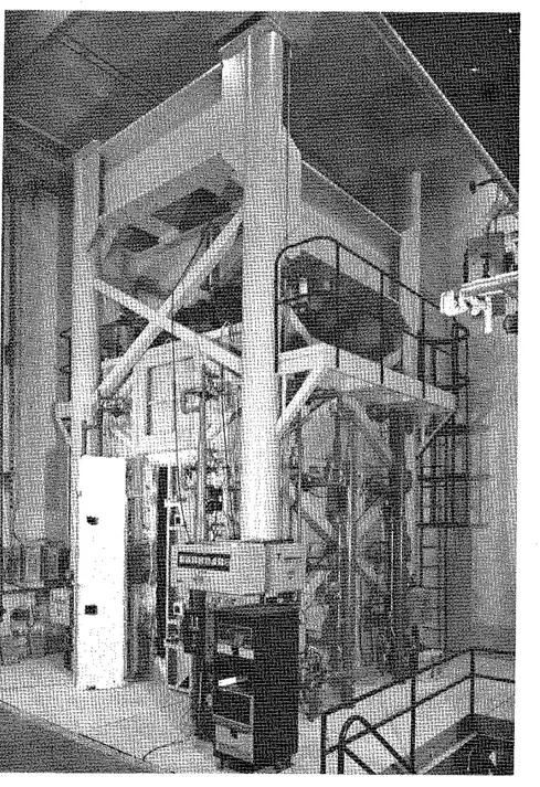
The t e s t was c a r r i e d o u t by exposing t h e column t o h e a t i n a f u r n a c e s p e c i a l l y b u i l t f o r t h e t e s t i n g of loaded columns and w a l l s . The t e s t f u r n a c e was designed t o produce t h e c o n d i t i o n s t o which a member might be exposed d u r i n g a f i r e , i.e. t e m p e r a t u r e s , s t r u c t u r a l l o a d s , and h e a t t r a n s f e r . It c o n s i s t s of a s t e e l framework s u p p o r t e d by f o u r s t e e l columns w i t h t h e f u r n a c e chamber i n s i d e t h e framework
(Fig. 7 ) . The c h a r a c t e r i s t i c s and i n s t r u m e n t a t i o n of t h e f u r n a c e a r e d e s c r i b e d i n d e t a i l i n r e f e r e n c e 5. Only a b r i e f d e s c r i p t i o n of t h e f u r n a c e and t h e main components w i l l be g i v e n here.
Loading Device
Three h y d r a u l i c j a c k s produce f o r c e s a l o n g t h e t h r e e p r i n c i p a l axes. The j a c k a c t i n g a l o n g t h e a x i s of t h e t e s t column i s l o c a t e d a t t h e bottom of t h e f u r n a c e chamber. The p l a t e on t o p of t h i s j a c k can be used a s a p l a t f o r m t o which t h e column can be a t t a c h e d .
Furnace Chamber
The f u r n a c e chamber has a f l o o r 2642 mm ( 8 f t 8 i n . ) on each s i d e and i s 3048 mm (10 f t ) high. It i s made of i n s u l a t i n g m a t e r i a l s t h a t w i l l produce a h i g h h e a t t r a n s f e r t o t h e specimen. There a r e 32 propane g a s b u r n e r s i n t h e f u r n a c e chamber, a r r a n g e d i n e i g h t columns c o n t a i n i n g f o u r b u r n e r s each. The t o t a l c a p a c i t y of t h e b u r n e r s is
4700 kW (16 m i l l i o n Btu/h). Each b u r n e r can be a d j u s t e d i n d i v i d u a l l y , which a l l o w s a h i g h temperature u n i f o r m i t y i n t h e f u r n a c e chamber. The p r e s s u r e i n t h e f u r n a c e chamber i s a l s o a d j u s t a b l e . It was s e t
somewhat lower t h a n atmospheric p r e s s u r e . Instrumentation
The f u r n a c e t e m p e r a t u r e s a r e measured w i t h t h e a i d of e i g h t chromel-alumel thermocouples. The j u n c t i o n of each thermocouple was l o c a t e d 305 mm ( 1 f t ) from t h e t e s t specimen, a t v a r i o u s h e i g h t s . Two thermocouples a r e p l a c e d o p p o s i t e e a c h o t h e r e v e r y 610 mm (2 f t ) a l o n g
t h e h e i g h t of t h e f u r n a c e chamber. The l o c a t i o n of t h e i r j u n c t i o n s and t h e i r numbering a r e shown i n Fig. 8. Thermocouples No. 4 and 6 were l o c a t e d a t a h e i g h t of 610 mm (2 f t ) from t h e f l o o r , thermocouples No. 2 and 8 a t 1220 mm (4 f t ) , thermocou$les No. 3 and 5 a t 1830 mm (6 f t ) and thermocouples No. 1 and 7 a t 2440 mm ( 8 f t ) . The temperatures measured by t h e thermocouples a r e averaged a u t o m a t i c a l l y and t h e average temperature used a s t h e c r i t e r i o n f o r c o n t r o l l i n g t h e f u r n a c e temperature.
The l o a d s a r e c o n t r o l l e d and measured w i t h t h e a i d of p r e s s u r e t r a n s d u c e r s . The accuracy of c o n t r o l l i n g and measuring l o a d s i s about 20 kN ( 5 k i p s ) a t lower l o a d l e v e l s and r e l a t i v e l y b e t t e r a t h i g h e r l o a d s .
The a x i a l s t r a i n of t h e t e s t specimen i s determined by measuring t h e displacement of t h e j a c k t h a t s u p p o r t s t h e column. The
displacement i s measured w i t h t h e a i d of t r a n s d u c e r s w i t h a n accuracy of 0.002 mm.
Test Conditions and Procedures
The column was i n s t a l l e d i n t h e f u r n a c e by b o l t i n g i t s end p l a t e s t o a l o a d i n g head a t t h e t o p and a h y d r a u l i c j a c k a t t h e bottom. E i g h t 19 mm (314 i n . ) b o l t s , spaced r e g u l a r l y around t h e column 63.5 mm
( 2 112 in.) from t h e s i d e s were used a t each end. On t h e day of t h e t e s t , t h e m o i s t u r e c o n d i t i o n i n t h e c e n t e r of t h e column was measured w i t h a Monfore gauge3. The r e l a t i v e humidity p r i o r t o t h e s t a r t of t h e t e s t was 29%. The ambient temperature a t t h e s t a r t of t h e t e s t was 31°C (8793).
The compressive s t r e n g t h s of t h e c o n c r e t e on t h e day of t e s t , measured on two c y l i n d e r s , were 42.6 MPa (6172 p s i ) and 42.1 MPa (6109 p s i ) . Although t h e purpose of t h e t e s t was t o s t u d y t h e h e a t t r a n s f e r i n t h e column, a s m a l l l o a d of 169 kN (38 k i p s ) was a p p l i e d t o prevent e x c e s s i v e expansion of t h e column and damage of t h e
thermocouples i n i t . The column was c a s t on t h e 2 8 t h of J u l y , 1977 and t e s t e d on t h e 1 2 t h of March 1982.
During t h e t e s t t h e temperatures i n t h e f u r n a c e and i n t h e column were measured a t t h e v a r i o u s l o c a t i o n s d e s c r i b e d e a r l i e r . The a x i a l s t r a i n of t h e column was a l s o measured.
TEST RESULTS
Measured Temperatures and Strains
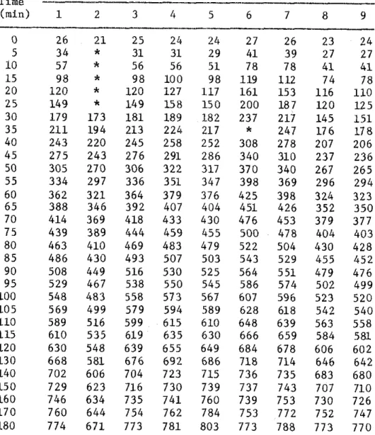
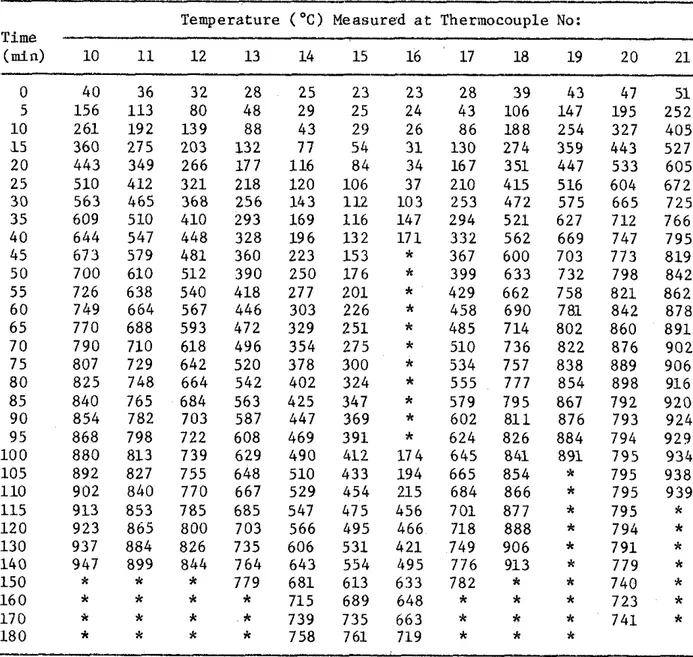
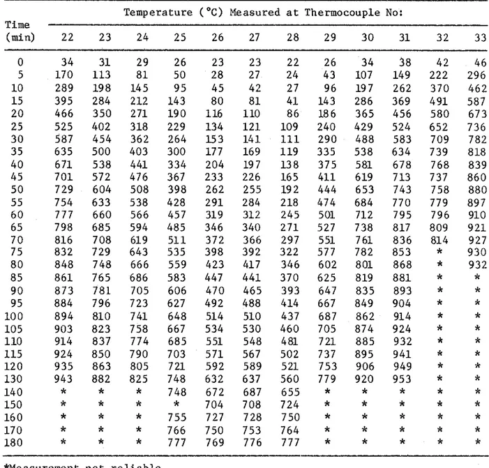
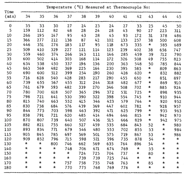
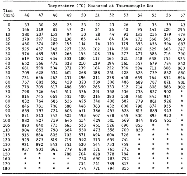
I n Table 2, t h e s t e e l temperatures a r e given f o r v a r i o u s times. The t e m p e r a t u r e s measured i n t h e c o n c r e t e s e c t i o n s a r e g i v e n i n T a b l e s 3A-D.
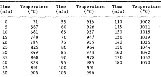
Table 4 g i v e s t h e average f u r n a c e temperature, and Tdble 5, t h e measured a x i a l d e f o r m a t i o n of t h e column, f o r v a r i o u s t i m e s d u r i n g t h e
t e s t . A f t e r 3 hours t h e column buckled and t h e test was t e r m i n a t e d . F i g u r e 9 shows t h e column i n t h e f u r n a c e chamber a f t e r t h e t e s t .
DISCUSSION OF RESULTS
Using t h e method d e s c r i b e d i n r e f e r e n c e 9, t h e temperatures of t h e main r e i n f o r c i n g s t e e l , and t h e t e m p e r a t u r e s a t v a r i o u s d e p t h s i n t h e c o n c r e t e s e c t i o n s have been c a l c u l a t e d . For t h e r e i n f o r c i n g s t e e l , t h e temperature a t t h e c e n t e r had been chosen a s r e p r e s e n t a t i v e of t h e average temperature of t h e s t e e l . This temperature h a s been p l o t t e d i n Fig. 10 a s a f u n c t i o n of time. It i s compared w i t h t h e a v e r a g e
temperatures o b t a i n e d from measurements on two r e i n f o r c i n g b a r s d u r i n g t h e t e s t . These measurements were ntade w i t h thermocouples No. 3 and 9 l o c a t e d o p p o s i t e each o t h e r w i t h r e s p e c t t o t h e c e n t e r of one b a r , and w i t h thermocouples No. 4 and 8, l o c a t e d o p p o s i t e each o t h e r on a n o t h e r bar (Fig. 6 ) . The comparison between measured average s t e e l
temperatures and t h e t e m p e r a t u r e s i n t h e c o n c r e t e a t t h e c e n t e r of t h e s t e e l , c a l c u l a t e d according t o t h e method d e s c r i b e d i n r e f e r e n c e 9, shows a good agreement between measured and c a l c u l a t e d temperatures.
The temperature measured on t h e s t e e l by t h e i n d i v i d u a l
thermocouples a r e shown i n Fig. 11. The d i f f e r e n c e i n temperature between two o p p o s i t e p o i n t s of t h e bar
i s
r e l a t i v e l y small.I n Fig. 12, t h e temperatures shown a r e measured a l o n g a c e n t e r l i n e i n t h e c o n c r e t e s e c t i o n a t v a r i o u s depths and column h e i g h t s .
I n Fig. 1 3 temperatures c a l c u l a t e d f o r t h r e e d e p t h s a r e compared w i t h t h e a v e r a g e of t h e t e m p e r a t u r e s measured a t t h r e e h e i g h t s a l o n g t h e c e n t e r l i n e of t h e column.
I n Fig. 14 a s i m i l a r comparison i s made f o r t h e temperatures a l o n g t h e d i a g o n a l of t h e column s e c t i o n .
The comparisons show a good agreement between measured and c a l c u l a t e d c o n c r e t e temperatures.
1. Standard Practice for Petrographic Examination of Aggregates for Concrete, (1979). ASTM C295-79, American Society for Testing and Materials, Philadelphia.
2. Standard Specification for Deformed and Plain Bullet-Steel Bars for Concrete Reinforcement, (1980). ASTM A615-80, American Society for Testing and Materials, Philadelphia.
3. Monfore, G.E. (1962). A Small Probe-Type Gauge for Measuring Relative Humidity. Journal of the PCA Research and Development Laboratories, Vol. 5, No. 2.
4.
Reinforcing Steel Welding Code, (1975). AWS-D12.1-75, American Welding Society, Manlius, NY.5. Lie, T.T. (1980). New Facility to Determine Fire Resistance of Columns, Canadian Journal of civil Engineering, Vol.
7,
No. 3. 6. Standard Methods of Fire Tests of Building Construction andMaterials, (1979). ANSI/ASTM E119-79, American Society for Testing and Materials, Philadelphia.
7. Standard Methods of Fire Endurance Tests of Building Construction and Materials, (1980). ULC-S10141980, Underwriters' Laboratories of Canada, Scarborough, Ontario.
8. Lie, T.T. and Harmathy, T.Z. (1972). A Numerical Procedure to Calculate the Temperature of Protected Steel Columns Exposed to Fire, Fire Study No. 28, Division of Building Research, National Research Council Canada, Ottawa, NRCC 12535.
9. Lie, T.T., Allen, D.E., Lin, T.D. and Abrams, M.S. Fire Resistance of Reinforced Concrete Columns, Division of Building Research, National Research Council Canada, Ottawa, to be published.
TABLE 1 PETROGRAPHY OF SAND AND GRAVEL USED AS AGGREGATE
Composition of Sieve Fraction, Percent on Sieve of Size Indicated Percent
Component Passing
19 mn 12.5 mm 9.5 mm 6mm No. No. No. NO. No. No. No. through
4 8 16 30 50 100 200 No. 200 Granite 37.9 32.9 25.5 31.3 27.0 27.6 12.3 7.4 1.9 4.4 0.6
-
Quartzite 21.6 29.2 34.8 24.6 24.5 20.0 12.3 12.6 10.9 3.1 2.2--
Quartz 6.3 3.1 4.9 4.8 5.5 18.8 52.2 62.0 73.1 79.5 74.2 92.0 cherta 10.8 7.0 5.2 8.1 9.8 5.9 7.7 3.5 2.0 0.8 2.8 2.0 Sandstone-Quartz Conglomerate 1.9 0.8 3.1 5.1 5.5 8.3--
--
--
--
--
--
Rhyolite-Dacite 13.9 6.2 2.2 5.1 7.2 4.1 0.8 2.6 1.6 0.8 0.9--
Feldspar-
-
-
-
-
-
1.3 5.0 6.6 5.0 10.8 4.0 Diorite 1.9 1.4 3.1 1.8 1.2-
--
-
-
-
--
~ r a y w a c k e ~ 1.3 9.5 5.8 5.4 4.3 6.5 2.3 1.5 0.3--
0.6--
Gneiss-Schist 2.5 5.1 10.5 9.3 7.5 4.1 6.4 1.8 0.9 1.1 0.6--
Basalt 1.9 4.5 4 .O 3.9 6.9 3.2 2.6 2.4 0.7-
0.3--
Mist. Igneous Rocks and Opaque Minerals-
0.3 0.9 0.6 0.6 1.5 2.1 1.2 2.0 5.3 7.0 2.0Particle Shape 19 to 6 mm (X) No. 4 to No. 16 (%) No. 3 0 to No. 200 (X)
Subrounded to rounded 30 20 10
Suhrounded to subangular 40 40 40
Angular 30 40 50
a"lronstone," made up of jasper and hematite, is included in the chert classification. b~ncludes metagraywacke.
%'he miscellaneous igneous rocks were severely altered and positive identification was impossible. The opaque minerals occurred
TABLE 2 MEASURED STEEL TEMPERATURES
T e m p e r a t u r e ("C) Measured a t Thermocouple No:
Time
-
(min) 1 2 3 4 5 6 7 8 9 P 0 26 2 1 2 5 24 24 27 26 23 24 5 3 4*
3 1 3 1 29 41 3 9 27 27 1 0 57*
56 56 5 1 78 7 8 4 1 4 1 1 5 9 8*
9 8 1 0 0 9 8 119 112 74 78 2 0 1 2 0*
120 127 117 1 6 1 1 5 3 116 1 1 0 2 5 1 4 9*
1 4 9 1 5 8 1 5 0 200 187 1 2 0 1 2 5 3 0 179 1 7 3 181 189 182 237 217 1 4 5 1 5 1 3 5 2 1 1 1 9 4 213 224 217*
247 176 1 7 8 40 243 220 245 258 252 3 0 8 278 207 206 4 5 275 2 4 3 276 291 286 340 310 237 236 50 305 270 306 322 317 3 7 0 340 267 265 5 5 3 3 4 297 336 351 347 3 9 8 369 296 294 6 0 362 3 2 1 364 379 376 425 3 9 8 324 3 2 3 6 5 3 8 8 3 4 6 392 407 404 451 426 352 3 5 0 70 414 369 418 4 3 3 430 476 4 5 3 379 377 7 5 439 389 444 459 455 500 478 404 4 0 3 8 0 463 410 469 4 8 3 479 522 504 430 4 2 8 8 5 486 430 4 9 3 507 5 0 3 5 4 3 529 4 5 5 4 5 2 9 0 508 449 516 5 3 0 5 2 5 564 5 5 1 479 476 9 5 529 467 538 550 545 586 574 502 499 1 0 0 548 4 8 3 558 5 7 3 567 607 596 5 2 3 5 2 0 1 0 5 569 499 579 594 589 6 2 8 618 542 5 4 0 1 1 0 589 516 599 615 610 6 4 8 639 563 5 5 8 1 1 5 610 5 3 5 619 6 3 5 6 3 0 666 659 584 581 120 6 3 0 5 4 8 639 6 5 5 649 684 6 7 8 606 602 1 3 0 6 6 8 581 6 7 6 6 9 2 686 718 714 646 642 140 702 606 704 723 715 736 735 683 680 1 5 0 729 6 2 3 716 7 3 0 739 737 7 4 3 707 710 160 746 634 735 7 4 1 760 739 753 730 726 1 7 0 7 6 0 6 4 4 754 762 784 7 5 3 772 752 747 1 8 0 774 6 7 1 773 7 8 1 8 0 3 7 7 3 788 7 7 3 7 7 0-
"Measurement n o t r e l i a b l eTABLE 3A CONCRETE TEMPERATURES MEASURED WITH THERMOCOUPLES I N FKAME A
Temperature (OC) Measured a t Thermocouple No: Time (min) 10 11 12 13 14 15 16 17 18 19 20 21 0 40 36 32 28 5 156 113 80 48 10 261 192 139 88 1 5 360 275 203 132 20 443 349 266 177 2 5 510 412 321 218 30 563 465 368 256 35 609 510 410 293 4 0 644 547 448 328 45 673 579 481 360 5 0 700 610 512 390 5 5 726 638 540 418 60 749 664 567 446 65 770 688 593 4 7 2 70 790 710 618 496 75 807 729 642 520 8 0 825 748 664 542 85 840 765 684 563 9 0 854 782 703 587 9 5 868 798 722 608 10 0 880 813 739 629 105 892 827 755 648 110 902 840 770 667 115 913 853 785 685 120 923 865 800 703 130 937 884 826 735 14 0 947 899 844 764 150 x
*
*
779 16 0*
*
x x 17 0*
*
*
*
180*
x*
k-
*Measurement n o t r e l i a b l eTABLE 3B CONCRETE TEMPERATURES MEASURED WITH THERMOCOUPLES I N FRAME B
T e m p e r a t u r e ("C) Measured a t Thermocouple No: Time
(min) 22 2 3 24 25 26 27 28 29 3 0 31 32 33
TABLE 3C CONCRETE TEMPERATURES MEASURED WITH THERMOCOUPLES I N FRAME C
Temperature ("C) Measured a t 'I'hermowuple No: Time (min) 3 4 35 36 37 38 39 4 0 41 42 43 4 4 45 0 35 3 3 30 27 2 4 2 3 2 4 27 3 3 25 45 5 0 5 1 5 9 1 1 2 82 48 28 2 4 2 8 43 9 0 27 223 3 1 1 1 0 2 6 6 1 9 5 147 9 5 43 28 45 9 3 1 7 2 31 3 7 8 4 8 6 1 5 366 277 212 1 3 8 87 42 1 0 2 133 257 38 5 0 0 6 0 8 2 0 4 4 6 351 2 7 6 1 8 5 117 9 5 118 6 7 3 335
*
5 8 5 6 8 9 25 509 410 329 227 1 2 1 1 1 4 123 239 402 38 6 5 6 7 4 7 3 0 559 4 6 0 374 2 6 6 1 4 3 111 1 4 6 2 8 5 4 5 9 3 9 712 7 9 0 3 5 6 0 0 502 414 303 1 6 8 1 1 4 172 3 2 6 508 4 9 755 8 2 3 4 0 6 3 4 5 3 8 450 337 1 9 6 1 3 6 2 0 0 363 5 4 8 5 0 7 8 5 8 4 4 45 6 6 3 569 482 369 225 1 6 4 2 3 0 395 585*
8 0 9 8 6 3 5 0 6 9 0 6 0 0 512 3 9 9 2 5 4 1 9 0 2 6 0 426 6 2 0*
8 3 2 8 8 2 5 5 716 6 2 8 540 428 283 217 290 455 6 5 0*
8 5 1 897 6 0 7 3 9 6 5 5 567 455 312 244 318 482 677*
8 6 9 910 6 5 7 6 1 6 7 9 593 482 339 2 7 0 3 4 6 508 7 0 2*
8 8 5 9 2 4 7 0 7 8 0 7 0 0 618 507 365 296 3 7 2 531 7 2 5*
8 9 8 9 3 5 7 5 7 9 8 7 2 1 6 4 1 5 3 0 3 9 0 3 2 2 3 9 8 5 5 4 7 4 5*
910 9 4 4 8 0 815 7 4 0 6 6 3 5 5 2 415 3 4 6 4 2 3 579 7 6 4*
9 2 0 9 5 2 8 5 8 3 0 7 5 8 6 8 4 576 4 3 9 369 447 6 0 2 7 8 2*
9 2 8 957 9 0 8 4 4 7 7 5 7 0 3 5 9 8 4 6 3 3 9 2 471 6 2 5 7 9 9*
9 3 5 9 6 3 9 5 858 7 9 1 7 2 1 6 2 0 485 414 4 9 4 646 815*
942 9 7 0 1 0 0 8 7 0 8 0 7 7 3 9 6 4 0 507 4 3 6 515 6 6 6 8 2 9*
9 4 2 9 7 5 1 0 5 882 8 2 1 7 5 5 660 527 4 5 9 5 3 5 6 8 4 8 4 3 5 2*
9 8 0 1 1 0 8 9 3 8 3 4 7 7 1 6 7 9 5 4 6 4 8 0 5 5 3 7 0 2 8 5 5 5 3*
9 8 4 1 1 5 9 0 3 8 4 5 7 8 5 697 569 5 0 1 575 7 1 9 867 5 3*
986 1 2 0 9 0 9 8 5 2 7 9 6 715 5 9 8 521 5 9 6 7 3 5 8 7 8 5 4*
*
1 3 0*
*
8 0 0 7 4 6 662 569 6 3 5 7 6 4 896 5 4*
*
1 4 0*
x*
7 4 8 7 0 6 671 6 7 4 7 6 9*
5 5*
x 1 5 0 x*
x*
7 2 4 7 2 5 7 0 4 7 3 7*
8 0*
x 1 6 0*
x x*
7 3 9 7 3 9 7 2 5 7 4 4*
k*
x 17 0*
x*
757 7 5 8 7 5 5 7 4 8 7 6 3*
8 5*
*
1 8 0*
*
*
7 7 0 7 7 5 7 6 8 7 6 9 7 7 6*
*
*
*
*Measurement n o t r e l i a b l eTABLE 3D CONCRETE TEMPERATURES MEASURED WITH THERMOCOUPLES I N FRAME D
Temperature ('C) Measured a t Thermocouple No: Time
(min) 4 6 47 4 8 4 9 50 51 52 5 3 5 4 55 56 57
TABLE 4 AVERAGE FURNACE TEMPERATURE
- - -- - - - --
Time Temperature Time Temperature rime Temperature ( m i d ("C) ( m i d ("C) ( m i d ("C)
TABLE 5 MEASURED AXIAL DEFORMATION OF COLUMN
Defor- Def or- Defor-
Time mation Time mation Time mation ( m i d (mm) ( m i d (mm) (min) (mm)
-
s i g n i n d i c a t e s c o n t r a c t i o n of column p a s t i n i t i a l s t a r t i n g p o s i t i o nI-
/
A G G R E G A T E C O A R S Em m
m m
m m
S T A N D A R D S I Z E O F S Q U A R E M E S H S I E V E F I G U R E 1
2 5 mrn T H I C K P L A T E 20 M B A T H I C K P L A T E F I G U R E 2 M A I N R E I N F O R C I N G B A R S
TIC
S E C T I O N A - A
TIC FRAME
vi
O N BACK
\
TIC FRAME C
ON FRONT
-S E C T I O N B - B
TIC FRAME
D
S E C T I O N C - C
-
F I G U R E
3
L A Y O U T O F T H E R M O C O U P L E F R A M E S
TIC FRAME
H
=3810
rnrn
TIC FRAME
F I G U R E 4
L O C A T I O N A N D N U M B E R S OF T H E R M O C O U P L E S I N A Q U A R T E R S E C T I O N O F 2 0 3
x
2 0 3 rnm C O L U M N48
m m
COVER TO M A I NT,c
4,
5,8$;~;o~c~~~
B A R 4 2 0 M BAR 203mm?
IJLTIC
1,2,3,9 203m m
5 3 3 x 5 3 3 ~ 25 mm- THICK STEEL PLATE?F I G U R E 5
T H E R M O C O U P L E S O N R E I N F O R C I N G B A R S
F I G U R E 6
FIGURE 7
T O P V I E W 1, 2 C O L U M N F U R N A C E 3 , 4 5 ' 6 C H A M B E R 7. 8 I I D O O R ( E A S T S I D E 1 F I G U R E 8 L O C A T I O N A N D N U M B E R S O F T H E R M O C O U P L E S I N C O L U M N F U R N A C E C H A M B E R
FIGURE 9
t
CALCULATED-,,
0 100 2 0 0 T I M E , r n i n F I G U R E 10 C A L C U L A T E D A N D M E A S U R E D A V E R A G E T E M P E R A T U R E S O F M A I N R E I N F O R C I N G E A R S T I M E , rnin F I G U R E 11 T E M P E R A T U R E S M E A S U R E D O N M A I N R E i N F O R C l N G B A R St
- MID-HEIGHT & 314 HEIGHT-
- --
-
- - 314 HEIGHT1
T I M E , m i n F I G U R E 12 T E M P E R A T U R E S M E A S U R E D I N C O N C R E T E S E C T I O N A L O N G C E N T R E L I N E A T V A R I O U S D E P T H S A N D C O L U M N H E I G H T S 1 0 0 0 I I CALCULAED1
T I M E , m i n F I G U R E 1 3 C O N C R E T E T E M P E R A T U R E S I N S E C T I O N A L O N G C E N T R E L I N E A T V A R I O U S D E P T H S1000 I