HAL Id: hal-00939406
https://hal.archives-ouvertes.fr/hal-00939406
Submitted on 11 May 2021
HAL is a multi-disciplinary open access
archive for the deposit and dissemination of sci-entific research documents, whether they are pub-lished or not. The documents may come from teaching and research institutions in France or abroad, or from public or private research centers.
L’archive ouverte pluridisciplinaire HAL, est destinée au dépôt et à la diffusion de documents scientifiques de niveau recherche, publiés ou non, émanant des établissements d’enseignement et de recherche français ou étrangers, des laboratoires publics ou privés.
Silicate liquid-carbonatite liquid transition along the
melting curve of model, vapor-saturated peridotite in
the system CaO-MgO-Al2O3-SiO2-CO2 from 1.1 to 2
GPa
Shantanu Keshav, Gudmundur H. Gudfinnsson
To cite this version:
Shantanu Keshav, Gudmundur H. Gudfinnsson. Silicate liquid-carbonatite liquid transition along the melting curve of model, vapor-saturated peridotite in the system CaO-MgO-Al2O3-SiO2-CO2 from 1.1 to 2 GPa. Journal of Geophysical Research, American Geophysical Union, 2013, 118 (7), pp.3341-3353. �10.1002/jgrb.50249�. �hal-00939406�
Silicate liquid-carbonatite liquid transition along the melting
curve of model, vapor-saturated peridotite in the system
CaO-MgO-Al
2O
3-SiO
2-CO
2from 1.1 to 2 GPa
Shantanu Keshav1,2and Gudmundur H. Gudfinnsson3
Received 18 January 2013; revised 31 May 2013; accepted 12 June 2013; published 19 July 2013.
[1] Solidus phase relations of carbon dioxide-saturated (CO2vapor) model peridotite in the system CaO-MgO-Al2O3-SiO2-CO2in the 1.1–2.1 GPa pressure range are reported. The solidus has a positive slope in pressure-temperature (PT) space from 1.1 to 2 GPa. Between 2 and 2.1 GPa, the melting curve changes to a negative slope. From 1.1 to 1.9 GPa, the liquid, best described as CO2-bearing silicate liquid, is in equilibrium with forsterite, orthopyroxene, clinopyroxene, spinel, and vapor. At 2 GPa, the same crystalline phase assemblage plus vapor is in equilibrium with two liquids, which are silicate and carbonatitic in composition, making the solidus at 2 GPa PT invariant. The presence of two liquids is interpreted as being due to liquid immiscibility. Melting reactions written over 1.1–1.9 GPa are peritectic, with forsterite being produced upon melting, and the liquid is silicate in composition. Upon melting at 2.1 GPa, orthopyroxene is produced, and the liquid is carbonatitic in composition. Hence, the invariance between 1.9 and 2.1 GPa is not only the reason for the dramatic change in the liquid
composition over an interval of 0.2 GPa, but the carbonated peridotite solidus ledge itself most likely appears because of this PT invariance. It is suggested that because carbonatitic liquid is produced at the highest solidus temperature at 2 GPa in PT space in the system studied, such liquids, in principle, can erupt through liquid immiscibility, as near-primary magmas from depths of approximately 60 km.
Citation: Keshav, S., and G. H. Gudfinnsson (2013), Silicate liquid-carbonatitic liquid transition along the melting curve of model, vapor-saturated peridotite in the system CaO-MgO-Al2O3-SiO2-CO2from 1.1 to 2 GPa, J. Geophys. Res. Solid
Earth, 118, 3341–3353, doi:10.1002/jgrb.50249.
1. Introduction
[2] In the context of melting phase relations of carbonated
peridotite at elevated pressure-temperature (P-T/PT) condi-tions, the so-called ledge at a pressure of ~2.5–3 GPa is a very prominent feature in the solidus topology of carbonated peri-dotite [White and Wyllie, 1992, and references therein; Dalton and Presnall, 1998]. The ledge has previously been interpreted to be caused by the appearance of crystalline carbonate (or simply carbonate from now on) at high pressures by reaction with carbon dioxide vapor (CO2vapor or simply
vapor from this point onward) on the high-pressure side of the carbonated peridotite phase diagram. Once this vapor-carbonate reaction goes to completion, the melting temper-ature of carbonated peridotite, relative to the solidus temperature of dry peridotite, decreases, by ~200–250°C.
The carbonated peridotite ledge wasfirst reported in the sys-tem CaO-MgO-SiO2-CO2 (CMS-CO2) [Eggler, 1973,
1974, 1975, 1976; Wyllie and Huang, 1976a; reviewed in Dalton and Presnall, 1998; Moore and Wood, 1998; Luth, 1999] and withstands the addition of alumina (Al2O3) to
the system CMS-CO2 [Dalton and Presnall, 1998;
reviewed in Luth, 1999; Gudfinnsson and Presnall, 2005]. In both the systems CMS-CO2 and CaO-MgO-Al2O3
-SiO2-CO2(CMAS-CO2), the intersection of the carbonated
peridotite solidus with that of the subsolidus vapor-carbon-ate boundary line genervapor-carbon-ates PT invariance, at which vapor, carbonate, and liquid coexist with model mantle peridotite. This PT-invariant point, depending upon the identity of the system (CMS-CO2versus CMAS-CO2), occurs in the
pressure range of 2.4–3 GPa.
[3] The dramatic drop in temperature of melting along the
ledge has been attributed to a conspicuous change in the liquid composition at the solidus—from being silicate with <7–8 wt % dissolved CO2 at about 2–2.6 GPa to carbonatitic with
approximately 40 wt % CO2at pressures greater than about
2.6 GPa. On this aspect, Wyllie and coworkers claimed that this change in the liquid composition happens where the subsolidus, PT-univariant vapor-crystalline carbonate bound-ary line intersects the PT-univariant solidus ledge [White and Wyllie, 1992, and references therein; reviewed in Dalton and Presnall, 1998; Moore and Wood, 1998; Luth, 1999;
1
Bayerisches Geoinstitut, Universität Bayreuth, Bayreuth, Germany. 2Geosciences Montpellier, CNRS and UMR 5243, University of Montpellier 2, Montpellier, France.
3Iceland GeoSurvey, Reykjavik, Iceland.
Corresponding author: S. Keshav, Geosciences Montpellier, CNRS UMR 5243, University of Montpellier 2, Montpellier, France. ([email protected])
©2013. American Geophysical Union. All Rights Reserved. 2169-9313/13/10.1002/jgrb.50249
Gudfinnsson and Presnall, 2005; Luth, 2006]. Hence, contrary to Eggler and coworkers [Eggler, 1976; Eggler et al., 1976; Mysen et al., 1976] who viewed the change in liquid compo-sitions along the ledge due primarily to the solubility of vapor in the liquid, Wyllie and coworkers [White and Wyllie, 1992, and references therein] emphasized that such a treatment is not appropriate because of the radical change in the liquid composition. The subject of liquid composi-tions along the ledge (~2–3 GPa ) has been, without resolu-tion, fairly extensively debated in the published literature [Eggler, 1976; Eggler et al., 1976; Eggler, 1978, 1987a, 1987b; Wyllie and Huang, 1976a, 1976b; Wyllie, 1987a, 1987b]. However, until recently, microprobe analyses of liquid compositions along the ledge were not reported.
[4] Previously, the melting reactions along the ledge in
the system CMAS-CO2are suggested to be of peritectic type,
forsterite + clinopyroxene (cpx) + vapor + garnet = orthopyroxene (opx) + liquid [Dalton and Presnall, 1998]. Ghosh et al. [2008] and Novella and Keshav [2010] experimentally mapped the ledge and determined the melting phase relations of model, vapor-bearing peridotite in the system CMAS-CO2.
These two recent studies report that the liquids all along and around the PT-univariant solidus ledge, over 2.1–3 GPa, are carbonatitic (with about 38–44 wt % dissolved CO2), and also
confirm the peritectic nature of the melting reactions, as indi-cated by Dalton and Presnall [1998].
[5] The intent of the present work is to reexamine the
debate between Eggler and Wyllie on the liquid composi-tions (silicate versus carbonatitic), along the melting curve of model, vapor-bearing peridotite. In so doing, we attempt to clarify the melting phase relations of model, vapor-bearing peridotite by approaching the ledge from the low-pressure side over the pressure range of 1.1–2 GPa. The present exper-imental study has implications for carbonatite-related meta-somatism, the possibility that carbonatites might erupt as near-primary magmas, and the origin of carbonatitic and silicate liquids as due to liquid immiscibility. This work builds upon phase relations of model carbonated peridotite at similar or higher pressures [Dalton and Presnall, 1998; Gudfinnsson and Presnall, 2005] and in the vapor-free sys-tem CaO-MgO-Al2O3-SiO2(CMAS) [Presnall et al., 1979;
Gudfinnsson and Presnall, 1996; Liu and Presnall, 2000]. However, the influence of alkalies (Na2O and K2O), water
(H2O), and iron oxide (FeO) on the melting phase relations
is unknown at the moment and needs to be systematically explored. Notwithstanding the above lack of knowledge, the use of low-variance model systems (as in CMAS-CO2)
offers yet another advantage in that a particular starting com-position can be fashioned such as to maximize the amount of liquid (or any other phase) in the run products. However, this philosophy is advantageous only if the experiments defining melting phase relations contain the required phases, which, in the present case, are isobaric invariant assemblages. There would be instances (see later) where experiments do not contain the required assemblages at prechosen conditions of pressure and temperature. Hence, the solidus is defined as a curve in PT space, below which melt is absent—a definition that applies strictly to natural, multicomponent systems. In our case, a bulk composition was prepared to maximize the amount of liquid, without modifying the melting phase relations or phase compositions. We adopted this strategy so that liquid compositions can be retrieved using the elec-tron microprobe. Therefore, in the melting phase relations reported here, at a fixed pressure, the solidus is ideally defined as containing an invariant assemblage. In case where such conditions are not met, bracketing assemblages provide temperature estimates for the invariant solidus at a particular pressure. In an ideal case, melt will always be present on the low-temperature side of the melting curve, since starting compositions are tailored to yield large amount of melt. However, sometimes, melt might not be present on the low-temperature side of the bracketing phase assemblage, but the governing principle remains the same. In this manner, the solidus is rigorously determined.
[6] To illustrate the intent of the present study graphically,
we focus on Figure 1 (modified after Dalton and Presnall [1998] and Gudfinnsson and Presnall [2005]), which shows solidi curves for volatile-free (CaO-MgO-Al2O3-SiO2
(CMAS)) and carbonated (CMAS-CO2) peridotite. The
dashed curve shows the estimated location of the carbonated peridotite solidus, along which vapor coexists with liquid and a crystalline phase assemblage. That is, along the dashed curve, saturation with respect to CO2occurs. Shown with
arrows are two PT-invariant points, C (~0.9 GPa) and A (~2.4–2.5 GPa), created by the intersection of the subsolidus anorthite-spinel (an-sp) and spinel-garnet (sp-gt) peridotite PT-univariant boundary curves with the carbonated perido-tite PT-univariant solidus curve (dashed). These invariant Figure 1. Solidus curves for model, volatile-free
(CaO-MgO-Al2O3-SiO2CMAS) and CO2-bearing (CMAS-CO2)
peridotite shown with arrows as “CO2-free peridotite
solidus” and “Carbonate-bearing peridotite solidus,” respectively. The dashed curve shows the estimated loca-tion of the carbonated peridotite solidus, along which CO2
vapor (vapor) coexists with liquid and crystalline phase assemblage (modified after Dalton and Presnall [1998] and Gudfinnsson and Presnall [2005]). In the system CMAS-CO2, the subsolidus assemblages, below the dashed
melting curve, consist of an-pdt + vapor (forsterite + opx + cpx + anorthite + vapor), sp-pdt + vapor (forsterite + opx + cpx + spinel + vapor), and gt-pdt + vapor (forsterite + opx + cpx + garnet + vapor). The dashed curve straddling point C and the pressure datum of 2 GPa is the focus of the present study. The abbreviations are as follows: an—anorthite; opx— orthopyroxene; cpx—clinopyroxene; pdt—peridotite; sp— spinel; and gt—garnet. Further details are in section 1.
points consist of the assemblages forsterite + opx + cpx + anorthite + spinel + vapor + melt and forsterite + opx + cpx + spinel + garnet + vapor + melt, respectively. The carbonate ledge (between points A and B) is a part of this dashed curve and terminates at point B. Point B marks the transition from vapor to carbonate-bearing peridotite with melt and is hence another PT-invariant point consisting of forsterite + opx + cpx + garnet + vapor + carbonate + melt. Therefore, along the PT-univariant curve between points C and B, the phase assem-blage consists of either forsterite + opx + cpx + spinel + vapor + melt (C to A) or forsterite + opx + cpx + garnet + vapor + melt (A to B). Point F is yet another PT-invariant point consisting of forsterite + opx + cpx + garnet + dolomite + magnesite + melt, signifying the onset of transformation of dolomite (or, to be precise, magnesian calcite [Dalton and Presnall, 1998]) to magnesite in model carbonated peridotite.
[7] Melting phase relations of model carbonated peridotite,
including that of the grey region in thisfigure, are known only from pressure greater than 3 GPa (up to 7–8 GPa [Dalton and Presnall, 1998; Gudfinnsson and Presnall, 2005]). A note of caution is perhaps needed here: The dashed curve in Figure 1 first appeared in Dalton and Presnall [1998]; however, neither Dalton and Presnall [1998] nor the subsequent studies that have referred to this curve [Luth, 1999; Gudfinnsson and Presnall, 2005; Luth, 2006] supply information on as to how this dashed curve was sketched to start with. Hence, it would appear that this dashed curve (including point B) is a theoretical construct drawn to be in agreement with other experimental results (see caption of Figure 1). Therefore, on this basis, we have directly taken the form of the dashed curve in Figure 1 from the aforementioned studies. Gudfinnsson and Presnall [2005] redetermined the position of point F and found it to be in excellent agreement with the one originally reported in Dalton and Presnall [1998]. It is again emphasized that the points F, B, A, and C have all been directly taken from Dalton and Presnall [1998] and Gudfinnsson and Presnall [2005]. Two PT-invariant points marked D and E (shown with arrows) are created by the intersection of the subsolidus anorthite-spinel and spinel-garnet peridotite boundary curves with the PT-univariant solidus of model, vapor-free peridotite and consist of forsterite + opx + cpx + anorthite + spinel + melt and forsterite + opx + cpx + spinel + garnet + melt, respectively. These two latter points have been taken from Presnall et al. [1979], Gudfinnsson and Presnall [1996], and Milholland and Presnall [1998]. A portion of the dashed curve approximately between PT-invariant point C and the pressure datum of 2 GPa is the focus of the present study.
2. Methods
[8] The experiments were conducted using the starting
mixture CMAS-CO2-1, whose nominal composition
(by weight) is as follows: CaO = 11.24, MgO = 31.96, Al2O3= 6.39, SiO2= 45.41, and CO2= 5.00. This starting
mixture, used in a recent experimental study [Gudfinnsson and Presnall, 2005], was prepared using a combination of shelf carbonate and oxides: CaCO3 (Alfa Aesar®,
99.998%), MgO (Alfa Aesar®, 99.998%), Al2O3 (Alfa
Aesar®, 99.998%), and SiO
2 (Aldrich®, 99.995%).
Magnesite from Oberdorf (Austria; generously supplied by Peter Ulmer, Zürich) provided all CO2 and some MgO.
This particular magnesite was used in the experimental work on the pseudobinary CaCO3-MgCO3by Buob et al.
[2006]. The silicate portion of the starting mixture CMAS-CO2-1 was prepared first as a glass. All the components
werefired in platinum (Pt) crucibles for at least 17–19 h in air—MgO, Al2O3, and SiO2at 1250°C and CaCO3at 400°
C. Pt crucibles that had not been previously utilized to dry either iron metal or iron oxides were used. To prepare the starting mixture,fired oxides and CaCO3were immediately
mixed in appropriate proportions and ground for at least 1 h under ethanol in an agate mortar. After drying under an in-frared (IR) heat lamp, this mixture, contained in a Pt cruci-ble, was decarbonated in air in a box furnace. To decarbonate, the temperature of the furnace was slowly ramped to 1000°C over 10 h and maintained at this temper-ature for approximately 6–7 h. After this step, the Pt crucible was taken out of the furnace and then almost imme-diately transferred to another high-temperature furnace to prepare glass. Silicate glass was prepared in air at 1650°C for about 3–4 h. To quench this liquid, the Pt crucible was partially immersed in an ice water bath, and the resulting glass was optically pure and transparent. This glass was finely ground for about 30–40 min, and using the same procedure, glassing was repeated once more. To ensure homogeneity, the silicate glass was reground for 1 h under ethanol in an agate mortar and then dried under an IR heat lamp for about 1 h. Finely ground magnesite was fired at 200–250°C in air in a Pt crucible for over 17 h. Silicate glass and magnesite were mixed and ground in an agate mortar under ethanol for another 1 h, and thefinal contents were poured in a glass vial and stored in a desiccator.
[9] All the experiments from 1.1 to 2 GPa were performed
in a traditional, three-post piston-cylinder device installed at Bayerisches Geoinstitut (Bayreuth); this apparatus has a maximum load of 250 t. Experiments employed half-inch talc-pyrex pressure cells with stepped graphite heaters. Pressure calibrations on the piston-cylinder apparatus were done using the anorthite-spinel (forsterite + opx + cpx + anor-thite + spinel + melt [Presnall et al., 1979]) and spinel-garnet (forsterite + opx + cpx + spinel + garnet + melt [Milholland and Presnall, 1998]) peridotite solidus transitions in the system CMAS. The precisions in temperature and pressure are estimated to be about ±10–15°C and ±0.5 kbar, respec-tively. In order to be as consistent as possible to the University of Texas at Dallas experimental data in the system CMAS, all the pressure calibrations and the reported experiments here were performed using the hot piston-out method.
[10] For all the experiments, Pt capsules were used, and
the final (after the run) capsule dimensions were approxi-mately 1.5 mm wide by 1.8 mm long. For all experiments, ~0.5–0.7 mg of the starting mixture, CMAS-CO2-1, was
loaded into a Pt capsule that had previously been annealed in air at 1000°C, sealed at one end by arc welding, boiled in dilute HCl (~30 min), ultrasonically cleaned in ethanol (10–15 min ), and fired again in air at 1000°C for 10 min. With the intent only to minimize temperature gradients, this little amount of starting mixture (~0.5–0.7 mg) surrounded with fairly decent lot of Pt metal (capsule) was used. Before assembling the pressure cell, the loaded capsule was dried in air at 175–200°C for over 14 h. The run temperature was mea-sured using type D (W75Re25/W97Re3) thermocouple wires
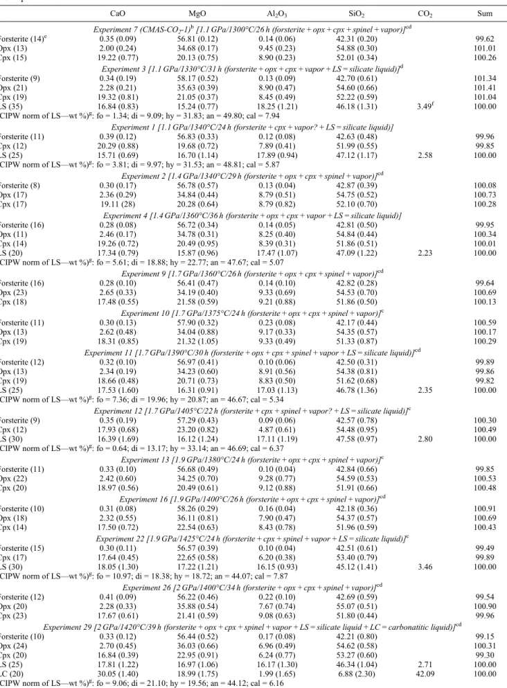
Table 1. Experimental Details, Run Products, and Electron Microprobe Analyses (in wt %) of Crystalline Phases and Quenched Liquids in the Experimentsa
CaO MgO Al2O3 SiO2 CO2 Sum
Experiment 7 (CMAS-CO2-1) b
[1.1 GPa/1300°C/26 h (forsterite + opx + cpx + spinel + vapor)]cd
Forsterite (14)e 0.35 (0.09) 56.81 (0.12) 0.14 (0.06) 42.31 (0.20) 99.62
Opx (13) 2.00 (0.24) 34.68 (0.17) 9.45 (0.23) 54.88 (0.30) 101.01
Cpx (15) 19.22 (0.77) 20.13 (0.75) 8.90 (0.23) 52.01 (0.34) 100.26
Experiment 3 [1.1 GPa/1330°C/31 h (forsterite + opx + cpx + vapor + LS = silicate liquid)]d
Forsterite (9) 0.34 (0.19) 58.17 (0.52) 0.13 (0.09) 42.70 (0.61) 101.34
Opx (21) 2.28 (0.21) 35.63 (0.39) 8.90 (0.47) 54.60 (0.66) 101.41
Cpx (19) 19.32 (0.81) 21.05 (0.37) 8.45 (0.49) 52.22 (0.59) 101.04
LS (35) 16.84 (0.83) 15.24 (0.77) 18.25 (1.21) 46.18 (1.31) 3.49f 100.00
(CIPW norm of LS—wt %)g: fo = 1.34; di = 9.09; hy = 31.83; an = 49.80; cal = 7.94
Experiment 1 [1.1 GPa/1340°C/24 h (forsterite + cpx + vapor? + LS = silicate liquid)]
Forsterite (11) 0.39 (0.12) 56.83 (0.33) 0.12 (0.08) 42.63 (0.48) 99.96
Cpx (12) 20.29 (0.88) 19.68 (0.72) 7.89 (0.41) 51.99 (0.55) 99.85
LS (25) 15.71 (0.69) 16.70 (1.14) 17.89 (0.94) 47.12 (1.17) 2.58 100.00
(CIPW norm of LS—wt %)g: fo = 3.81; di = 9.97; hy = 31.53; an = 48.81; cal = 5.87
Experiment 2 [1.4 GPa/1340°C/29 h (forsterite + opx + cpx + spinel + vapor)]cd
Forsterite (8) 0.30 (0.17) 56.78 (0.57) 0.13 (0.04) 42.87 (0.39) 100.08
Opx (17) 2.36 (0.29) 34.84 (0.44) 8.79 (0.51) 54.75 (0.52) 100.73
Cpx (17) 19.11 (28) 20.28 (0.64) 8.79 (0.82) 52.10 (0.70) 100.28
Experiment 4 [1.4 GPa/1360°C/36 h (forsterite + opx + cpx + vapor + LS = silicate liquid)]
Forsterite (16) 0.28 (0.08) 56.72 (0.34) 0.14 (0.05) 42.81 (0.50) 99.95
Opx (11) 2.46 (0.17) 34.78 (0.31) 8.25 (0.40) 54.84 (0.44) 100.34
Cpx (14) 19.26 (0.72) 20.49 (0.95) 8.39 (0.31) 51.86 (0.51) 100.01
LS (20) 17.34 (0.79) 15.87 (0.96) 17.47 (1.07) 47.09 (1.22) 2.23 100.00
(CIPW norm of LS—wt %)g: fo = 5.61; di = 18.88; hy = 22.77; an = 47.67; cal = 5.07
Experiment 9 [1.7 GPa/1360°C/26 h (forsterite + opx + cpx + spinel + vapor)]cd
Forsterite (16) 0.28 (0.10) 56.41 (0.47) 0.14 (0.10) 42.82 (0.28) 99.64
Opx (23) 2.65 (0.33) 34.19 (0.40) 9.33 (0.69) 54.53 (0.70) 100.69
Cpx (18) 17.48 (0.55) 21.58 (0.59) 9.21 (0.88) 51.86 (0.50) 100.13
Experiment 10 [1.7 GPa/1375°C/24 h (forsterite + opx + cpx + spinel + vapor)]c
Forsterite (11) 0.30 (0.13) 57.90 (0.32) 0.23 (0.08) 42.17 (0.44) 100.59
Opx (13) 2.62 (0.48) 34.04 (0.88) 9.17 (0.33) 54.35 (0.57) 100.17
Cpx (19) 18.31 (0.85) 21.32 (1.05) 9.33 (0.49) 51.33 (0.87) 100.29
Experiment 11 [1.7 GPa/1390°C/30 h (forsterite + opx + cpx + spinel + vapor + LS = silicate liquid)]cd
Forsterite (12) 0.32 (0.10) 56.97 (0.41) 0.10 (0.06) 42.50 (0.31) 99.89
Opx (13) 2.34 (0.19) 34.23 (0.60) 8.91 (0.56) 54.38 (0.81) 99.86
Cpx (19) 18.66 (0.48) 20.71 (0.73) 8.83 (0.50) 51.62 (0.68) 99.82
LS (25) 17.53 (1.60) 16.31 (0.91) 17.03 (1.13) 46.78 (1.36) 2.35 100.00
(CIPW norm of LS—wt %)g: fo = 7.36; di = 19.96; hy = 20.87; an = 46.67; cal = 5.34
Experiment 12 [1.7 GPa/1405°C/22 h (forsterite + cpx + spinel + vapor? + LS = silicate liquid)]c
Forsterite (9) 0.35 (0.19) 57.29 (0.43) 0.09 (0.06) 42.57 (0.78) 100.30
Cpx (12) 17.93 (0.68) 23.20 (0.82) 4.87 (0.61) 54.48 (0.95) 100.49
LS (30) 16.39 (1.69) 16.12 (1.24) 17.11 (1.19) 47.58 (0.97) 2.80 100.00
(CIPW norm of LS—wt %)g: fo = 0.64; di = 13.17; hy = 33.14; an = 46.69; cal = 6.37
Experiment 13 [1.9 GPa/1380°C/24 h (forsterite + opx + cpx + spinel + vapor)]c
Forsterite (11) 0.33 (0.10) 56.68 (0.49) 0.10 (0.04) 42.84 (0.66) 99.85
Opx (22) 2.42 (0.60) 34.25 (0.70) 9.28 (0.77) 54.59 (0.53) 100.53
Cpx (20) 18.97 (0.56) 20.49 (0.61) 9.12 (0.88) 51.91 (0.66) 100.48
Experiment 16 [1.9 GPa/1400°C/26 h (forsterite + opx + cpx + spinel + vapor)]cd
Forsterite (10) 0.31 (0.08) 58.26 (0.29) 0.16 (0.04) 42.18 (0.36) 100.91
Opx (18) 2.32 (0.55) 36.11 (0.81) 7.90 (0.47) 54.37 (0.57) 100.69
Cpx (14) 17.50 (0.72) 22.54 (0.63) 8.43 (0.78) 51.96 (0.59) 100.43
Experiment 22 [1.9 GPa/1425°C/24 h (forsterite + cpx + spinel + vapor + LS = silicate liquid)]c
Forsterite (15) 0.30 (0.11) 56.57 (0.39) 0.10 (0.04) 42.51 (0.61) 99.49
Cpx (17) 17.64 (0.45) 22.65 (0.58) 6.20 (0.38) 53.40 (0.79) 99.89
LS (30) 18.05 (1.30) 17.22 (1.21) 16.15 (0.93) 45.12 (1.41) 3.46 100.00
(CIPW norm of LS—wt %)g: fo = 10.97; di = 18.38; hy = 18.72; an = 44.07; cal = 7.87
Experiment 26 [2 GPa/1400°C/34 h (forsterite + opx + cpx + spinel + vapor)]cd
Forsterite (12) 0.41 (0.09) 56.22 (0.46) 0.22 (0.10) 42.69 (0.59) 99.54
Opx (20) 2.28 (0.33) 35.88 (0.54) 7.67 (0.74) 55.07 (0.51) 100.90
Cpx (23) 17.67 (0.61) 21.41 (0.59) 9.08 (0.63) 51.80 (0.44) 99.96
Experiment 29 [2 GPa/1420°C/39 h (forsterite + opx + cpx + spinel + vapor + LS = silicate liquid + LC = carbonatitic liquid)]cd
Forsterite (10) 0.33 (0.12) 56.44 (0.52) 0.17 (0.08) 42.21 (0.80) 99.15
Opx (24) 2.70 (0.45) 36.03 (0.66) 6.96 (0.49) 54.62 (0.58) 100.31
Cpx (20) 16.84 (0.39) 22.95 (0.91) 6.24 (0.77) 53.27 (0.60) 99.30
LS (25) 17.81 (1.22) 16.97 (1.06) 16.17 (1.30) 46.34 (1.04) 2.71 100.00
LC (20) 30.05 (1.40) 18.99 (1.75) 1.99 (1.65) 6.88 (2.30) 42.09 100.00
(0.25 mm thick; Omega®). In each experiment, a 0.5 mm thick
MgO disc (fired in air, just before an experiment, at 1000°C for 1 h) separated the thermocouple junction from the Pt cap-sule. Dense, four-bore alumina tubes were used to contain the thermocouple wires, and the temperatures reported in the manuscript are thermocouple readings. The effect of pressure on the thermocouple emf was ignored. Temperature was con-trolled to within ±1–2°C of the target value using a Eurotherm controller. To ensure near-anhydrous conditions during the ex-periments, all the cell parts (save talc-pyrex pressure cells, stepped graphite heaters, andfilled capsules) were fired in air at 1000°C in a box furnace for 1 h. Each experiment was kept at a target pressure and temperature condition for approximately 24 to 40 h (Table 1). Experiments were quenched by turning off the power supply to the stepped graphite heater, and decompression was carried out in ap-proximately 10–15 min.
[11] After each run, the capsule was recovered from the
pressure cell, mounted longitudinally in Petropoxy 154 resin, and ground and polished for optical and electron microprobe examination. As a precautionary measure, runs were polished under water-absent conditions, and to this end, the charges were polished in kerosene-based oil (Buehler®) on SiC grit
(240–1000) paper. Charges also had to be vacuum impregnated multiple times with resin (Petropoxy 154). After this step, regrinding of the charges was done on SiC grit (600–1000) pa-pers under kerosene-based oil (Buehler®), until a satisfactory
surface for oil-based diamond polishing (3–0.25 μm) was obtained. To establish the presence of free CO2vapor, some
Pt capsules (identified in Table 1) were punctured while im-mersed in ethanol. Upon perforation, bubbles rising toward the top of the beaker containing ethanol confirmed that va-por was a free phase during the experimental conditions.
[12] The experiments reported here were not reversed, and
hence, attainment of chemical equilibrium is not proven; we note that earlier studies in CO2-rich systems at elevated
temperature-pressure conditions (for instance, Irving and Wyllie [1975], Gudfinnsson and Presnall [2005], and Brooker and Kjarsgaard [2011]) have suggested very fast equilibration times, causing experiments as short as less than 1 h to achieve equilibrium. Further, lack of zoning in the crystalline phases in the experiments reported here is consis-tent with near-equilibrium conditions.
[13] The compositions of the crystalline phases and
quenched melt were determined by a wavelength-dispersive
electron microprobe analyzer (five-spectrometer JEOL-JXA-8200 Superprobe in Bayreuth) with an accelerating voltage of 15 kV and a 15 nA probe current (at the Faraday cup). Melt was analyzed using a beam diameter of 1–5 μm. The beam diameter was 1–2 μm for crystalline phases, and all the analyses were performed in a fixed spot mode. Analyses were reduced using the ZAF (Z - atomic number; A - absorption correction; F -fluorescence correction) correc-tion scheme, and the amount of CO2in the melt was
esti-mated by difference from microprobe totals. Concentrations of the rest of the four oxides (that is, CaO, MgO, Al2O3,
and SiO2) in the charges were measured using a combination
of forsterite, diopside, spinel, and enstatite standards.
3. Textural Observations of Experimental Charges
[14] From 1.1 to 1.9 GPa, the polished experimental charges
at subsolidus and supersolidus conditions have almost identical textural appearances. On this basis, a few representa-tive backscattered electron (BSE) images are shown in Figures 2–4. At a given contrast and brightness, forsterite is the darkest crystalline phase (Figures 2–4). It is euhedral in outline and occurs uniformly throughout the charge. In almost all the experimental charges, subsolidus or supersolidus, forsterite is quite frequently friable and has a tendency to fall out of a particular charge (Figure 2a). Forsterite does not occur as an inclusion in any other crystalline phase but hosts small grains of spinel (Figure 2b). Orthopyroxene is uniformly distributed throughout a particular charge and has a prismatic habit (Figure 2c). In places, it displays platy habit with the long dimension ranging between 10 and 15μm. Clinopyroxene, for a given set of conditions, is the brightest crystalline silicate phase (Figures 2c–2e) and is subhedral. Among all the crystalline phases, spinel has the highest relief and can easily be distinguished from other phases by its roughly cubic habit in polished sections (Figure 2b). More often than not, it is found as an inclusion in forsterite. Increased run duration seemingly does not influence spinel occurring in forsterite.
[15] The majority of experimental charges (see Table 1 for
further details) shown here are porous, features that we inter-pret to have developed in the presence of free CO2vapor; that
is, experiments were saturated with CO2vapor. As a result of
this high porosity, charges had to be vacuum impregnated in
Table 1. (continued)
CaO MgO Al2O3 SiO2 CO2 Sum
Experiment 30 [2 GPa/1425°C/24 h (forsterite + cpx + vapor? + LS = silicate liquid + LC = carbonatitic liquid)]
Forsterite (9) 0.29 (0.08) 56.94 (0.66) 0.11 (0.04) 42.63 (0.76) 99.97
Cpx (13) 16.64 (0.94) 23.38 (1.21) 6.38 (0.80) 53.72 (0.91) 100.10
LS (20) 18.34 (1.10) 14.41 (1.33) 14.50 (1.24) 44.28 (2.78) 8.47 100.00
LC (20) 24.26 (1.89) 16.02 (1.49) 6.96 (4.55) 9.37 (3.67) 43.39 100.00
(CIPW norm of LS—wt %)g: hy = 35.89; an = 37.44; qtz = 6.63; cor = 0.78; cal = 19.26 aVapor is assumed to be pure CO
2. b
In parentheses is the starting composition used in all the experiments tabulated here. c
Spinel in the experiments assumed stoichiometric. d
Presence of vapor in these experiments was confirmed by piercing open Pt capsules in ethanol. eThe number of analyses.
f
CO2in LS (silicate liquid) and LC (carbonatitic liquid) calculated by difference. g
Normative silicate liquid in wt %; fo—forsterite; di—diopside; hy—hypersthene; an—anorthite; cal—calcite; qtz—quartz; cor—corundum; opx— orthopyroxene; cpx—clinopyroxene. Charges wherein the presence of vapor is dubious are shown as “vapor?.” All the charges were not punctured under ethanol. Some charges have textural evidence for vapor (small rotund, elliptical, or round voids that are interpreted as vapor).
resin for at least 3–4 times—despite that this severe plucking occurs (Figures 3a–3c). Slightly oblate, elliptical, and rather rotund voids (Figures 2b, 2e, 2f, 3b, and 3d) latching onto the boundaries of other phases are interpreted as vapor. In places, such voids have roundish outlines (Figure 2b) but can also be quite elliptical (Figure 3b). Round voids are also seen when glass (Figure 3e) is present either interstitially (Figure 2e) or as segregated pools (Figures 2f and 3f). Voids interpreted as vapor can be distinguished from pluck (which can and does occur during the grinding and polishing of the charges) features, since the former tend to be regular in their form (for instance, rotund/elliptical), while the latter are highly irregular; vapor (interpreted) never forms an interconnected network and, in this manner, resembles the textures at subsolidus conditions in Watson and Brenan [1987] and Brenan and Watson [1988] and liquid-bearing experiments in Hammouda [2003]. Quenched silicate liquid (see later) is generally present as glass (labeled LS = silicate liquid; Figures 2f and 3f). Besides being interstitial (Figures 2e and 3e), glass is segregated from the main crys-talline matrix (Figures 2f and 3f).
[16] From 1.1 to 1.7 GPa, crystalline phases in the presence
of quenched silicate liquid seem to be free of quench overgrowths. However, at 1.9 GPa, clinopyroxene exhibits
substantial overgrowth features (Figures 3e and 3f). At 2 GPa, clinopyroxene has similar, if not more, quench overgrowths (Figure 4a) as at 1.9 GPa. Most significant, however, is the appearance at 2 GPa of a second melt that occurs only interstitially (Figures 4a–4d), along with clear silicate glass. This interstitial melt is carbonatitic (labeled LC = carbonatitic liquid; see later) in composition. Therefore, along with the crystalline phase assemblage and vapor, there are two liquids in this experimental charge, which make this experiment PT invariant. Unlike the silicate liquid (Figures 4e and 4f), the interstitial quenched liquid has a dendritic appearance (Figures 4a–4c). In polished sections, silicate glass and quenched carbonatitic melt are not in physical contact with each other, being separated by crystal-line (or quenched crystalcrystal-line) phases (Figure 4f). Run duration does not influence the eventual results of the experiments at 2 GPa. It could be claimed that one possible consequence of these apparent quench crystals is to produce the carbonatitic liquid by enriching the residual carbonate component of a prequench, silicate melt. The following observations suggest that this is unlikely: (a) If the precipita-tion of crystalline solid phases from the silicate liquid did indeed lead to the formation of residual carbonatitic liquid, then it begs the question as to why such a process would Figure 2. (a–f) Backscattered electron (BSE) images of subsolidus and supersolidus experimental charges
at 1.1 GPa (Table 1). (These experiments utilized the starting mixture CMAS-CO2-1.) Figures 2a–2c and 2d–2f
are from two runs at 1300 and 1330°C, respectively. Details are forsterite (fo), orthopyroxene (opx), clinopyroxene (cpx), spinel, CO2vapor (vapor), and silicate liquid (LS). The very bright area in the top left
occur only at 2 GPa and 1420°C, and not at 1.9 GPa (or for that matter, at pressures lower than 1.9 GPa) where only a single, silicate liquid is present, and (b) even in the absence of two crystalline phases, opx and spinel, at 2 GPa and 1425°C, silicate and carbonatitic liquids coexist with forsterite, cpx, and, perhaps, vapor (Table 1). One could, in addition, raise a concern that the presence of two texturally and compositionally distinct liquids at 2 GPa is due to introducing change(s) in the experimental protocol; again, that such could not have been the case is borne out by the fact that the experimental strategy adopted here was identical over the reported pressure and temperature range.
[17] Despite these arguments, it could still be claimed that
an assemblage consisting of two liquids plus crystalline phases and vapor is just a peculiarity of the specific starting mixture CMAS-CO2-1. (In fact, such an objection should
not even be raised because melting phase relations are inde-pendent of the starting mixture used.) Yet to alleviate such concern and to ensure that the experimental observations using the starting mixture CMAS-CO2-1 are reproducible
within uncertainty, a second starting mixture CMAS-CO2
-20 was prepared. The starting mixture CMAS-CO2-20 was
fashioned using the phase compositions obtained from utiliz-ing CMAS-CO2-1 (2 GPa/1420°C; Table 1) and the exact
same preparation procedures that went in making CMAS-CO2-1. Further, runs using the new starting composition,
CMAS-CO2-20, followed the exact same experimental
pro-cedure as the previous runs. Results obtained from the exper-iments using the starting mixture CMAS-CO2-20 are shown
in the form of BSE images in Figure 5. Compared with the run at 2 GPa and 1420°C (Table 1) using the starting mixture CMAS-CO2-1, the new bulk composition CMAS-CO2-20
re-produces the PT-invariant assemblage, but at a slightly lower temperature of 1410°C. This temperature difference in again locating the PT invariance at 2 GPa is within the uncertainty of the pressure cell used in the experiments. The important point is that with the mixture CMAS-CO2-20, as in
CMAS-CO2-1, the conclusion that there are two liquids coexisting
with a crystalline phase assemblage (forsterite, opx, cpx, and spinel) plus vapor cannot be contradicted. Hence, we argue that the existence of carbonatitic liquid, along with the silicate liquid, at 2 GPa is a primary feature.
4. Melting Phase Relations and the Silicate Liquid-Carbonatite Liquid Transition
[18] From the experiments listed in Table 1, the solidus
of model, vapor-bearing carbonated peridotite over the pressure range of 1.1–2 GPa, is defined as follows: (1) 1.1 GPa/1300–1330°C—forsterite + opx + cpx + spinel + va por + silicate liquid; (2) 1.4 GPa/1340–1360°C—forsterite + opx + cpx + spinel + vapor + silicate liquid; (3) 1.7 GPa/ Figure 3. (a–f) Backscattered electron images of experimental charges at 1.9 GPa from subsolidus and
hypersolidus runs (Table 1). (These experiments utilized the starting mixture CMAS-CO2-1.) Figures 3a
and 3b, 3c and 3d, and 3e and 3f are from experiments at 1380, 1400, and 1425°C, respectively. Orthopyroxene is the medium grey phase in Figure 3b. The bright area in the top right portion of Figure 3f is Pt capsule. Abbreviations are as in Figure 2.
1390°C—forsterite + opx + cpx + spinel + vapor + silicate liq-uid; (4) 1.9 GPa/1400–1425°C—forsterite + opx + cpx + spinel + vapor + silicate liquid; and (5) 2 GPa/1420°C— forsterite + opx + cpx + spinel + vapor + silicate liquid +
carbonatitic liquid.
[19] At 1.1, 1.4, and 1.9 GPa, experimental runs on the
low-and high-temperature sides define the phase assemblages on the peridotite solidus, and only at 1.7 GPa was isobaric invari-ance achieved (shown as “Z” next to the solid circle in Figure 6). Despite this limitation, with six phases present from 1.1 to 1.9 GPa, melting phase relations are isobarically invari-ant, and the solidus is univariant in PT space. The experimen-tally determined solidus (Figure 6; solid line connecting solid circles) shows agreement with the previous construct (the dashed curve in Figure 1) [Dalton and Presnall, 1998; Luth, 1999; Gudfinnsson and Presnall, 2005; D. Presnall, personal communication, 2011, 2012] from 1.1 to 1.7 GPa and, above 1.7 GPa, departs slightly toward the solidus of vapor-free, model peridotite in CMAS [Presnall et al., 1979; Liu and Presnall, 2000]. The run at 2 GPa and 1420°C (labeled“I” in Figure 6) has seven phases and is hence invariant. We em-phasize that the solidus in Figure 6 is drawn from experimental charges that utilized the starting mixture CMAS-CO2-1.
[20] The quenched silicate liquids from 1.1 to 2 GPa can best
be described as CO2-bearing basalts; their CIPW normative
compositions (wt %) are reported in Table 1. Because isobaric invariance was not achieved at each pressure, there is some un-certainty in the liquid compositions exactly at the solidus. There are two compositionally distinct melts at the 2 GPa in-variant point, one being silicate and the second being carbonatitic. We suggest that the presence of carbonatitic liquid on the solidus at pressures as low as 2 GPa is actually due to the low-pressure extension of the PT-divariant surface in CMAS-CO2on which such a liquid is in equilibrium with forsterite,
opx, cpx, and garnet at 3.2 GPa (see later) [Gudfinnsson and Presnall, 2005]. Of course, carbonatite is experimentally pro-duced at 2 GPa but only in equilibrium with forsterite and clinopyroxene [see Moore and Wood, 1998,“Introduction”]. Still, at the solidus, the liquid in equilibrium with forsterite, two pyroxenes (opx and cpx), and vapor generated at 2 GPa in the system CMS-CO2 is basaltic with approximately
5–6 wt % CO2[Wyllie and Huang, 1976a, 1976b; White and
Wyllie, 1992; see Luth, 2006], maintaining this composition from 2 to 2.8 GPa [White and Wyllie, 1992].
[21] By 3 GPa, solidus phase relations change quite
notably however, so that a carbonatitic liquid is in Figure 4. (a–f) Backscattered electron images of the experimental charge at 2 GPa and 1420°C (Table 1),
containing the PT-invariant phase assemblage of forsterite, opx, cpx, spinel, vapor, silicate liquid (LS), and calciocarbonatitic liquid (LC). This experiment was performed using the starting mixture CMAS-CO2-1.
The roundish void in the center of the rough-looking quenched carbonatitic liquid (LC) in Figure 4a is interpreted to be due to vapor. Note how quenched cpx (qnch cpx) in Figure 4f separates silicate liquid (LS) from the carbonatitic liquid (LC). The bright areas in the top right and bottom left corners in this panel are where the Pt capsule was sectioned. Abbreviations are as in Figure 2.
equilibrium with forsterite, two pyroxenes, vapor, and car-bonate [Wyllie and Huang, 1976a, 1976b; White and Wyllie, 1992], making phase relations PT invariant. Such sud-den high CO2in the liquid has been attributed to
carbonation-decarbonation reactions [Wyllie and Huang, 1976a, 1976b]. Eggler [1975] stated that at 3 GPa, melts in equilibrium with model peridotite and dolomite in the system CMS-CO2were
very low in their silica concentrations but were very high in lime, with about 20–25 wt % dissolved CO2. Notably, Mysen
et al. [1976], Eggler et al. [1976], and Eggler [1978] later concluded that the change in the liquid composition above about 2 GPa is due to the solubility of CO2in mantle-derived
magmas, which increases regularly with pressure, and magmas generated from carbonated mantle at about 3 GPa should not contain more than 20–25 wt % dissolved CO2. Eggler and
co-workers viewed the change in liquid composition as primarily
related to the solubility of CO2. Hence, the disagreement
regard-ing the silicate liquid-carbonatitic liquid transition, between Eggler and coworkers on the one hand and Wyllie and coworkers on the other hand, was never resolved [Eggler, 1976; Eggler et al., 1976; Wyllie and Huang, 1976a; Eggler, 1987a, 1987b; Wyllie, 1987a, 1987b], and these workers agreed to disagree on the subject of liquid compositions.
[22] Subsequent studies confirmed that at 3 and 3.2 GPa,
liquid in equilibrium with forsterite and two pyroxenes in the systems CMS-CO2and CMAS-CO2remains carbonatitic
on a PT-divariant surface over a temperature interval of about 120–150°C [Moore and Wood, 1998; Gudfinnsson and Presnall, 2005]. Further, the indication from the isopleths that calciocarbonatites might be experimentally produced at temperatures not far from the solidus of model, vapor-free peridotite, suggestive of an expansion (with Figure 5. (a–f) Backscattered electron images of another experimental charge at 2 GPa and 1410°C,
containing the PT-invariant phase assemblage of forsterite, opx, cpx, spinel, vapor (Vap), silicate liquid (LS), and calciocarbonatitic liquid (LC). This experiment was performed using the starting mixture CMAS-CO2-20. In Figure 5a,“fallen-out material” is where the charge underwent maximum damage
dur-ing polishdur-ing. Almost exactly like the experiment earlier (CMAS-CO2-1; Figure 4), the experiment
performed using CMAS-CO2-20 also shows that while the silicate liquid (LS) tends to segregate,
carbonatitic liquid (LC) remains interstitial. Further, quenched cpx (qnch cpx) in Figure 5d separates sili-cate liquid (LS) from the carbonatitic liquid (LC). Abbreviations are as in Figure 2.
reducing pressure) of the PT-divariant region of carbonatite generation, is one of the most significant aspects of the experimental study of Gudfinnsson and Presnall [2005].
5. Reactions at the Solidus of Model Peridotite in CaO-MgO-Al2O3-SiO2-CO2
[23] The experimental data (Table 1) in this study have been
used to evaluate melting reactions (coefficients in wt %) at all pressures along the carbonated peridotite solidus. Once again, because we only have bracketing phase assemblages on the solidus temperatures at 1.1, 1.4, and 1.9 GPa, there is some un-certainty in the melting reactions. In calculating these melting reactions over 1.1–1.9 GPa, we used the approach outlined in Presnall [1986]. The calculated melting reactions are as follows:
1.1 GPa:
0.30 opx + 0.81 cpx + 0.13 sp + 0.04 vapor = 0.30 fo + 1.00 liq 1.4 GPa:
0.29 opx + 0.86 cpx + 0.12 sp + 0.05 vapor = 0.30 fo + 1.00 liq 1.7 GPa:
0.22 opx + 0.93 cpx + 0.11 sp + 0.05 vapor = 0.31 fo + 1.00 liq 1.9 GPa:
0.15 opx + 0.91 cpx + 0.13 sp + 0.04 vapor = 0.24 fo + 1.00 liq
[24] In the written reactions, the abbreviations are as
follows: fo—forsterite; sp—spinel; vapor—CO2vapor; and
liq—silicate liquid. All the solidus reactions are of peritectic type, with forsterite produced upon melting. With increasing pressure, while the amount of opx decreases, there is an apparent increase in the contribution of cpx. The reactions written here are similar to those for melting of model, aqueousfluid-saturated peridotite in the system CMS-H2O
(opx + cpx + H2O vapor = fo + liquid at 2 GPa [Kushiro,
1969] and 3.1 GPa [Eggler, 1978]), CMAS-H2O (opx +
cpx + sp = fo + liquid at 1.1 GPa [Liu et al., 2006]), and multicomponent, hydrous peridotite (opx + cpx + sp = olivine + liquid at 1 GPa [Hirose and Kawamoto, 1995] and 1.2 GPa [Gaetani and Grove, 1998]) experimental studies. Excluding the vapor portion in CMAS-CO2, the reactions written here
are also identical to those in H2O-CO2-free, model peridotite
in the system CMAS (opx + cpx + sp = fo + liquid at 1.1 GPa [Presnall et al., 1979], 2.4 GPa [Gudfinnsson and Presnall, 1996], and 2 GPa [Liu and Presnall, 2000]).
[25] The experiments at 2 GPa are of particular interest: An
experiment at 1420°C contains seven phases, and two runs at lower and higher temperatures (1400 and 1425°C) contain five different phases (Table 1). Therefore, the experimental run at 1420°C is PT invariant (Figure 6; shown as “I”). From the phase compositions presented in Table 1, we have calculated the position of all the possible PT-univariant curves that emanate from this PT-invariant point. With the phase-absent reaction marked in parentheses, the univariant reactions are as follows:
2.0 GPa/1420 °C
(Fo) cpx + sp + vapor = opx + silicate liquid + carbonatitic liquid (Opx) cpx + sp + vapor + carbonatitic liquid = fo + silicate liquid (Cpx) opx + sp + carbonatitic liquid = fo + vapor + silicate liquid (Sp) fo + cpx + vapor = opx + silicate liquid + carbonatitic liquid (Vap) opx + cpx + sp + carbonatitic liquid = fo + silicate liquid (Sil) fo + cpx + vapor = opx + sp + carbonatitic liquid (Carb) cpx + sp + vapor = fo + opx + silicate liquid
[26] The silicate liquid is slightly carbonated, and the
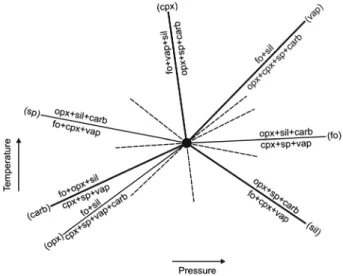
reactions of interest are vapor absent (Vap), silicate liquid absent (Sil), carbonatitic liquid absent (Carb), and cpx absent (Cpx) (with potential significance for harzburgite melting reactions). Schreinemakers’ construct of this PT invariance is shown in Figure 7. The carbonatitic liquid-absent curve (Carb) in Figure 7 is drawn with a positive slope as determined from the experiments reported here. Therefore, we have provided experimental confirmation on the form of the solidus in this part of the model, vapor-bearing peridotite phase diagram as originally drawn in Dalton and Presnall [1998]. The negative slope of the silicate liquid-absent curve (Sil) in Figure 7 is constrained by a run (“X” in Figure 6; taken from Ghosh et al. [2008] and Novella and Keshav [2010]) and the original form of the dolomite-absent (Dmt) PT-univariant reaction, forsterite + cpx + garnet + vapor = opx + liquid, emanating from the 2.6 GPa PT-invariant point in Dalton and Presnall [1998] (we note that the composition of the liquid in calculating the dolomite-absent (Dmt) reaction is not specified in Dalton and Presnall); thus, given the inferred PT-invariant solidus reactions at 2.6 GPa in Dalton and Presnall [1998] and their experimental con firma-tion [Ghosh et al., 2008; Novella and Keshav, 2010; this study], the silicate liquid-absent curve (Sil) in Figure 7 corresponds to the ledge and is required to have a negative slope. Further, the inferred dolomite-absent (Dmt) reaction of Dalton and Presnall [1998] at 2.6 GPa is of the form Figure 6. Shown as a continuous solid curve, this
pressure-temperature projection displays the experimentally deter-mined solidus of vapor-bearing, model peridotite (pdt) in the system CMAS-CO2over 1.1–2 GPa (this study). Subsolidus
and supersolidus experimental runs are shown by blank and grey-filled circles, respectively; dark, solid circles at 1.1, 1.4, and 1.9 GPa are bounds on the solidus and are placed as such to be in accordance with the subsolidus and supersolidus runs at these pressures. Isobaric invariance, achieved only at 1.7 GPa, is shown, next to a solid circle, by “Z.” Pressure-temperature invariance, at 2 GPa, is shown by an arrow next to“I.” Point X at 2.1 GPa is taken from Ghosh et al. [2008] and Novella and Keshav [2010]. Also shown are three other curves/lines: The dashed curve with a negative PT bend approximately over 1.9–2 GPa is the estimated solidus from Dalton and Presnall [1998], the solid line over 3–3.5 GPa is the experimentally determined solidus of carbonate-bearing, model peridotite (pdt) from Dalton and Presnall [1998], and the solid line over 1.1–2 GPa is the experimentally determined melting curve of dry, model peridotite in the system CMAS [Presnall et al., 1979; Liu and Presnall, 2000].
forsterite + cpx + spinel + vapor = opx + carbonatitic liquid in the experiments at 2.1 GPa [Ghosh et al., 2008; Novella and Keshav, 2010], shown as“X” in Figure 6; in the system CMAS-CO2, the liquid, in equilibrium with forsterite + opx +
cpx + garnet + crystalline carbonate, at 3 GPa, is carbonatitic in composition [Dalton and Presnall, 1998]. Accordingly, combination of Dalton and Presnall [1998], Ghosh et al. [2008], and Novella and Keshav [2010] would indicate not only that the liquid in the garnet-bearing dolomite-absent (Dmt) PT-univariant reaction, forsterite + cpx + garnet + va-por = opx + liquid, coming from the 2.6 GPa PT-invariant point in Dalton and Presnall [1998] is carbonatitic in compo-sition but also that the liquid, in equilibrium with the relevant phase assemblage, is carbonatitic between 2 and 3 GPa. Hence, along the curve (Sil) in Figure 7, silicate liquid and crystalline carbonate are absent, and vapor is present along with carbonatitic liquid. To recapture, along the ledge drawn in Dalton and Presnall [1998] (Figure 1), liquid is carbonatitic in composition. Given the data presented here (the invariant point at 2 GPa), the form of isopleths in Gudfinnsson and Presnall [2005], and the observation that Gudfinnsson and Presnall [2005] do not find evidence of liquid immiscibility in their work at 3.2 GPa (in agreement with the work of Moore and Wood [1998] at 3 GPa), it is required by Schreinemakers’ rules that the vapor-absent curve (Vap) in Figure 7 has a positive slope.
[27] Now because the melting reaction at 1.9 GPa is opx +
cpx + spinel + vapor = forsterite + silicate liquid and the reac-tion along the carbonatitic liquid-absent curve (Carb) in Figure 7 at the 2 GPa invariance is cpx + spinel + vapor = forsterite + opx + silicate liquid, it follows that between 1.9 and 2 GPa, the reaction would be cpx + spinel + vapor =
forsterite + silicate liquid, meaning that opx is on neither side of the reaction. Similarly, the melting reaction at 2.1 GPa is forsterite + cpx + spinel + vapor = opx + carbonatitic liquid, while the reaction along the silicate liquid-absent curve (Sil) in Figure 7 is forsterite + cpx + vapor = opx + spinel + carbonatitic liquid, indicating that between 2 and 2.1 GPa, the reaction would be forsterite + cpx + vapor = opx + carbonatitic liquid, with spinel being on neither side of the reaction.
[28] Given the position of the PT-invariant point I in
Figure 6, though it might be tempting to view it as a temper-ature maximum, the tempertemper-ature uncertainty in the experi-ments prevents us from drawing too firm a conclusion. Hence, the solidus can just as well be drawn smoothly be-tween 1.9 and 2.1 GPa, resembling the ones drawn in Dalton and Presnall [1998] and Gudfinnsson and Presnall [2005]. However, from our experiments, we suggest that the PT invariance at 2 GPa signifies the termination of the divariant surface over which carbonatitic liquids in equilib-rium with forsterite-opx-cpx-garnet are generated at 3.2 GPa [Gudfinnsson and Presnall, 2005]. We arrive at this conclusion from the following: (1) An experimental run 5°C higher (1425°C; Table 1) than the PT invariance at 2 GPa (1420°C; Table 1) has lost opx and spinel and is hence a five-phase assemblage (inclusive of two melts), and (2) the vapor-absent curve (Vap) has a positive slope, and the curve (Vap) not only must extend some distance onto the PT-divariant surface between the CMAS and CMAS-CO2solidi
from 2 to 3.2 GPa but also must delineate a geometrical boundary between carbonatitic and silicate liquids in equilib-rium with their respective crystalline phase assemblage. At 3.2 GPa, Gudfinnsson and Presnall [2005] do not find evi-dence of two melts in individual runs, lending assurance to our conclusion, and indicate that the vapor-absent curve (Vap) in Figure 7 containing two melts ends at pressures less than 3.2 GPa. Consequently, between 2 and 3.2 GPa, along the vapor-absent curve (Vap) in Figure 7, the composition of the two liquids, carbonatitic and silicate, would have to converge (inclusive of their CO2concentrations), such that
this (Vap) reaction terminates at an endpoint, where the reac-tion carbonatitic liquid = silicate liquid would occur.
[29] On the basis of the melting curve shown in Figure 6,
it would seem that carbonatitic and silicate liquids are pro-duced from direct reaction of vapor and silicates at 2 GPa. Therefore, liquids along the melting curve of model, vapor-bearing peridotite in the system CMAS-CO2, when
changing their composition from being silicate (1.9 GPa) to carbonatitic (2.1 GPa), undergo a step involving immisci-bility at 2 GPa. On the basis of the experiments reported here, and the ensuing interpretations, it just so happens that this liquid immiscibility also involves invariance. This in-variance is most likely the cause behind the changing liquid composition from 1.9 to 2.1 GPa.
[30] Therefore, along the solidus of model, carbonated
peridotite, it is neither the appearance of crystalline carbon-ate at about 3 GPa nor the increasing solubility of CO2in
liquids that causes the occurrence of the “ledge.” Rather, from the preceding arguments in our study, it is the PT invariance involving liquid immiscibility at 2 GPa which is most likely the reason for the appearance of the famed “ledge” at the solidus of carbonated peridotite composition space in the system CMAS-CO2.
Figure 7. Schreinemakers’ bundle for the relative positions of the stable PT-univariant curves that emanate from the experimentally determined PT invariance at 2 GPa, shown as “I” in Figure 6. Each phase-absent reaction is shown in parentheses. The metastable extensions of all the stable PT-univariant curves are shown in dashed. Four stable curves of significance, labeled carbonatitic liquid absent (Carb), silicate liquid absent (Sil), vapor absent (Vap), and clinopyroxene absent (Cpx), are shown in bold. Further details on this con-struct are under section 5. The rest of the abbreviations are as follows: fo—forsterite; opx—orthopyroxene; and sp—spinel.
6. Natural Carbonatitic and Carbonated Silicate Liquids and Experimental Work
[31] Many of the intrusive and extrusive carbonatitic
com-plexes in natural settings are quite frequently associated with quenched silicate melts [see Bailey et al., 2005, 2006]. The majority of carbonatites in such settings are more calcic in composition [Woolley and Kempe, 1989; Brooker and Kjarsgaard, 2011, and references therein] than those pro-duced in the experiments here; the silicate melts associated with these natural calciocarbonatites range approximately from being melilititic to nephelinitic in composition [Bailey et al., 2005, 2006, and references therein]. The experimental data presented here do not contain alkalies, iron oxide, or wa-ter, components that can have a significant influence on the melting phase relations [see Thibault et al., 1992; Sweeney, 1994; Moore, 2012]. Therefore, on this basis, a direct compar-ison of our data to experimental studies performed neither in slightly more chemically complex compositions nor with the natural occurrences is realistic. However, Bailey [1989] described carbonatitic pyroclastic deposits from the Rufunsa Valley in Zambia that contain melt droplets of iron-free dolo-mite (molar Ca# = 50–52; Ca# = Ca/Ca + Mg molar ×100), a
composition that is similar to the carbonatitic liquid seen in the experiments here. However, unlike at other localities (for example, Spain [Bailey et al., 2005] and France [Bailey et al., 2006]), associated silicate magmas at Rufunsa are absent [Bailey, 1989]. With the caveat that the genesis of carbonatitic and associated silicate liquids in nature and in more complex systems is likely to be more involved than that investigated here, it is possible that carbonatitic melts in Rufunsa could be due to liquid immiscibility, similar to that interpreted in the experiments reported here. Understandably, using Rufunsa [Bailey, 1989] as an example does not constitute a “global application” of the experimental results presented here, but such a wider use relies on thefirst-order task of clari-fying melting phase relations (built and researched on previous studies [Brooker and Kjarsgaard, 2011, and references therein]) in chemically simple systems. Yet it is also quite pos-sible that because carbonatitic liquid is produced at high temper-atures (point I in Figure 6), given suitable adiabats, such liquids, in general, might erupt through liquid immiscibility, as near-primary magmas on the Earth’s surface. And, insofar as adding more components to the system CMAS-CO2and systematically
understanding their individual influences on the melting phase relations are concerned, some holes in this direction are starting to get filled in (for example, CMAS-Na2O-CO2 at 3 GPa
[Moore, 2012]). In this system, evidence for the presence of two liquids (immiscible) has not been found at least at 3 GPa [Moore, 2012]. Therefore, future efforts could be directed at attempting to investigate the melting phase relations of model, carbonated peridotite in the system CMAS-Na2O-CO2(plus
systematic influence of other components; for instance, CMAS-K2O-CO2) over the pressure range of 1–2.8 GPa
(or beyond 3 GPa), and the expression (if there is) of such CO2-assisted melting in the mantle, on the surface of the Earth.
7. Conclusions
[32] Using a standard piston-cylinder apparatus, melting
phase relations of CO2-vapor-saturated, model peridotite in
the system CMAS-CO2 over 1.1–2 GPa were examined.
The melting curve has a positive slope in pressure-tempera-ture space, and silicate liquids (with about 2–8 wt % CO2)
are produced over the pressure range of 1.1–2 GPa in equi-librium with vapor and crystalline phase assemblage. Carbonatitic and silicate liquids, interpreted as being products of liquid immiscibility, are in equilibrium with vapor and crys-talline phase assemblage at 2 GPa. Therefore, if the melting phase relations are correctly interpreted, it is the invariance at 2 GPa which rationalizes the dramatic shift in liquid composi-tion from being silicate liquid at 1.9 GPa to carbonatitic liquid at 2.1 GPa, with a step involving liquid immiscibility at 2 GPa. On the basis of our study, we conclude that it is highly likely that the“ledge” in the carbonated peridotite composition space appears because of the very existence of PT invariance involv-ing liquid immiscibility at 2 GPa in the system CMAS-CO2.
[33] Acknowledgments. We thank Hans Keppler, Bjørn Mysen, Dean Presnall, and Bernie Wood for the comments, remarks, suggestions, and dis-cussions on various occasions related to the work presented in this manu-script. Richard Brooker, Robert Luth, two referees who wished to remain anonymous, and Journal Editor Michael Walter officially reviewed this man-uscript and are thanked for their comments on this manman-uscript at various stages. Richard Brooker, Robert Luth, and Editor Michael Walter noticed and brought to attention some fundamental oversights on our part, recti fica-tion of which significantly modified, and it is our hope, improved, the treat-ment in this manuscript. We thank our technical and administrative colleagues in Germany and France for their assistance. Bayerisches Geoinstitut, Germany, and partial defraying from the CIG Marie Curie EU grant (303301) to thefirst author supported this present research.
References
Bailey, D. K. (1989), Carbonate melt from the mantle in the volcanoes of south-east Zambia, Nature, 388, 415–418.
Bailey, K., M. Garson, S. Kearns, and A. P. Velasco (2005), Carbonate vol-canism in Calatrava, central Spain: A report on the initial findings, Mineral. Mag., 69, 901–915.
Bailey, K., S. Kearns, J. Mergoil, J. Daniel Mergoil, and B. Paterson (2006), Extensive dolomitic volcanism through the Limagne Basin, central France: A new form of carbonatite activity, Mineral. Mag., 70, 231–236. Brenan, J., and E. B. Watson (1988), Fluids in the lithosphere, 2. Experimental constraints on CO2transport in dunite and quartzite at ele-vated P-T conditions with implications for mantle and crustal carbonation processes, Earth Planet. Sci. Lett., 91, 141–158.
Brooker, R. A., and B. A. Kjarsgaard (2011), Silicate-carbonate liquid im-miscibility and phase relations in the system SiO2-Na2O-Al2O3 -CaO-CO2at 0.1–2.5 GPa with applications to carbonatite genesis, J. Petrol., 52, 1281–1305.
Buob, A., R. W. Luth, M. W. Schmidt, and P. Ulmer (2006), Experiments on CaCO3-MgCO3 solid solutions at high pressure and temperature, Am. Mineral., 91, 435–440.
Dalton, J. A., and D. C. Presnall (1998), Carbonatitic melts along the solidus of model lherzolite in the system CaO-MgO-Al2O3-SiO2-CO2, Contrib. Mineral. Petrol., 131, 123–135.
Eggler, D. H. (1973), Effect of CO2on the melting of peridotite, Carnegie Inst. Wash. Yearb., 73, 215–224.
Eggler, D. H. (1974), Peridotite-carbonate relations in the system CaO-MgO-SiO2-CO2, Carnegie Inst. Wash. Yearb., 74, 468–474.
Eggler, D. H. (1975), Composition of the partial melt of carbonated perido-tite in the system CaO-MgO-SiO2-CO2, Carnegie Inst. Wash. Yearb., 75, 623–626.
Eggler, D. H. (1976), Does CO2cause partial melting in the low-velocity layer of the mantle?, Geology, 4, 69–72.
Eggler, D. H. (1978), The effect of CO2upon partial melting of peridotite in the system Na2O-CaO-Al2O3-MgO-SiO2-CO2, with an analysis of melting in a peridotite-H2O-CO2system, Am. J. Sci., 278, 305–343.
Eggler, D. H. (1987a), Discussion of recent papers on carbonated peridotite, bearing on metasomatism and magmatism: An alternative, Earth Planet. Sci. Lett., 82, 398–400.
Eggler, D. H. (1987b), Discussion of recent papers on carbonated peridotite, bearing on metasomatism and magmatism: Final comment, Earth Planet. Sci. Lett., 82, 403.
Eggler, D. H., J. R. Holloway, and B. O. Mysen (1976), High CO2 solubil-ities in mantle magmas: Comment, Geology, 4, 198–199.
Gaetani, G. A., and T. L. Grove (1998), The influence of water on melting of mantle peridotite, Contrib. Mineral. Petrol., 131, 323–346.
Ghosh, S., S. Keshav, G. H. Gudfinnsson, and D. C. Presnall (2008), Detailed structure of the carbonated peridotite solidus ledge in the system CaO-MgO-Al2O3-SiO2-CO2, Transactions of the American Geophysical Union Fall meeting 89(53), MR43A-1798.
Gudfinnsson, G. H., and D. C. Presnall (1996), Melting relations of model lherzolite in the system CaO-MgO-Al2O3-SiO2 at 2.4–3.4 GPa and the generation of komatiites, J. Geophys. Res., 101, 27,701–27,709. Gudfinnsson, G. H., and D. C. Presnall (2005), Continuous gradations
among primary carbonatitic, kimberlitic, melilitic, basaltic, picritic, and komatiitic melts in equilibrium with garnet lherzolite at 3–8 GPa, J. Petrol., 46, 1645–1659.
Hammouda, T. (2003), High-pressure melting of carbonated eclogite and ex-perimental constraints on carbon cycling and storage in the mantle, Earth Planet. Sci. Lett., 214, 357–368.
Hirose, K., and T. Kawamoto (1995), Hydrous partial melting of lherzolite at 1 GPa: The effect of H2O on the genesis of basaltic magmas, Earth Planet. Sci. Lett., 133, 463–473.
Irving, A. J., and P. J. Wyllie (1975), Subsolidus and melting relationships for calcite, magnesite, and the join CaCO3-MgCO3to 36 kb, Geochim. Cosmochim. Acta, 39, 35–53.
Kushiro, I. (1969), The system diopside-forsterite-silica with and without water at high pressures, Am. J. Sci., 267A, 269–294.
Liu, T.-C., and D. C. Presnall (2000), Liquidus phase relations in the system CaO-MgO-Al2O3-SiO2at 2.0 GPa: Applications to basalt fractionation, eclogites, and igneous sapphirine, J. Petrol., 41, 3–20.
Liu, X., H. S. C. O’Neill, and A. J. Berry (2006), The effects of small amounts of H2O, CO2, and Na2O on the partial melting of spinel lherzolite in the system CaO-MgO-Al2O3-SiO2± H2O ± CO2± Na2O at 1.1 GPa, J. Petrol., 47, 409–434.
Luth, R. W. (1999), Carbon and carbonates in the mantle, in Mantle Petrology: Field Observations and High Pressure Experimentation, A Tribute to F.R. (Joe) Boyd, Geochemical Society Special Publication, 6, 297–316.
Luth, R. W. (2006), Experimental study of the CaMgSi2O6-CO2system at 3–8 GPa, Contrib. Mineral. Petrol., 151, 141–157.
Milholland, C. S., and D. C. Presnall (1998), Liquidus phase relations in the system CaO-MgO-Al2O3-SiO2at 3.0 GPa: The aluminous pyroxene ther-mal divide and high-pressure fractionation of picritic and komatiitic magmas, J. Petrol., 39, 3–27.
Moore, K. R. (2012), Experimental study in the Na2O-CaO-MgO-Al2O3 -SiO2-CO2system at 3 GPa: The effect of sodium on mantle melting to
carbonate-rich liquids and implications for the petrogenesis of silicocarbonatites, Mineral. Mag., 76, 285–309.
Moore, K. R., and B. J. Wood (1998), The transition from carbonate to sili-cate melts in the system CaO-MgO-SiO2-CO2, J. Petrol., 39, 1943–1951. Mysen, B. O., D. H. Eggler, M. G. Seitz, and J. R. Holloway (1976), Carbon dioxide in silicate melts and crystals. Part 1. Solubility measurements, Am. J. Sci., 276, 455–479.
Novella, D., and S. Keshav (2010), Silicate melt-carbonatite liquid immisci-bility reconsidered in the system CaO-MgO-Al2O3-SiO2-CO2at 2–3 GPa, Experimental Mineralogy, Petrology, Geochemistry (EMPG), Toulouse, France.
Presnall, D. C. (1986), An algebraic method for determining equilibrium crystallization and fusion paths in multicomponent systems, Am. Mineral., 71, 1061–1070.
Presnall, D. C., J. R. Dixon, T. H. O’Donnell, and S. A. Dixon (1979), Generation of mid-ocean ridge tholeiites, J. Petrol., 20, 3–35.
Sweeney, R. J. (1994), Carbonatite melt composition in the Earth’s mantle, Earth Planet. Sci. Lett., 128, 259–270.
Thibault, Y., A. D. Edgar, and F. E. Lloyd (1992), Experimental investiga-tion of melts from a carbonated phlogopite lherzolite: Implicainvestiga-tions for metasomatism in the continental lithospheric mantle, Am. Mineral., 77, 784–794.
Watson, E. B., and J. Brenan (1987), Fluids in the lithosphere, 1. Experimentally-determined wetting characteristics of CO2-H2O fluids and their implications forfluid transport, host-rock physical properties, andfluid inclusion formation, Earth Planet. Sci. Lett., 85, 497–515. White, B. S., and P. J. Wyllie (1992), Solidus reactions in synthetic
lherzolite-H2O-CO2from 20–30 kbar, with applications to melting and metasomatism, J. Volcanol. Geotherm. Res., 50, 117–130.
Woolley, A. R., and D. R. C. Kempe (1989), Carbonatites: Nomenclature, average chemical compositions, and element distribution, in Carbonatites: Genesis and Evolution, edited by Bell, K., pp. 1–14, Unwin, London. Wyllie, P. J. (1987a), Discussion of recent papers on carbonated peridotite, bearing on mantle metasomatism and magmatism, Earth Planet. Sci. Lett., 82, 391–397.
Wyllie, P. J. (1987b), Discussion of recent papers on carbonated peridotite, bearing on mantle metasomatism and magmatism: Response, Earth Planet. Sci. Lett., 82, 401–402.
Wyllie, P. J., and W. L. Huang (1976a), Carbonation and melting reactions in the system CaO-MgO-SiO2-CO2at mantle pressures with geophysical and petrological applications, Contrib. Mineral. Petrol., 54, 79–107. Wyllie, P. J., and W. L. Huang (1976b), High CO2solubilities in mantle