HAL Id: hal-02413867
https://hal.inria.fr/hal-02413867
Submitted on 16 Dec 2019
HAL is a multi-disciplinary open access
archive for the deposit and dissemination of
sci-entific research documents, whether they are
pub-lished or not. The documents may come from
teaching and research institutions in France or
abroad, or from public or private research centers.
L’archive ouverte pluridisciplinaire HAL, est
destinée au dépôt et à la diffusion de documents
scientifiques de niveau recherche, publiés ou non,
émanant des établissements d’enseignement et de
recherche français ou étrangers, des laboratoires
publics ou privés.
Early validation of satellite COTS-on-board computing
systems
Philippe Cuenot, Paul Bouche, Robert de Simone, Julien Deantoni, Amin
Oueslati
To cite this version:
Philippe Cuenot, Paul Bouche, Robert de Simone, Julien Deantoni, Amin Oueslati. Early validation
of satellite COTS-on-board computing systems. ERTS 2020 - 10th European Congress on Embedded
Real-Time Software and Systems, Jan 2020, Toulouse, France. �hal-02413867�
Early validation of satellite COTS-on-board computing systems
P. Cuenot1
4, P. Bouche1, R. de Simone3, J. Deantoni2, A. Ouestali1
1: IRT Saint-Exupéry, System Engineering department, Toulouse, France 2: Université Cote d’Azur, I3S/INRIA Kairos, Sophia Antipolis, France
3: INRIA Kairos, Sophia Antipolis, France
Abstract: The competitive market of nano and micro
satellites opens perspectives for use of COTS (Com-mercial Off-The-Shelf) electronic components. Cur-rent modular electronics design for embedded On-Board Computing systems (OBC) is being challenged by the integration of flexible Systems on Chip (SoC). The deployment of generic avionics and user/payload functionalities on these components is becoming in-creasingly complex, while Quality of Service must re-main compliant with demanding requirements. It is therefore most important to estimate/evaluate those properties as early as possible, regarding a given ap-plication’s deployment on a given COTS-based archi-tecture. Model Based System Engineering (MBSE), while a leading practice in architecture description, may still require further study on its use for early eval-uation, especially regarding analysis of emerging be-haviors and qualitative model-based mapping of ap-plicative functions onto architectural platform.
In this paper, we present methods to enhance MBSE design, helping the designer in evaluating candidate mappings and design choices by providing concrete quality measures. We focus on two aspects that were identified as critical in the ATIPPIC IRT project: first, the cost and conflicts in data communications in on-board and peripheral interconnects, which has a bot-tleneck impact on mapping choices; second, the availability of functions in case of resource failures (from solar radiations), to validate fault-mitigation techniques and estimate the (un)availability of the OBC system.
We illustrate the approach on a simplified satellite model, abstracted from a design conceived in the ATIPPIC IRT project.
Keywords: MBSE, Virtual engineering and
Simula-tion, FPGA, Dependability.
1. Introduction and Motivation
The space industry is opening to the trends of micro- and nano-satellites, meant to cover the market of sat-ellite-based services. Potential embedded applica-tions, from broadband internet to specific earth obser-vations, will require low-cost, flexible and reliable electronics architecture to keep competiveness. Mod-ular and integrated electronic architecture, a para-digm already established in other industries, is now crawling into aerospace industry, in the hope to build affordable products using Commercial Off-The-Shelf
4 Seconded from Continental Automotive France, Toulouse France
electronic components (COTS) for greater integra-tion. In particular, modern Systems on Chip (SoC) in-volves more diverse computing power (CPU, FPGA…), incurring flexibility of application deploy-ment, and possible On-Board Computing system (OBC) reconfiguration.
Of course, this flexibility comes at the cost of numer-ous design space alternatives. To fully exploit the benefit of SoC performance, a key issue is to devise efficient component mapping (in physical allocation and temporal scheduling).This includes the impact of OBC and peripheral SoC communications intercon-nects: communication conflicts (bottleneck interfer-ences) may drastically downgrade time responsive-ness of applications. The ambition is to estimate
con-flicts (interferences) and congestions of SoC
inter-connects and to estimate bottleneck latency effects on function execution. Another important challenge in aerospace domain is the need for
dependabil-ity/availability. This is especially important regarding
sensitivity of standard SoCs to cosmic radiations since they are not physically hardened. Therefore fault detection, isolation and recovery (during FDIR) must be introduced to optimize operational (safe) availability, itself a dual requirement (fixing failures must not impair too long operationally). It becomes very important to evaluate impact of safety mecha-nisms on an architecture including effects on bus con-gestion. Here we target the estimation of operational availability considering effects of fault mitigation in-side and around the SoC.
One of our main objective was to use the same archi-tecturo-functional modeling platform as a common basis to build extensions on Performance for conges-tion analysis and Safety for availability analysis. Fur-thermore, we aim to exploit this modular structure to be able to localize precisely the distinct modeling re-quirements facing distinct domain expertise, which could become rather independent inputs that distinct experts concentrate on without overview on global im-pact. Modeling consistency between viewpoints is a big challenge to foster potential dialog between local experts under supervision of the general system de-sign architect.
Our paper is structured as follows. Section 2 intro-duces related methods on Model Based System En-gineering and Analysis used for availability and per-formance early evaluation. Section 3 documents the
motivational setup defined by COTS-based OBC de-sign within the IRT ATIPPIC project. Section 4 intro-duces the proposed method for consistent analyses of congestion and availability. Section 5 provides in-sight results respectively for congestion evaluation and availability analysis. Finally, the conclusion in chapter 6 reports feedback on our approach and draws perspective for future work.
2. Related Work
Model Driven Engineering, introduced to assist de-sign in the early stage of development flows, is be-coming a common practice in some system engineer-ing disciplines [1]. System engineerengineer-ing later combined MDE with other domain-specific modelling paradigms to reach Model Based System Engineering (MBSE), and support analysis and description of both system architecture and functionality (and their mutual map-ping). The OMG standardized the SySML1 profile,
nowadays available in numerous commercial tool, and the Capella2 open initiative provides the
Arca-dia/Capella [2] modelling environment. AADL is a third example of such MBSE solutions. From ,a soft-ware point of view, they all provide basic means to describe tasks and functions of an application, as well as architectural block diagrams for execution plat-forms, and simple means to describe candidate map-ping allocations between them. They all also require modelling language extensions to provide the extra information and annotations required to cover do-main-specific analysis of different objective domains (performance, consumption, heat, memory print, safety, security, and so on). The language extension must be complemented by tool viewpoint driven ap-proach as recommended by ISO/IEC 42010 standard. The UML/SysML modeling language extension led to the OMG UML MARTE3 profile, which offers
speciali-zations for Non-Functional Values, for real time appli-cation descriptions, and including hardware compo-nent descriptions.
In this work we propose to extend Capella by provid-ing additional viewpoints associated with a formal be-havioral semantic to analyze Physical Architectures. The selection of Capella was made as it complies with practices of some ATIPPIC partners. Additionally the MARTE Hardware Resource Management (HRM) concepts was used as primary inspiration for lan-guage extensions.
Regarding interconnect congestions, other solutions could be considered, at least partly. For example, TTool\Diplodocus [3, 4], is a modelling tool based on UML/SysML developed by Telecom ParisTech. As in other so-called Platform-Based Design (PBD) hard-ware/software co-design tools, design space explora-tion may be conducted through model translaexplora-tion and
1 https://www.omg.org/spec/SysML 2 https://www.polarsys.org/capella/ 3 https://www.omg.org/omgmarte/
4 http://accellera.org/downloads/standards/systemc
then external simulation based on the SystemC4
hard-ware simulation language. Bus congestion analysis may be performed, but requires the existence of pre-defined SystemC blocks. The same construction ap-plies to the commercial-strength Platform Architect5
tool from Synopsys. PBD using SystemC generally demands hardware design skills rather than system’s one (at the level considered in this work). Finally, there exist network simulation frameworks such as NS-3 [5] and OMNET++ [6] specialized in network protocol accurate simulation. This kind of frameworks does not consider hardware platforms close to our do-main with regard to SoC decomposition.
On the availability assessment calculation side, a few commercial or in-house solution exists. Based on Model Based Safety Analysis (MBSA), they are capa-ble to assess safety but also availability of critical em-bedded system. The closer tool from our goals and partnerships are based on the Altarica language, as per see SiMFIANeo [7] (developed by APSYS and in-tegrated in Eclipse like Capella) or the open source initiative Altarica 3.0 [8] developed by IRT SystemX6.
Both allow a system description using the Altarica syntax, and then performing stochastic simulations to evaluate availability. In practice, the Altarica model-ling stays at a functional system level, fault propaga-tion occurs between funcpropaga-tions and within hardware components. Actual practice availability analysis are performs on full system level, while our study focus on low level SoC including its local reconfiguration. Eval-uation with stochastic simulation may require long computing time often not compatible with interactive design). Moreover, tool development efforts for an in-tegration in a single evaluation environment have to be considered. We concentrated our study on an in-tegrated solution that keeps a unique Capella model-ling environment. That way, we directly handle a unique system model using additional and existing re-lationships and properties.
3. Motivational Use-case Set-up
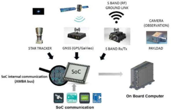
The satellite electronics use-case architecture con-sists of 3 main layers: a) the COTS SoC is a Xilinx Zynq7000 processor, with a dual-core CPU and FPGA computing power; b) two such SoCs are inte-grated in a Hyperion OBC Board, together with rad-hardened controllers and peripherals; c) finally the global architecture provides satellite communication features and sensor/actuator systems (cameras, an-tennas, engines…). The flexibility in mapping compu-tations to CPU or FPGA poses constraints on the in-ternal communications and data transfers. The two-SoCs redundancy allows various schemes of fault mitigation (which may differ on FPGAs and on CPUs). Reducing interconnect congestion, characterizing the satellite availability under given mitigation schemes
5
https://www.synopsys.com/verification/virtual-prototyping/plat-form-architect.html
and analyzing influence on each others were the main design requirements that prompted this study.
On the applicative side, standard avionic functions manage the satellite: Star Tracker determines the at-titude, GNSS acquires the position, On-Board Time maintains timing accuracy, AOCS controls the atti-tude and trajectory, and Telemetry/Telecommand manages RF communications with the ground. In ad-dition, a Payload application realizes custom user missions (generally, earth observation with image ac-quisition, compression, storage and ground down-loading). These functions are each mapped onto all three architectural layers, with computations and memory storage on the SoC, and communications in-side and across levels using relevant interconnects (CAN to interface sensors or payload equipment, SpaceWire to interface sensors and actuators such
as payload signal acquisition and propulsion/energy control …).
Regarding fault tolerance, the OBC architecture is based on a cold redundant architecture, each channel being composed of a set of two hierarchical watch-dogs. The Zynq is supervised by an external Supervi-sor Unit (SRU), the SRU by a hardware watchdog. The Zynq embeds fault mitigation components, either by triplication of critical hardware IP features in the Programmable Logic (PL), or by embedding a dedi-cated IP for detection and/or mitigation of FPGA con-tent such as configuration integrity verification (SEM IP) or supervisor, or via additional software function segregated on each core in the Programmable Soft-ware area (PS). Full safety and mitigation concepts are not further detailed in this article only an excerpt is considered.
The Zynq architecture set-up for later assessment co-vers the need of a spectrometry payload. It requires a large data exchange from spectrometry camera and intensive computation for Fast Fourier Transforms (FFT). The mission control unit controls image acqui-sition via a SpaceWire link. The acquiacqui-sition IP stores them in memory. The FFT function operates a calibra-tion and FFT computacalibra-tions on the stored images, which are then compressed and stored them in the NAND flash external memory via an I2C link. Mission control also operates image data transfer from the flash memory to the Radio Frequency (RF) communi-cation unit via the TMI LVDS link, this is to enable ground transfer. The mission’s challenge is to
im-Figure 2: Zynq architecture overview in Capella Figure 1: Satellite architecture/OBC overview
prove earth observation performance with the intro-duction of a second channel of acquisition, computa-tion, compression and transmission with regards to the second payload. The increase in data traffic may affect memory and interconnect components with concurrent access from PL and PS. A bus perfor-mance analysis must be completed.
The satellite cruises on a Low Earth Orbit (LEO), it is sensitive to radiations. Indeed, bit flips may occur, caused by Single Event Upsets (SEU) in hardware re-sources. SEUs can either lead to Single Bit Upsets (SBU) or a Multiple Bit Upsets (MBU). The challenge is then to demonstrate a sufficiently low value of una-vailability with this given architecture. For simplicity purposes, the satellite control is abstracted and imple-mented with a compute (COM) / monitoring (MON) software architecture. Additionally, a SEM IP is intro-duced for detection of PL configuration integrity stored in RAM (CRAM) with a supervisor function for mission mitigation strategy management. The effi-ciency of this detection/mitigation set-up in the Zynq architecture must be analyzed to identify its impact on the overall satellite mission’s availability and perfor-mance.
The corresponding Zynq architecture used for the demonstration and assessment of the proposed methods is depicted in Figure 2. The various model-ing concerns regardmodel-ing availability analysis when mapped on our use case are displayed on Figure 2. The functional chain considered runs through all func-tional blocks (in green), while extra "safety-funcfunc-tional" blocks are added (in light blue). The main computa-tion splits in two branches (respectively blue and pur-ple arrows), with cascaded functions running either on CPUs (top) or FPGA (bottom). Additional safety fea-tures are located on top center (Supervisor and Com-parator, and also partly the secondary Satellite Con-trol MONitor), and on lower-left Mitigation block. Every functional block needs proper information on how "raw" radiation upsets locally lead to failure rates in Erroneous/No Data range (recalled with the sun-shaped icon top-right). Quantitative figures about fault detection and mitigation (duration, latency...) will an-notate the Supervisor and SEM IP safety functions.
4. MBSE methods for early analysis of SoC deployment
To keep models tractable, while rich enough to sup-port the evaluation of candidate deployments of appli-cations on the SoC with support for domain specific engineering analysis (and further impacts the whole architecture), we need: (i) to rely on an existing (famil-iar?) modelling framework, (ii) to precisely identify rel-evant properties to analyze, (iii) to identify (or de-velop) a tooled environment that may facilitate the analysis and hide most of its complexity to the de-signer.
7 https://polarsys.org/kitalpha/
For (i) and (iii) justifications we selected Capella Stu-dio, together with the Kitalpha7 eclipse plug-in,
allow-ing creation of domain-specific viewpoints. View-points may help to reconcile analysis and evaluation of non-functional requirements managed across dif-ferent disciplines and expertise, while keeping the overall system model consistent. We identified that the physical layer as the adequate modelling layer in Capella to introduce function-to-resource allocations. It corresponds to entities and viewpoints of the Phys-ical Architecture Blank diagram (PAB). At this level, we specialized data models with adequate properties and new viewpoints.
We consider two kinds of evaluation: (i) static analysis methods, assuming worst-case conditions and pro-ducing fast, coarse results; (ii) operational analysis. Relying on dynamic simulation scenario (that may be exhaustive) for more accurate (but computationally costly) results.
To build the correct emerging behavior in (ii), a be-havioral semantic must be defined at the appropriate level of abstraction. For this we use the Gemoc8
stu-dio, also an eclipse plugin (as Kitalpha), especially meant to define formal operational semantic for simu-lation. Gemoc provides an interpreter, a debugger and a compiler. Its operational analysis semantic complies with data model extensions, allowing prop-erty-based calculations (with Java code).
To complete system design analysis we applied the evaluation approaches on our two target fields: (i)
congestion analysis, mostly here by computing
in-terference and (over)load among the SoC buses, usu-ally built from hardware and software expertise, (ii)
availability analysis, establishing mission
unavaila-bility due to component sensitivity to radiation failures and mitigation mechanisms of the design, involving safety and reliability expertise. The proposed meth-ods are detailed in turn.
Congestion Analysis
The objective of congestion analysis is to be able to predict and bound memory traffic on SoC internal buses and interconnects by identifying their latencies and throughputs. This allows system designers to val-idate the application function allocation on hardware resources (PS or PL) by estimating the data transfer impact on micro-architectural buses for coverage of application function performances (communication flow compliance and timing latency).
The congestion analysis information was already pub-lished in [9]. Below we only summarize principle to understand the evaluation. We also document im-provements made to support more complex scenario during the operational method.
We identified which model elements truly influence the interconnect traffic (computations, communica-tions, memory storage). We annotated these
ments with properties providing dimensions and be-haviors of the bus transaction communication. An ex-ample is displayed in Figure 3 (with additional meth-ods/functions used by Gemoc for simulation).
The analytic method is a simple and fast method to compute bound values. So in memory transaction, we consider only static configuration, meaning 1) every transactions are atomic, 2) interconnect arbitration is not considered 3) every transactions crossing a bus port interface are concurrent.
For each component execution (task) of the system we computed a maxDelayTime corresponding to the maximum time during which a task can be blocked by other tasks using the same interconnect bus port in a period, the hyper period of the system. For each bus we computed maxInterference as the maximum time during which the bus can have data blocked on its in-terface computed in a hyper period, and load as oc-cupation of the bus computed in a hyper period. These blocking situations consider worst case condi-tions on interconnect port due to 2) and 3), so com-puted value are pessimistic and deserve as first idea for performance evaluation on bus congestion. Kital-pha is used to develop Capella view point including Java code for calculation of these estimations. The operational method allows to refine previous re-sults based on simulation scenario. We used the Gemoc studio [10] facilities to define an operational semantic for the execution of the Capella PAB dia-gram extended viewpoint. Initiators of memory trans-action are tasks (component execution) with behavior properties defined from data model of Figure 3. We consider a Read, Execute Write task execution para-digm with randomized time execution between its best and worst case value to implement execution variation. Read or Write memory transaction can be blocked by another on-going transaction, delaying task execution. In [9] we considered only atomic memory transactions, the base time for encoding Gemoc simulation step. We now allow to decompose large memory transactions in beats corresponding to burst transactions. Moreover, we extend the schedul-ing semantic with Least Recently Granted (LRG) and Priority based schemes to support advanced function-alities of interconnect and memory controller
compo-nents. This evolution covers the abstract representa-tion of QoS services of Zynq interconnect arbitrarepresenta-tion. Priority settings. It also allows to perform arbitration during Read/Write memory transactions on each burst frame, to respect priority setting in function com-munication scheduling when large transaction frames are managed.
The link between the Capella meta-model extension and Gemoc execution is built with function defined in Figure 3 implementing system behavior and with ad-ditional action required to compute bus load and inter-ference. This is a so-called Domain Specific Action (DSA) which is triggered by a Domain Specific Event (DSE). As several occurrences of objects may exe-cute in parallel, Gemoc generates a Model Specific Event (MSE) as an ordered set of event occurrences required to trigger each DSE event instances. Execu-tion order is defined by specifying invariants in CCSL (Clock Constraint Specification Language) and in MoCCML (Model of Concurrency Modeling Lan-guage) [11]. MoCCML semantic is implemented by an automata, where each transition is triggered by a time event [12]. The physical time is built according time event, with resolution matching the smallest encoded memory transaction.
According to Zynq QoS specifications, its implemen-tation requires two level of arbitration, first a priority based on master port and then a LRG based for mul-tiple request with same the QoS value. The QoS value is simply abstracted by the transaction decomposition in beats with a fixed burst size. First we added the required properties, respectively priority level and burst length, on the master port of interconnect com-ponents using Kitalpha in the viewpoint extension. Then for the priority based policy, arbitration con-straints were added in the DSE using OCL invariants at the meta-model level as a part of the semantic. By navigating in the model using OCL queries, we are able to compare the QoS signals of the concurrent communications and grant the bus access to the transaction with the highest priority. Applying this to a concrete model, when loading the model, Gemoc will generate a “prioritymodel” file in which priorities be-tween transactions are specified explicitly. The file will then be given as an input for the simulation engine. During the simulation, when two (or more) concurrent events corresponding to concurrent transactions ap-pears, the choice of the simulation engine will be de-pend on the priority file. For the LRG arbitration scheme, we used a different approach since it was not meant to be encoded in the semantics but rather in a dedicated simulation policy. In the LRG scheme, priorities are not specified explicitly in the model as their values change over time. Indeed the dynamicity of priorities makes it impossible to give a priority order between the different transactions. Therefore, instead of adding the arbitration to the model’s semantics, we extended the Gemoc concurrent engine with a simu-lation policy based on the LRG scheme. The algo-Figure 3: Congestion Domain model
rithm manages choices for multiple requests on arbi-tration points for different communications on the same bus coming from different paths allowed on the state space of the simulation. It selects the highest priority among the bus requests.
Gemoc is so integrated with Capella Studio to allow simulation of PAB extended viewpoint and display es-timation of bus interference and load.
Availability Analysis
In this work, we want to assess the unavailability of each functional chain composing the system and sum the obtained values to get the overall unavailability. The unavailability of a functional chain occurs when it is no longer capable of doing its intended purpose cor-rectly. This happens when one or several critical func-tions do not behave as intended anymore. In our work, failures are caused by SEUs in hardware com-ponent and are reflected through the data exchanged between functional components. These failure can be spread between functions since every data is con-sumed by a function to output new data and a failure in an input data can lead to a failure in the output data. Ultimately, we want to assess the duration taken by the system to detect and mitigate such failures. The focus of this analysis lies in evaluating the con-sequences in terms of functional failures of the afore-mentioned radiation upsets occurring in hardware. In-deed, we assume that each functional component re-lies on one or several hardware components to achieve its intended purpose. Therefore, the occur-rence of a SBU or MBU in a hardware component, may affect the functional behavior of any logical com-ponent relying on it. These failures are potentially propagated from a function to another within the sys-tem and ultimately lead to its unavailability. In order to assess this impact, we introduce three abstract data-oriented failure modes for functional components:
Erroneous Data In Range (EIR) is the result of either the alteration of required data, or in-structions leading to a modification of the out-put data while staying in their functional range.
Erroneous Data Out of Range (EOR) is the result of either the alteration of required data, or instructions leading to a modification of the output data lying outside of their functional Finally, No Data (ND) ) is the result of either
the alteration of required data, or instructions leading to the logical function to cease provid-ing data
The method described hereafter concerns the analyt-ical analysis. Therefore, some assumptions are re-quired. According to experts, the SEU probability’s or-der of magnitude and the usual failure mitigation du-ration, we assume that situations where a SEU occurs while a first one has not been detected/mitigated with are very unlikely and are not considered in this paper. Moreover, failures can be volatile, in the way that data are cyclically overwritten and thus any SEU modifying
such a data will only last temporarily. Conversely, some SEU will never disappear unless a corrective action is undertaken.
We consider the relation between upsets and func-tional failures as being purely probabilistic. For a given logical component L, S is the set of sensitive physical components relied upon by L, the probability of a given failure to happen in L is computed as per:
𝑝𝐿(𝑓𝑎𝑖𝑙𝑢𝑟𝑒) = ∑ ∑ 𝑝𝑖(𝑗) × 𝑝𝑖(𝑓𝑎𝑖𝑙𝑢𝑟𝑒 | 𝑗) 𝑗∈𝑢𝑝𝑠𝑒𝑡
𝑖∈𝑆
× 𝑢𝑠𝑎𝑔𝑒𝑅𝑎𝑡𝑒(𝐿, 𝑖)
where, 𝑢𝑝𝑠𝑒𝑡 = {𝑆𝐸𝑈, 𝑀𝐵𝑈} 𝑝𝑖(𝑗) is the probability of 𝑗 happening in 𝑖
𝑝𝑖(𝑓𝑎𝑖𝑙𝑢𝑟𝑒 | 𝑗) is the probability of 𝑓𝑎𝑖𝑙𝑢𝑟𝑒 to happen
in 𝑖 knowing 𝑗 𝑢𝑠𝑎𝑔𝑒𝑅𝑎𝑡𝑒(𝐿, 𝑖) is the usage rate of 𝑖 made by 𝐿 The usage rate of a hardware component by a logical component depends on the former’s nature. To tackle this we propose, as per the congestion analysis, three hardware resources specializations: communication resources (i.e. bus and I/O controllers), execution re-sources (i.e. CPUs) and storage rere-sources (i.e. data and instruction memories).
Moreover, failure states can spread across functional components within a functional chain and ultimately lead to its unavailability. Indeed, as mentioned before, some functions within a functional chain are critical to ensure proper functioning. To reflect it in our model, the designer must indicate at least one function deemed critical to assess the functional chain’s una-vailability. This is happens when due to failure propa-gation, at least one of these functions has any of its input in any failure mode. We introduce failure propa-gation truth tables, to reflect this propapropa-gation within functions and functional data exchanges. For a com-ponent with m input and n output, the truth table ex-presses the failure state of each of the n output de-pending on the possible combinations of the m input failure states. Regarding functional data exchanges, the goal is to express the impact of the lower level communication medium’s nature on failure propaga-tion. For instance, in case the data propagation uses a shared memory, when no data is output by the sending function, the receiving function will read the previously stored value which, in our model, is an Er-roneous Data In Range. Since this case is relatively specific to some means of communication, we pro-pose to apply the identity transformation unless a truth table is provided.
We need to express how these failures are detected and mitigated within the system. The European Co-operation for Space Standardization (ECSS) pub-lishes guidelines regarding radiation effects mitigation [13]. Although, this work utilizes only a subset of the mechanisms described in this document, we aim at providing the capability to model them all. Detection mechanisms either ensure SEU detection directly in
the hardware or their consequences as logical level failures. They are characterized by a list of monitored components, the type of event (a SEU or a failure) detectable, and the detection duration. When a detec-tion happens an event detecdetec-tion signal is sent to a mitigation component. The latter is responsible to trig-ger recovery actions. We suggest the following syntax to express recovery actions’ definition: “N occur-rences of detectionSignal implies componentList un-available for mitigationDuration.”
N indicates the number of successive detectionSignal
required before triggering the action, detectionSignal is the signal send by a detection mechanism,
compo-nentList indicates the components affected by the
re-covery action and the rere-covery action lasts
mitiga-tionDuration time. Physical components, logical
com-ponents and functional chains are the type of compo-nent which can be affected by a mitigation action. This mean these components are reinitialized to a nominal state. During the mitigation duration any logical com-ponent either directly mentioned or taking part of a listed functional chain or relying on a listed physical component outputs No Data. Therefore, the functional chain might be unavailable during the recovery action depending on the failure propagation.
A function’s unavailability contribution is computed using the dedicated algorithm for the analytical analy-sis, where time is only seen as a parametric value. Indeed, only temporal characteristics are used in this analysis.The main idea is for of each dependency’s upset happening to check whether a detection and a mitigation mechanism exist. If it does to assess, based on the impacted components, if it corrects the upset and whether the action generated unavailabil-ity. Then, the upset is converted into the various fail-ure mode for the function under scrutiny. The capabil-ity to detect and mitigate each failure state is as-sessed for each functional component from the tion under scrutiny and going downstream the func-tional chain. The mitigation duration taken is the max duration found. The summation of this computation for every functional chain provides the system’s una-vailability.
Relevant information for this analysis originates from several --quite different-- sources of engineering ex-pertise. In our approach we wish to localize the dis-tinct contributions and promote their modular design. We propose a viewpoint-oriented model where each of the contributors input the assessment’s required in-formation independently. Radiation specialists should provide sensitivity rates towards SBUs and MBUs; while hardware engineers provide the bandwidth (communication resources only) and size (storage re-source only); software engineers consider the de-pendencies of functional components towards hard-ware components along with their usage (throughput for a communication resource, usage percentage for an execution resource or memory size for a storage resource) and radiation upset to failure conversions;
safety engineers should provide the detection and mitigation mechanisms.
5. Assessment results Congestion assessment
The scenario for the use case assessment, presented in section 3, aims to demonstrate that the OBC archi-tecture is able to support the increase of data transfer in SoC internal buses due to the introduction a second spectrometry channel and to co-exist with detec-tion/mitigation safety functions. We concentrated our study on buses accessing the DDR memory
Control-ler because of the large size of added data transfer
(150 Mb every second). The memory controller (and DDR memory) is a shared resource between logical functions, for data transfer. Depending of function scheduling points (offset parameter value for execu-tion component), bus load and latency may be strongly affected as we will demonstrate in this exam-ple. Every memory transaction used to configure IPs in the PL area are ignored, since they correspond to a low volume of data (only some sporadic frames). Payload IPs are connected to a dedicated interface port of the DDR interconnect, different from the one of the satellite control IPs. The purpose is to ensure safety via segregation of memory transaction flows. Traffic on these bus interfaces is then ignored. So we analyze congestion and latency on CortexToDDR,
AXI_HP2 and AXI_HP23 bus of Figure 2 and impact
on delayed function execution.
The first evaluation consists in analyzing dual spec-trometric mission, build with respective logical blocks
Satellite Control COM (rate 10Hz, offset 100ms,
op-erating control with R/W of 300Kb of data), SW
pay-load driver (rate 1Hz, offset 0, transmitting SPW
con-trol with R/W of 1Kb of data), SPW Acquisition1&2 (rate 1Hz, offset1 0ms & offset2 200ms, acquiring data from SPW and writing in DDR 150Mb of data),
FFT1&2 (rate 1Hz, offset1 200 & offset2 300, reading
150Mb of data, performing FFT and compressing them to 3Mb and writing data in DDR), I2C
Stor-age1&2 (rate 1Hz, offset1 900ms & 1100ms, reading
3Mb of data from DDR and writing them in NAND flash). LVDS Downlink1&2 are not considered in this analysis as manipulated data are directly copied from the NAND flash to the RF communication component by point to point buffered data communication, and so are not sharing DDR component. The minimum data size configured in the tool is 1 Mb (actual tool con-straints) and memory transactions are managed in 4Kb burst size (maximum size of Zynq AXI specifica-tion). Memory controller is configured with LGR policy on master port as default configuration, so call fair configuration. In a second step, we configured high priority for memory transaction of safety related func-tion (Supervisor, Comparator and Satellite Control MON&COM) to mimic priority control on communica-tion scheduling. All bus are configured in 64bits width
and 1.2 Gb as maximum bandwidth. We assumed that memory controller is “enough” performant to guarantee full bus bandwidth on CTRLToMemory bus for access to DDR memory.
The analytic evaluation computes the bus load value and the maximum interference rate for each bus, as well as the maximum delay time and communication transfer time for each function involved in the analy-sis. The results are directly displayed in the Capella viewpoint (see Figure 4). Values provided are worst case values, since dynamic conditions such as func-tion scheduling offsets or communicafunc-tion transacfunc-tion priorities are not considered.
Figure 4: congestion analytics results display When introducing safety blocks, Satellite Control
MON (rate 10Hz, offset 100ms, operating control
monitoring with R/W of 300Kb of data), Comparator (rate 10Hz, offset 150ms, mitigating COM/MON re-dundancy with R/W of 300Kb of data) and Supervisor (rate 10Hz, offset 200ms, mitigating hardware failure with 20Kb of data) the bus load and inferences in-crease on CortexToDDR bus, while remaining con-stant on other AXI_HPx buses (see results in Table 1). Indeed, the safety components are only introduced on the PS side, connected to memory via the Cortex-ToDDR bus, and additional data transfers (6Mb) are limited compare to initial transactions (310Mb). We can first conclude that the proposed architecture is ca-pable of handling the data bandwidth with a dual spectrometry mission including satellite control integ-rity services. Function delays need to be bounded with more precise values (and especially safety ones).
CortexToDDR AXI_HP23 AXI_HP2 Dual spectrometry payload (Analytic)
MaxInterenceRate 25.6% 25.25% 25.25% Load 28.8% 25.5% 25.5%
Dual spectrometry payload with safety function (analytic) MaxInterenceRate 26.16% 25.25% 25.25% Load 33.8% 25.5% 25.5%
Dual spectrometry payload (Operational and Fair)
Table 1: Congestion analytics results
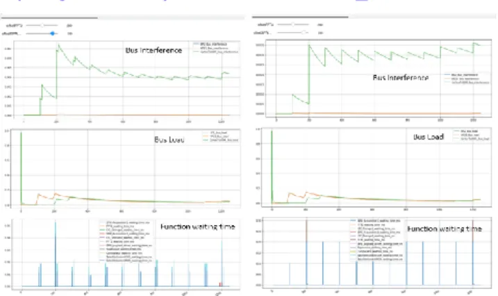
The operational analysis method brings more precise results as we can see on Figure 5, with results varia-tion over time. To minimize bus congesvaria-tion, we per-formed an exploration of scheduling offsets. This ex-ploration was performed thanks a DSL capable to de-fine simulation scenario (see [9] for DSL information). The explored configurations are performed by shifting
the offset of the main consumer in data transactions on the second payload, such as Acquisition2 and FFT2 functions. Offset varies respectively between [0-100] and [200-360] with an exploration step of 20 for each. Every simulation results are accessible at the following URL:
https://github.com/jdeantoni/ERTS2020_artifacts.
Figure 5: Congestion operational results The analysis was performed in fair transaction mode (LRG) left side of the Figure 5 (payload with safety) and with high priority setting for safety functions on the right side. We record 4% of interference on Cor-texToDDR (green curve) and maximum 10% of band-width after stabilization (green curve). Produced re-sults are clearly more precise than analytical methods and allow to interpret the waiting time for each func-tion. The impact of priority setting shows that bus in-terference is increased, since safety functions delay large frames, getting more impact on the overall inter-ference. We demonstrate that such operational anal-ysis allow to better analyses provisional bus conges-tions thanks to a scheduling proposed design on the system architecture.
Availability assessment
This section aims to demonstrate, using the analytical method defined in section 4, on the use case defined in section 3, how the introduction of detection and mit-igation mechanisms reduces the system’s unavaila-bility, in the use case under study the Zynq is the sys-tem. In this assessment, we only study sensitivity to-wards SBUs, for simplicity purposes. The following data are used regarding sensitive hardware compo-nents, the sensitivity is expressed in number of SBU happening per device per day: CPU Cores 3.52E-3 SBU/day, DDR 2.25E-2 SBU/day Memory, FPGA CRAM 4.57E-2 SBU/day and NAND Flash 3.06E-3 SBU/day. In terms of functional to hardware compo-nent dependency, the following is used: Satellite Con-trol COM depends on Core 2 (15%) and DDR Memory (996 kB), Satellite Control MON depends on Core 1 (15%) and DDR Memory (996 kB), SPW Payload Drive depends on Core 1 (5%) and DDR Memory (100 kB), SPW Acquisition 1 and 2 depends on CRAM (20 Kb) and DDR Memory (80 kB), FFT1 depends on Core 1 (20%) and DDR Memory (150 Mb), FFT2 de-pends on Core 2 (20%) and DDR Memory (150 Mb), I2C Storage 1 and 2 depends on CRAM (10 kB) and
DDR Memory (3 Mb), Payload Control depends on Core 1 (10%) and DDR Memory (50 KB), LVDS Downlink 1 and 2 depends on CRAM (10 kB), DDR Memory (80 KB) and NAND (3Mb), the Comparator depends on Core 1 (5%). The upset to failure rates are taken into account but are not shown in this due to a lack of space. Just as an example, for Satellite Control COM and MON we have SBU in Core leading to 80% of Instruction Errors with 100% of ND, to 20% Data Error which volatile (because happening in reg-isters which are overwritten frequently) with 50% of EIR, 50% of EOR and SBU in DDR leading to 100% Data Errors with 80% of EIR, 20% of EOR.
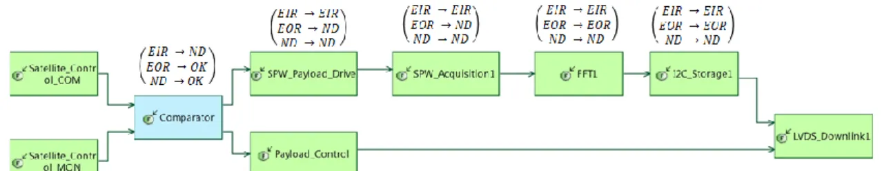
In terms of failure propagations, every data exchange between the PS and PL uses a shared memory. Therefore data exchanges between SPW Payload Drive and SPW Acquisition (1 or 2), SPW Acquisition 1 (resp. 2) and FFT1 (resp. 2), FFT1 (resp. 2) and LVDS Downlink 1 (resp. 2), the failure mode propaga-tion transformapropaga-tion converts No Data in Erroneous Data In Range. The failure propagation in logical func-tions is depicted in Figure 6. It represents only one image acquisition channel, nevertheless the same propagation occurs in the other channel. In this figure, OK stands for No Failure. Due to the single SEU oc-currence assumption, in this use case, the Compara-tor always only has one input data in a failure mode, the other always being OK. Moreover, it outputs the same data on both ports. Hence, the simplified table shown in the figure.
Several safety mechanisms are introduced, they are described hereafter. An internal SBU protection mechanism is deployed in the NAND Flash (data trip-lication) which means it is not considered sensitive with regard to unavailability computations. The com-parator’s behavior is depicted in Figure 7. Since it out-puts a correct data when one of the input data is either EOR or ND, it acts as a failure isolation mechanism. It also sends failure detection signals to the Supervi-sor and hence is a detection mechanism. The SEM IP monitors the FPGA’s CRAM for SBU detection. The maximum duration required to detect an upset in the CRAM is 6.86s.
The supervisor also has a dual role in the system. It acts as a watchdog towards functions within the CPU, therefore being both a detection mechanism for No Data output by these functions and a mitigation mech-anism. It is therefore the only mitigation mechanism in this use case and thus will receive every detection sig-nal. Its recovery actions are the described hereafter: 2 times SEU Detected implies FPGA unavailable for 8s
2 times COM (or MON) Data Missing implies CPU un-available for 3s
2 times COM (resp. MON) Data Out of Range implies Satellite Control COM (resp. MON) unavailable for 3s 3 times Data Discrepancy implies Satellite Control COM and MON unavailable for 3s.
1 time Comparator or SPW Payload Drive or FFT1 or FFT2 or Payload Control No Data implies CPU una-vailable for 10s.
A Capella viewpoint has been developed to input the required data mentioned beforehand. Using the avail-ability analysis method described before on the sys-tem with and without safety mechanisms, the follow-ing results are computed assumfollow-ing a 1 year mission.
Unavailability with-out safety
mecha-nisms
Unavailability with safety mechanisms Satellite Control COM 35.28 days 1.88E-5 days Satellite Control MON N/A 1.88E-5 days Comparator N/A 5.25E-6 days SPW Payload Drive 117.83 days 5.25E-5 days SPW Acquisition 1 137.8 days 2.08E-4 days SPW Acquisition 2 137.8 days 2.08E-4 days FFT1 47.29 days 2.23E-5 days FFT2 47.29 days 2.23E-5 days I2C Storage 1 68.73 days 1.04E-4 days I2C Storage 1 68.73 days 1.04E-4 days
Figure 6: Failure Propagation Description
Payload Control 23.53 days 1.05E-5 days LVDS Downlink 1 68.8 days 1.04E-4 days LVDS Downlink 2 68.8 days 1.04E-4 days
The results of the computation without safety mecha-nisms clearly highlights that local contributions can only be summed to compute the overall unavailability when they occur independently since the summation is greater than 365 days.
When safety mechanisms are introduced, the unavail-ability drastically decreases and the overall system unavailability by summation is 45.4s.
6. Conclusions and future work
We considered Model-Based System Engineering methods managed across different disciplines and expertise applied to a real-size problem, COTS OBC for micro-satellite missions. The goal was to start from the same modelling base for (functional) applications and (architectural) platforms, then complete model-ling with additional dedicated viewpoints for domain-specific properties. The common design environment chosen was Capella, augmented with Gemoc and Kitalpha Eclipse plug-ins. We focused on the study mixing analysis of interconnect congestion in local and distant communications, and on mission (un)availability due to solar radiations leading to fail-ures and their mitigation.
Future work on (un)availability operational method with simulation shall reuse at least the operational se-mantic of execution components defined for conges-tion analysis. This will allow to precisely control the execution of safety mechanisms, to compute detec-tion/mitigation delays and to manage concurrency in failure cascading. The introduced event dependen-cies using logical time constraints finally realized by physical time with adequate simulation steps will per-mit to precisely define exposition during satellite con-trol missions and provide more accurate results. Con-sequently, stochastic simulation can also be per-formed, keeping in mind time scale diversity between failure rates, OBC mitigation delays and mission du-ration may lead to very long simulation time due to the required number of runs. We also need to document precisely the benefits of a new operational semantic implementation compared to the current Altarica ca-pabilities since their concept for failure propagation is very close to our proposed approach.
7. Acknowledgement
The authors thank all people and partners involved in the ATIPPIC project managed by IRT Saint-Exupery in Sophia Antipolis, and in INRIA KAIROS team. The work performed in the ATIPPIC project context is sup-ported by the French Research Agency (ANR) and by the industrial partners of IRT Saint-Exupéry Scientific Cooperation Foundation (FCS).
8. Références
[1] J. Whittle, J. Hutchinson and M. Rouncefield, "The state of practice in model-driven engineering," IEEE Software, vol. 31, no. 3, pp. 79-85, 05 2014.
[2] P. Roques, "MBSE with the ARCADIA Method and the Capella Tool," in 8th European Congress on Embedded
Real Time Software and Systems (ERTS 2016), Toulouse,
France, 2016.
[3] L. Apvrille, W. Muhammad, R. Ameur-Boulifa, S. Coudert and R. Pacalet, "A UML-based Environment for System Design Space Exploration," in IEEE International
Conference on Electronics, Circuits and Systems (ICECS 2006), Nice, France, Dec 2006.
[4] D. Genius and L. Apvrille, "Virtual Yet Precise Prototyping: An Automotive Case Study," in 8th
European Congress on Embedded Real Time Software and Systems (ERTS 2016), Toulouse, France, Jan 2016.
[5] G. Carneiro, NS-3 Network Simulator 3, UTM Lab Meeting, 2010.
[6] A. Vargas and R. Hornig, "An Overview of the
OMNeT++ Simulation Environment," in 1st International
ICST Conference on Simulation Tools and Techniques for Communications, Networks and Systems, Marseille,
France, 2008.
[7] M. Machin, L. Sagaspe et X. de Bossoreille, «SimfiaNeo, Complex Systems, yet Simple Safety,» chez 9th European
Congress on Embedded Real Time Software and Systems (ERTS 2018), Toulouse, France, 2018.
[8] T. Prosvirnova, M. B. Batteux, P.-A. Brameret, A. CHERFI, T. Friedlhuber, J.-M. Roussel et A. Rauzy, «The AltaRica 3.0 Project for Model-Based Safety
Assessment,» chez 4th IFAC Workshop on Dependable
Control of Discrete Systems, DCDS 2013, York, United
Kingdom, 2013.
[9] A. Oueslati, P. Cuenot, J. Deantoni et C. Moreno, «System Based Interference Analysis in Capella,» The Journal of
Object Technology, vol. 18, n° %12, p. 14:1, 2019.
[10] E. Bousse, T. Degueule, D. Vojtisek, T. Mayerhofer, J. Deantoni et B. Combemale, «Execution Framework of the GEMOC Studio (Tool Demo),» chez Proceedings of the
2016 ACM SIGPLAN International Conference on Software Language Engineering, Amsterdam,
Netherlands, 2016.
[11] B. Combemale, J. Deantoni, M. E. Vara Larsen, F. Mallet, O. Barais, B. Baudry et R. France, «Reifying Concurrency for Executable Metamodeling,» chez SLE - 6th
International Conference on Software Language Engineering, Indianapolis, IN, United States, 2013.
[12] J. Deantoni, P. Issa Diallo, C. Teodorov, J. Champeau et B. Combemale, «Towards a Meta-Language for the Concurrency Concern in DSLs,» chez Design, Automation
and Test in Europe Conference and Exhibition (DATE),
Grenoble, France, 2015.
[13] European Cooperation for Space Standardization, ECSS-Q-HB-60-02A – Techniques for radiation effects mitigation in ASICs and FPGAs handbook, Noordwijk: ESA Requirements and Standards Division, 2016. [14] International Organization for Standardization, ISO/IEC