HAL Id: hal-00317930
https://hal.archives-ouvertes.fr/hal-00317930
Submitted on 7 Mar 2006
HAL is a multi-disciplinary open access
archive for the deposit and dissemination of
sci-entific research documents, whether they are
pub-lished or not. The documents may come from
teaching and research institutions in France or
abroad, or from public or private research centers.
L’archive ouverte pluridisciplinaire HAL, est
destinée au dépôt et à la diffusion de documents
scientifiques de niveau recherche, publiés ou non,
émanant des établissements d’enseignement et de
recherche français ou étrangers, des laboratoires
publics ou privés.
the two-cell aurora
J.-H. Shue, P. T. Newell, K. Liou, C.-I. Meng, M. R. Hairston, F. J. Rich
To cite this version:
J.-H. Shue, P. T. Newell, K. Liou, C.-I. Meng, M. R. Hairston, et al.. Ionospheric characteristics of the
dusk-side branch of the two-cell aurora. Annales Geophysicae, European Geosciences Union, 2006, 24
(1), pp.203-214. �hal-00317930�
SRef-ID: 1432-0576/ag/2006-24-203 © European Geosciences Union 2006
Annales
Geophysicae
Ionospheric characteristics of the dusk-side branch of the two-cell
aurora
J.-H. Shue1, P. T. Newell2, K. Liou2, C.-I. Meng2, M. R. Hairston3, and F. J. Rich4
1Institute of Space Science and Dept. of Atmospheric Sciences, National Central University, Jhongli, Taoyuan 32001, Taiwan 2The Johns Hopkins University Applied Physics Laboratory, 11100 Johns Hopkins Road, Laurel, MD 20723, USA
3Center of Space Science, University of Texas in Dallas, POB 830688, Richardson, TX 75083, USA 4Air Force Research Laboratory/VSBXP, 29 Randolph Road, Hanscom AFB, MA 01731, USA
Received: 6 September 2004 – Revised: 28 December 2005 – Accepted: 3 January 2006 – Published: 7 March 2006
Abstract. The two-cell aurora is characterized by az-imuthally elongated regions of enhanced auroral brightness over extended local times in the dawn and dusk sectors. Its association with the convection, particle precipitation, and field-aligned currents under various phases of substorms has not been fully understood. With Polar Ultraviolet Imager auroral images in conjunction with Defense Meteorological Satellite Program (DMSP) F12 spacecraft on the dusk-side branch of the two-cell aurora, we are able to investigate an association of the auroral emissions with the electric fields, field-aligned currents, and energy flux of electrons. Results show that the substorm expansion onset does not signifi-cantly change the orientation of the dusk-side branch of the two-cell aurora. Also, the orientation of the magnetic de-flection vector produced by the region 1 field-aligned current changed from 73±1◦to the DMSP trajectory during the sub-storm growth phase, to 44±6◦to the DMSP trajectory during the substorm expansion phase. With a comparison between the orientation of the dusk-side branch of the two-cell au-rora and the orientation of the magnetic deflection vector, it is found that the angular difference between the two orienta-tions is 28±5◦during the substorm growth phase, and 13±6◦
during the substorm expansion phase.
Keywords. Ionosphere (Auroral ionosphere; Electric fields and currents; Particle precipitation)
1 Introduction
The coupling between the solar wind, magnetosphere, and ionosphere is an important subject in the field of solar-terrestrial physics. Dungey (1961) postulated an open mag-netosphere in which the southward interplanetary magnetic
Correspondence to: J.-H. Shue
(jhshue@jupiter.ss.ncu.edu.tw)
field (IMF) merges with the Earth’s dipole magnetic field. One part of the solar wind energy directly transfers into the ionosphere. Some of the other part of the solar wind energy is stored in the magnetotail and released into the ionosphere during the substorm expansion phase. The ionospheric elec-tric fields are changed in response to the two types of energy transfer.
Auroral electrojets are determined by both the electric field and conductance in the ionosphere. The electrojet system can be separated into two categories according to signatures determined with data from ground-based magnetometer sta-tions. These two categories are commonly denoted as dis-turbance polar of the first type (DP 1) and disdis-turbance polar of the second type (DP 2) (Nishida, 1968). The DP 1 sys-tem, which is centered near midnight, increases its strength suddenly at the onset of the substorm expansion (Clauer and Kamide, 1985). The DP 2 system, which is centered in the dusk and dawn sectors, changes its strength in the growth phase of a substorm. The DP 1 system represents the loading-unloading process, while the DP 2 system represents the direct-driven process in the solar wind-magnetosphere coupling. The former is related to a sudden energy release, which is also denoted as the substorm electrojet. The latter is associated with a convection enhancement caused by a south-ward IMF, which is also denoted as the convection electro-jet. The relative importance of the convection and substorm electrojets to the electric field and conductance depends on the locations of the electrojets and the phase of substorms (Kamide, 1982; Kamide and Kokubun, 1996).
As stated above, the auroral electrojets have a two-component feature. It is interesting to ask whether aurora also has a two-component feature because the aurora is in-fluenced by the solar wind-magnetosphere-ionosphere inter-actions. With Polar Ultraviolet Imager (UVI) auroral im-ages, Shue et al. (2002) showed that the auroral dynamics
-10-5 0 5 10 Bz (nT) Wind S/C
a
b c
d
0 10 20 30 40 Np (cm -3) 22:30 23:00 23:30 00:00 00:30 01:00 01:30 UT -450 -400 -350 -300 -250 Vx (km/s) 60Ο 0 2 4 6 8 10 12 14 16 18 20 22 1997_01_06 23:18 UTa
Polar UVI
60Ο 0 2 4 6 8 10 12 14 16 18 20 22 1997_01_07 00:52 UTb
60Ο 0 2 4 6 8 10 12 14 16 18 20 22 1997_01_07 01:04 UTc
60Ο 0 2 4 6 8 10 12 14 16 18 20 22 0.0 Photons/cm2-s 2.0 4.0 6.0 8.0 10.0 12.0 14.0 16.0 18.0 20.0 1997_01_07 01:19 UTd
Fig. 1. A demonstration of two-component auroras, the two-cell aurora and the substorm aurora. (a) Auroral activity was weak. (b) The
two-cell aurora became prominent as southward IMF sustained. (c) A substorm added an additional auroral feature to the nightside. (d) The substorm continuously increased its strength. The corresponding solar wind conditions for the four images are shown in the solar wind measurements from the Wind spacecraft, which are labeled in a–d. The vertical dotted (dashed) line in the solar wind measurements denotes the southward IMF turning (the substorm expansion onset) (From Shue et al., 2002).
for a substorm shows a two-component feature. Figure 1 is a demonstration of the two-component feature of aurora. The Wind spacecraft observed a northward IMF followed by a southward IMF during the event. Auroral activity was weak (Fig. 1a) when the IMF was northward. An auroral feature, which is called the two-cell aurora, appeared in the dusk and dawn sectors in response to the southward IMF. The characteristic of the two-cell aurora is azimuthally elongated over extended local times with gaps at noon and midnight (Fig. 1b). A substorm occurred near midnight at 00:57 UT, adding an additional aurora in the midnight sector (Fig. 1c). The substorm continuously increased its strength (Fig. 1d).
The two-cell convection pattern is typical for southward IMF (Heppner and Maynard, 1987). This pattern is consis-tent with upward region 1 field-aligned currents at higher lat-itudes and downward region 2 field-aligned currents at lower latitudes on the dusk side, and downward region 1 field-aligned currents at higher latitudes and upward region 2 at lower latitudes on the dawn side (Iijima and Potemra, 1976). The upward field-aligned currents may produce strong elec-tron precipitation into the ionosphere and hence intense au-rora. The resultant auroral pattern will have one branch at higher latitudes on the dusk side and the other at lower lati-tudes on the dawn side.
Shue et al. (2000) reexamined five events of the intense growth phase preceding the substorm expansion phase, us-ing data from ground-based magnetometer stations and auro-ral images from Viking or Polar spacecraft. They found that the locations of the stations in which observed large mag-netic disturbances systematically matched the enhanced au-roral emissions were in the morning sector, that is, the dawn-side branch of the two-cell aurora, during the growth phase. These magnetic disturbances are large enough to be equiva-lent to weak to moderate substorms, and could be misidenti-fied as a substorm expansion onset, if one is not aware of the existence of the intense growth phase events.
Relationships between convection electric fields, field-aligned currents, particle precipitation, and auroral emissions have been extensively studied over the past decades (e.g. Meng, 1978; Heelis et al., 1980; Smiddy et al., 1980; Mark-lund et al., 1988). Our current understanding of the relation-ships based on previous studies are generalized below: dis-crete auroras are associated with upward field-aligned cur-rents; peak auroral emissions match peak energy fluxes of precipitating electrons; and convection reversals lie in the region 1 field-aligned currents, which connect to the low-latitude boundary layer. Nonetheless, ionospheric character-istics associated with the two-cell aurora have not been fully understood, for example, the dependence of the magnetic de-flection vector produced by the field-aligned currents under various phases of the substorms.
The goal of this study is to investigate characteristics of as-sociated convection, precipitation, and field-aligned currents with the two-cell aurora using Defense Meteorological Satel-lite Program (DMSP) ion drift meter, particle, and magne-tometer data. The five intense growth phase events studied by Shue et al. (2000) did not develop into full-scale substorms. A comprehensive study of the two-cell aurora is important for understanding the cause of the intense growth phase, en-ergy transport in the magnetosphere and ionosphere system for the growth phase, and a linkage to the development of substorms.
2 Data
The Polar Ultraviolet Imager (UVI) instrument consists of four major optical filters with different wavelengths at ∼130.4 nm and ∼135.6 nm for atomic oxygen lines, and at ∼150.0 nm (Lyman-Birge-Hopfield short or LBH-short) and ∼170.0 nm (Lyman-Birge-Hopfield long or LBH-long) for molecular and atomic nitrogen lines (Torr et al., 1995). It is generally believed that the auroral emission from the LBH-long band is proportional to the electron energy flux (Strick-land et al., 1993; Germany et al., 1994). Hard electrons pene-trate deeper into the lower ionosphere where there is a higher abundance of O2, leading to stronger absorption in the
LBH-short band. This results in a higher ratio of the LBH-long band to the LBH-short band for the hard electrons. To avoid the absorption problem in the LBH-short band, we used au-roral images from the LBH-long band to identify the two-cell
aurora. The LBH-long band can be easily compared with the energy flux of electrons measured by DMSP.
A series of calibrations were performed to subtract back-ground emissions, convert counts to photon fluxes, correct flat field and nadir-looking platform effects, and subtract day-glow emissions from the images (Brittnacher et al., 1997; Liou et al., 1998). A geomagnetic coordinate system of the Altitude Adjusted Corrected Geomagnetic Model (AACGM) (Baker and Wing, 1989) was used to calculate magnetic lo-cal time (MLT) and magnetic latitude (MLAT) for each pixel of the images. Pixels of these images were resampled into a uniform grid system of 0.5 h in MLT and 1◦in MLAT. The uncertainty defined as the standard deviation of the mean was also estimated at the time we calculated the mean for each grid.
Shue et al. (2002) identified 82 periods of the two-cell au-rora using UVI images obtained from January 1997 to Au-gust 1998, most of which were followed by substorm ex-pansions. Because of scarce conjunctions with DMSP F12 passes, only nine events have available DMSP particle pre-cipitation, plasma flow, and magnetic field data. The date and time duration of the nine events are listed in Table 1.
The DMSP F12 spacecraft is in a nearly circular, Sun-synchronous orbit at ∼847-km altitude with an orbital pe-riod of 101 min. The onboard SSJ/4 special sensor precipi-tating electron and ion spectrometer measures the energy flux and energy of precipitating electrons and ions in the range of 32 eV to 30 keV (Hardy et al., 1984). The spectrometer has narrow apertures looking toward the local zenith. The spatial resolution of the spectrometer is ∼7 km.
The onboard Special Sensor Magnetometer (SSM) mea-sures magnetic fields (Rich et al., 1985). We need to adjust the baseline of the magnetometer data. The problem is that the sensor is body-mounted and it measures both the field-aligned currents and currents in the spacecraft power system. An average of magnetic disturbances between 60–65◦ and 75–80◦ was used for the baseline. For the original coordi-nate system of the SSM sensor, the +X component of the measured magnetic field is down along the local vertical di-rection. The +Y component of the measured field is perpen-dicular to +X and in the forward direction. Since the space-craft’s velocity vector is not exactly perpendicular to the local vertical direction at all times, there is a very small angle be-tween the +Y direction and the spacecraft’s velocity vector. The +Z component of the measured field is perpendicular to +Xand +Y in the sense of a right-handed coordinate sys-tem. Thus, +Z is toward the nightside of the orbit and is the best component to represent field-aligned currents.
The DMSP spacecraft has a Special Sensor for Ions, Elec-trons, and Scintillation (SSIES) plasma instrument array on board to measure the in-situ plasma environment. The SSIES array includes an ion drift meter (IDM), which measures the ion velocities perpendicular to the direction of the space-craft’s motion (Rich and Hairston, 1994). Since the periods of this study were toward the end of the solar minimum, the winter polar regions were low in ion density. Under these conditions the SSIES instrument provided sparse data. Like
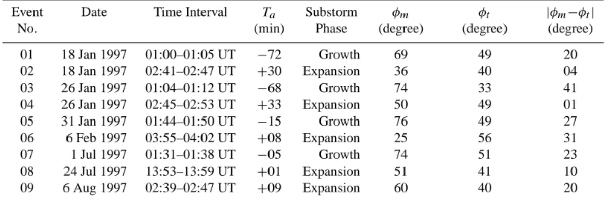
Table 1. Study events used.
Event Date Time Interval Ta Substorm φm φt |φm−φt|
No. (min) Phase (degree) (degree) (degree)
01 18 Jan 1997 01:00–01:05 UT −72 Growth 69 49 20 02 18 Jan 1997 02:41–02:47 UT +30 Expansion 36 40 04 03 26 Jan 1997 01:04–01:12 UT −68 Growth 74 33 41 04 26 Jan 1997 02:45–02:53 UT +33 Expansion 50 49 01 05 31 Jan 1997 01:44–01:50 UT −15 Growth 76 49 27 06 6 Feb 1997 03:55–04:02 UT +08 Expansion 25 56 31 07 1 Jul 1997 01:31–01:38 UT −05 Growth 74 51 23 08 24 Jul 1997 13:53–13:59 UT +01 Expansion 51 41 10 09 6 Aug 1997 02:39–02:47 UT +09 Expansion 60 40 20
Ta: Timing away from the expansion onset. Negative (Positive) means before (after) the onset.
φm: The orientation of the magnetic deflection vector deviated from the DMSP trajectory.
φt: The orientation of the two-cell aurora deviated from the DMSP trajectory.
magnetometer data, drift meter data have a baseline problem. The baseline is affected on the nightside by low total ion den-sity and the presence of H+ at mid-latitudes and by low to-tal ion density on the dayside. The best way to adjust the baseline is to subtract a straight line that connects between a point on the dusk side and a point on the dawn side (e.g. Shue and Weimer, 1994). However, data gaps do not enable us to do this straight line subtraction. Instead, we subtracted a constant value that was obtained from an average of elec-tric fields over 50–55◦. The coordinate system of IDM is different from that of SSM. The +X component is parallel to the spacecraft velocity vector. The +Z component is vertical away from the center of the Earth. The +Y component of the measured field is perpendicular to +X and +Z in the sense of a right-handed coordinate system. Thus, +Y is toward the dayside of the orbit plane.
All DMSP measurements were transformed into the fol-lowing coordinate system such that the +X component is in the direction of the spacecraft velocity vector, the +Y com-ponent is perpendicular to the +X comcom-ponent and points to-ward the nightside of the orbit plane, and the +Z component follows a right-handed rule.
3 Results
For demonstration purposes we will show four events which best represent the characteristics of the two-cell aurora. The first one is the 01:44–01:50 UT, 31 January 1997 event. We selected two consecutive LBH-long images at 01:46 and 01:49 UT which were closest to the period of this event, as shown in Fig. 2a. The images show the typical two-cell auro-ral feature. The white line on each image denotes the trajec-tory of the DMSP F12 spacecraft during the event, moving from the equatorward side of the aurora to the poleward side. The two ends of the line denote the locations of DMSP at the beginning and the end of the event. The orientation of the two-cell aurora determined by the tangent to the locus of
the maximum emission as one moves azimuthally along the region of auroral emissions was at an angle of ∼49◦ to the DMSP trajectory.
The +Y component of the magnetic field points toward the nightside of the orbit plane. The magnetic field disturbance equatorward of the auroral oval was almost zero, as shown in the black line in the By/Bx panel of Fig. 2b. This magnetic
field disturbance increased and then decreased significantly. Near the two-cell aurora, the magnetic field pattern shows a double sheet of field-aligned currents. A horizontal white (shaded) bar denotes the main upward region 1 (downward region 2) field-aligned current which we identified. It should be noted that we ignored some small-scale field-aligned rents which were embedded in the main field-aligned cur-rents. The X component of the magnetic field (Bx) was small
during the period, as shown in the blue line in the By/Bx
panel. The orientation of the magnetic deflection vector was estimated to be at an angle of ∼76◦to the DMSP trajectory.
It results in a 27◦difference between the orientations of the
magnetic deflection vector and the two-cell aurora.
The Vypanel shows that the convection reversal lay in the
upward region 1 field-aligned current, which is consistent with results of previous studies. The convection was anti-sunward in the polar cap and returned anti-sunward at lower lati-tudes on the dusk. This convection feature is consistent with the dusk-side portion of the typical two-cell convection pat-tern.
In this study we calibrated the peak DMSP electron energy flux with the peak auroral emission along the spacecraft’s trajectory because the location of the peak auroral emission is least affected by a wobble effect on the UVI images and sensitivity thresholds of the UVI instrument. Note that the wobble effect and sensitivity thresholds may introduce some uncertainty as to an identification of auroral boundaries, if we use a threshold (Brittnacher et al., 1999; Baker et al., 2000; Shue et al., 2001) or a ratio (Kauristie et al., 1999; Baker et al., 2000; Carbary et al., 2003) method.
60Ο 0 2 4 6 8 10 12 14 16 18 20 22 01:46 UT
a) Polar UVI
60Ο 0 2 4 6 8 10 12 14 16 18 20 22 01:49 UT 0.0 2.0 4.0 6.0 8.0 10.0 12.0 14.0 16.0 18.0 20.0 Photons cm−2 s−1b) DMSP SSIES and SSM
c) DMSP SSJ4
-400 0 400 By (nT) -400 0 400 Bx (nT) -1800 -900 0 900 1800 Vy (m/s) 9 13 8 12 LOG JE ELECTRONS IONS 2 4 2 4 LOG E AVE 2 3 4 ELEC 2 3 4 2 3 4 IONS 2 3 4 UT 01:44:00 01:44:35 01:45:11 01:45:47 01:46:23 01:46:59 01:47:35 01:48:11 01:48:47 01:49:23 01:49:59 MLAT 62.5 64.4 66.3 68.2 70.1 71.9 73.6 75.4 77.0 78.6 80.1 GLAT 50.0 52.0 54.1 56.1 58.1 60.2 62.2 64.2 66.1 68.1 70.0 GLONG 285.2 284.3 283.2 282.1 280.8 279.4 277.9 276.1 274.2 271.9 269.2 MLT 20:38 20:34 20:28 20:23 20:15 20:07 19:57 19:45 19:30 19:10 18:45 F12 97/31 Jan 31
LOG ENERGY (EV)
JHU/APL 5 10 3 8 ELEC ION E FLUXLOG
Fig. 2. A summary of observations for the 01:44–01:50 UT, 31 January 1997 event. (a) We selected two consecutive Polar UVI LBH-long
auroral images which were closest to the period of the event. The white line on each image marks the trajectory of the DMSP F12 spacecraft, moving from the equatorside of the aurora to the poleward side. The both ends of the line denote the locations of DMSP at the beginning and the end of the event. (b) The black (blue) curve in the magnetic field panel represents variations of the Y and X components of the magnetic
field produced by field-aligned currents. The vertical line in the By/Bxand convection (Vy) panels denotes the location of the peak energy
flux determined from (c) the DMSP electron energy flux data. The white (shaded) horizontal bar in the Vypanel represents the interval of
large-scale region 1 (region 2) field-aligned currents. Note that the +X component is in the direction of the spacecraft velocity vector. The
60Ο 0 2 4 6 8 10 12 14 16 18 20 22 01:32 UT
a) Polar UVI
60Ο 0 2 4 6 8 10 12 14 16 18 20 22 01:35 UT 0.0 2.5 5.0 7.5 10.0 12.5 15.0 17.5 20.0 22.5 25.0 Photons cm−2 s−1b) DMSP SSIES and SSM
c) DMSP SSJ4
-400 0 400 By (nT) -400 0 400 Bx (nT) -2000 -1000 0 1000 2000 Vy (m/s) 9 13 8 12 LOG JE ELECTRONS IONS 2 4 2 4 LOG E AVE 2 3 4 ELEC 2 3 4 2 3 4 IONS 2 3 4 UT 01:31:00 01:31:41 01:32:23 01:33:05 01:33:47 01:34:29 01:35:11 01:35:53 01:36:35 01:37:17 01:37:59 MLAT 62.4 64.6 66.9 69.1 71.3 73.4 75.5 77.5 79.3 81.1 82.5 GLAT 50.2 52.5 54.9 57.3 59.6 62.0 64.3 66.6 68.9 71.1 73.2 GLONG 287.7 286.6 285.3 283.9 282.4 280.6 278.6 276.2 273.4 270.0 265.8 MLT 21:09 21:04 20:58 20:51 20:42 20:31 20:18 20:00 19:36 19:03 18:17 F12 97/182 Jul 1
LOG ENERGY (EV)
JHU/APL 5 10 3 8 ELEC ION E FLUXLOG
Fig. 3. A summary of observations for the 01:31–01:38 UT, 1 July 1997 event. The format is the same as that for Fig. 2.
The electron energy flux reached its maximum value at 01:46:53 UT, as shown in Fig. 2c. The vertical line in the panel of By/Bxand Vydenotes the location of this maximum
value. The spectrogram displays an inverted-V discrete
elec-tron structure (Lin and Hoffman, 1979; Newell et al., 1996), occurring in the region 1 field-aligned current. Since the au-roral emission from LBH-long is proportional to the electron energy flux, the peak LBH-long and peak electron energy
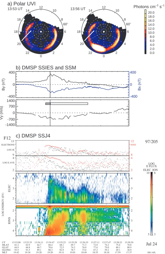
60Ο 0 2 4 6 8 10 12 14 16 18 20 22 13:53 UT
a) Polar UVI
60Ο 0 2 4 6 8 10 12 14 16 18 20 22 13:56 UT 0.0 2.0 4.0 6.0 8.0 10.0 12.0 14.0 16.0 18.0 20.0 Photons cm−2 s−1b) DMSP SSIES and SSM
c) DMSP SSJ4
-400 0 400 By (nT) -400 0 400 Bx (nT) -1400 -700 0 700 1400 Vy (m/s) 9 13 8 12 LOG JE ELECTRONS IONS 2 4 2 4 LOG E AVE 2 3 4 ELEC 2 3 4 2 3 4 IONS 2 3 4 UT 13:53:00 13:53:35 13:54:11 13:54:47 13:55:23 13:55:59 13:56:35 13:57:11 13:57:47 13:58:23 13:58:59 MLAT 61.2 62.9 64.7 66.4 68.1 69.7 71.3 72.8 74.2 75.6 76.8 GLAT 64.9 66.8 68.7 70.6 72.5 74.3 76.0 77.6 79.0 80.1 80.9 GLONG 93.5 91.5 89.1 86.3 82.9 78.7 73.6 67.2 59.2 49.1 36.9 MLT 19:42 19:36 19:28 19:20 19:11 19:01 18:49 18:35 18:18 17:59 17:37 F12 97/205 Jul 24
LOG ENERGY (EV)
JHU/APL 5 10 3 8 ELEC ION E FLUXLOG
Fig. 4. A summary of observations for the 13:53–13:59 UT, 24 July 1997 event. The format is the same as that for Fig. 2.
should be colocated. Thus, this indicates that the dusk-side branch of the two-cell aurora is discrete.
The second event is for 01:31–01:38 UT, 1 July 1997. The auroral intensity for this event was higher than the previous
event. The two closest LBH-long images to the period of the event were chosen, as shown in Fig. 3a. The DMSP space-craft traversed the dusk-side branch of the two-cell aurora at an angle of ∼51◦from the equatorward side of the auroral
oval during the event. Although there were several small-scale field-aligned currents shown in the Bypanel of Fig. 3b,
we identified only the main ones, as shown in the horizontal white and shaded bars for the upward region 1 and down-ward region 2 field-aligned currents, respectively. Bx was
small compared to By. The orientation of the magnetic
de-flection vector was found to deviate at an angle of ∼74◦ to the DMSP trajectory line. The orientations of the magnetic deflection vector and the two-cell aurora have a 23◦ differ-ence.
The Vypanel of Fig. 3b shows the ionospheric convection
for the 1 July 1997 event. The convection was anti-sunward in the polar cap and returned sunward at lower latitudes on the dusk side. This convection feature is consistent with the dusk-side portion of the typical two-cell convection pattern. The convection reversal lay in the region 1 field-aligned cur-rent.
The previous event shows a single inverted-V electron structure which was associated with the upward region 1 field-aligned current. However, in this event, there exists sev-eral discrete electron structures, as shown in Fig. 3c, which are consistent with several up-and-down changes in the mag-netic field disturbances. We selected the largest one to com-pare to the main regions of the field-aligned currents. It shows that the maximum precipitating electron flux occurred in the region 1 field-aligned current.
The third one is the 13:53–13:59 UT, 24 July 1997 event. We selected two consecutive LBH-long images at 13:53 and 13:56 UT for this period, as shown in Fig. 4a. The im-ages show that the typical two-cell auroral feature occurred at 13:53 UT and a substorm occurred at pre-midnight at 13:56 UT. The white lines on the images denote the trajec-tory of DMSP during the event, moving from the equator-ward side of the aurora to the poleequator-ward side at an angle of ∼41◦against the orientation of the two-cell aurora. The im-ages show a transition from the growth phase to the substorm expansion phase. In this case the convection reversal lay in the region 1 field-aligned current, as shown in Fig. 4b. Data gaps for electric fields over 50–65◦ may introduce an error in baseline removing. In this event we removed the baseline using an average of the electric fields over 65–66◦.
In this event there were several local energy flux peaks in the upward field-aligned currents, as shown in Fig. 4c. The largest peak is located at the region 1 field-aligned current. In this substorm transition event, Bxwas significantly large
comparing to By. It is apparent that Bx and By were
anti-correlated. The orientation of the magnetic deflection vector is estimated to be ∼51◦to the DMSP trajectory. The
dif-ference between the orientations of the magnetic deflection vector and the two-cell aurora is 10◦.
The substorm aurora fully developed during the fourth event (02:41–02:47 UT, 18 January 1997), as shown in Fig. 5a. Note that the two-cell aurora occurred prior to the substorm expansion onset (not shown). The DMSP F12 spacecraft moved from the equatorward side of the aurora to the poleward side, traversing the two-cell aurora at an an-gle of ∼40◦. We selected two consecutive LBH-long images
which were closest to the period of the event. The auroral images show that the substorm bulge reached the trajectory of DMSP.
The convection reversal lay in the upward region 1 field-aligned current, as shown in Fig. 5b. The antisunward con-vection appears in the polar cap and the sunward concon-vection appears at lower latitudes on the dusk side. This feature is consistent with the dusk-side portion of the typical two-cell convection pattern. The main large-scale region 1 and 2 field-aligned currents were identified and marked as the white and shaded horizontal bars, respectively.
Figure 5c shows that the electron energy flux had a signif-icant increase in the upward region 1 field-aligned currents, which was associated with the electron acceleration in the high altitude. As in the 24 July 1997 event, Bx and By are
anti-correlated. The orientation of the magnetic deflection vector is at an angle of ∼36◦to the DMSP trajectory. The orientations of the magnetic deflection vector and the two-cell aurora have a 4◦difference.
From the four events we have shown, it is found that there is an angular difference between the orientations of the mag-netic deflection vector and the two-cell aurora. We also cal-culated the angular difference for the other five events. The results have been summarized in Table 1. φm(φt) represents
the orientation of the magnetic deflection vector (the two-cell aurora) to the DMSP trajectory. The φt is 46±4◦during the
substorm growth phase, and 45±3◦during the substorm
ex-pansion phase. Since the difference of the two means is less than the uncertainties of the means, it indicates that the sub-storm expansion onset does not significantly change the ori-entation of the two-cell aurora. However, the φm is 73±1◦
during the substorm growth phase, and 44±6◦ during the substorm expansion phase, indicating that the substorm ex-pansion onset changes the orientation of the magnetic de-flection vector. The angular difference (|φm−φt|) is 28±5◦
during the substorm expansion, and 13±6◦during the sub-storm expansion phase. The change in the angular difference from the growth phase to the expansion phase is significant because this change is larger than the uncertainties of the two angular differences. Note that the uncertainty of any parame-ter used in this study was calculated by the standard deviation of the mean.
4 Discussion
In this study we investigate ionospheric characteristics of the two-cell aurora using multiple observations. The two-cell au-rora is referred to as a special auau-roral form identified from Polar UVI auroral images. The two-cell aurora is related to discrete particle precipitation structures near the poleward edge of the auroral oval. Thus, the two-cell aurora is nar-rower in latitude than the auroral oval. We believe that none of the Polar UVI auroral images can provide a pretty good outline of the auroral oval, due to the problem of sensitivity for auroral emissions. The best way to define the auroral oval is based on particle precipitation.
60Ο 0 2 4 6 8 10 12 14 16 18 20 22 02:43 UT
a) Polar UVI
60Ο 0 2 4 6 8 10 12 14 16 18 20 22 02:46 UT 0.0 2.5 5.0 7.5 10.0 12.5 15.0 17.5 20.0 22.5 25.0 Photons cm−2 s−1b) DMSP SSIES and SSM
c) DMSP SSJ4
-400 0 400 By (nT) -400 0 400 Bx (nT) -1600 -800 0 800 1600 Vy (m/s) 9 13 8 12 LOG JE ELECTRONS IONS 2 4 2 4 LOG E AVE 2 3 4 ELEC 2 3 4 2 3 4 IONS 2 3 4 UT 02:41:00 02:41:35 02:42:11 02:42:47 02:43:23 02:43:59 02:44:35 02:45:11 02:45:47 02:46:23 02:46:59 MLAT 63.3 65.0 66.7 68.4 70.1 71.7 73.3 74.9 76.3 77.6 78.9 GLAT 50.5 52.5 54.5 56.6 58.6 60.6 62.6 64.6 66.6 68.5 70.4 GLONG 270.8 269.9 268.8 267.6 266.4 264.9 263.4 261.6 259.5 257.1 254.4 MLT 20:16 20:10 20:03 19:56 19:46 19:36 19:23 19:08 18:50 18:28 18:01 F12 97/18 Jan 18
LOG ENERGY (EV)
JHU/APL 5 10 3 8 ELEC ION E FLUXLOG
Fig. 5. A summary of observations for the 02:41–02:47 UT, 18 January 1997 event. The format is the same as that for Fig. 2.
The discrete auroral arcs are embedded in the auroral oval. There are often several discrete arcs (1 to 10 km in latitudinal width) which occurred within the region 1 (100 to 400 km in latitudinal width) portion of the auroral oval. The discrete
arcs are commonly shown in a form of sheets which bend and twist into shapes that locally are significantly not aligned with the auroral oval.
The large-scale region 1 field-aligned current sheet is as-sumed to be aligned with the auroral oval. The assumption of “infinite current sheets” has been found to be quite good if the length to the end of the current sheet or the radius of the curvature of the current is 5 times greater than the width of the current sheet. The most common locations where the assumption breaks down are the noon and midnight sectors of the auroral zones.
Small-scale field-aligned currents are usually embedded in the large-scale region 1 field-aligned current. The small-scale field-aligned currents may not be exactly aligned with the large-scale region 1 field-aligned current. It is likely that the small-scale field-aligned currents are roughly aligned with visible auroral arcs. Thus, it is possible that these auro-ral arcs are not aligned with the auroauro-ral oval.
We have found that the orientations of the magnetic de-flection vector and the two-cell aurora are misaligned. If there is no variation in the field-aligned current or in the iono-spheric conductivity with respect to local time, the magnetic deflection vector must be parallel to the current sheet and the two-cell aurora. However, there are conductivity gradients, especially along the terminator. The current system can be changed by these gradients (Burke et al., 1994). If there are gradients in the strength of the field-aligned currents and/or in the conductivity in the auroral oval, as a function of local time, it is more likely that the magnetic deflection vector will not be aligned with the current sheet and the two-cell aurora. We have also found that the orientation of the magnetic deflection vector produced by the region 1 field-aligned cur-rent changed from the growth phase to the substorm expan-sion phase. We believe that the local time distributions of the field-aligned currents and conductivity gradients are im-portant keys to the understand physical processes underlying the change in the magnetic deflection vector from the growth phase to the substorm expansion phase. However, we have no data for the local time distributions of the field-aligned currents and conductivity gradients for these events, to eval-uate this aspect.
From this study it is found that the uncertainty of the ori-entation of the magnetic deflection vector during the storm expansion phase is larger than that during the sub-storm growth phase. Loops and surges at the auroral region in the evening sector during the expansion phase may add more variations to the orientation of the magnetic deflection vector. Moreover, the magnetic deflection vector is also in-fluenced by the region 2 field-aligned current, even if DMSP is crossing field lines threaded by the region 1 field-aligned current. Enhanced region 2 field-aligned current during the substorm expansion may alter the orientation of the magnetic deflection vector.
An important result of this study is that there is a change in the orientation of the magnetic deflection vector in a transi-tion from the substorm growth phase to the expansion phase. One may question how long before the expansion onset, or into the expansion phase, had the activity proceeded at the time of the DMSP pass. To address this concern, we also calculated the timing of the DMSP pass away from the
sub-storm expansion onset (Ta) for each of the nine events, as
listed Table 1. A negative (positive) sign in Ta denotes that
the DMSP pass occurred before (after) the substorm expan-sion onset. A comparison of φm to Ta has shown that the
orientation of the magnetic deflection vector is independent of the timing of the DMSP pass away from the substorm ex-pansion onset.
We cannot determine whether the two-cell aurora is dis-crete or diffuse from Polar UVI auroral images alone. DMSP particle precipitation data have shown one or several discrete electron structures associated with the dusk-side branch of the two-cell aurora. This result is consistent with the one obtained by Winningham et al. (1979), who studied particle precipitation and magnetometer data for the evening sector and found that discrete particle structures, which are associ-ated with the boundary plasma sheet, appeared at the pole-ward edge of the eastpole-ward electrojet.
Lyons et al. (2002) studied the pre-onset and expansion-phase auroral arcs using the Canadian Auroral Network for the Open Program Unified Study (CANOPUS) meridian-scanning photometer and all-sky imager observations. They found that one or more arcs are seen across the sky through-out the growth phase prior to the substorm expansion onset. This result supports our results that one or several precipita-tion regions are associated with the dusk-side branch of the two-cell aurora. They also found that the auroral breakup often occurs along a thin arc that forms equatorward of all growth phase arcs a few minutes prior to the onset, revealing the importance of a study of growth phase auroras, in order to understand substorm expansion onsets.
Shue et al. (2002) did not examine any convection data before they named the aurora the two-cell aurora. In this study, we actually examined DMSP ion drift meter data and confirmed that the convection was anti-sunward in the po-lar cap and was returned sunward at lower latitudes on the dusk. This convection feature is consistent with the dusk-side portion of the typical two-cell convection pattern. Note that satellite observations (e.g. Heppner and Maynard 1987) and many radar observations showed that sunward convection ex-ists all the time, even under northward IMF in the auroral zone and anti-sunward convection “just” poleward of it. One may think that our statement above is not completely justi-fied. However, the DMSP ion drift meter data show the anti-sunward convection “not just” poleward of the anti-sunward con-vection, but extending deep in the polar cap. We also exam-ined convection maps on Super Dual Auroral Radar Network (SuperDARN) data. We found that all of the maps showed a two-cell convection pattern, but none of them had sufficient data coverage. Therefore, all the SuperDARN patterns are most likely produced by an empirical model, which is based on the IMF By/Bz.
5 Conclusions
In this study we utilize Polar UVI auroral images and DMSP particle precipitation, convection, magnetic field data, to
investigate characteristics of the dusk-side branch of the two-cell aurora. A portion of our results derived from this study confirm the previous ones, but we have the following new findings:
1. The average angle between the orientation of the two-cell aurora and the DMSP trajectory line is 46±4◦ (45±3◦) during the substorm growth (expansion) phase. This indicates that the substorm expansion onset does not significantly change the orientation of the dusk-side branch of the two-cell aurora.
2. A change in the orientation of the magnetic deflection vector associated with the dusk-side branch of the two-cell aurora occurred in a transition from the growth phase to the substorm expansion phase. The orienta-tion of the magnetic deflecorienta-tion vector with respect to the DMSP trajectory is 73±1◦during the substorm growth
phase, and 44±6◦during the substorm expansion phase. 3. The angular difference between the orientation of the magnetic deflection vector and the orientation of the two-cell aurora is 28±5◦ during the substorm growth phase, and 13±6◦during the substorm expansion phase.
Acknowledgements. This work was supported in part by
tional Science Council grant NSC-93-2111-M-008-010 and tional Space Organization grant 94-NSPO(B)-SP-FA07-02 to Na-tional Central University, and in part by NaNa-tional Science Founda-tion grant ATM-0001621 to The Johns Hopkins University Applied Physics Laboratory. We thank G. K. Parks for providing us with Polar auroral images. We also thank A. J. Lazarus for the use of Wind plasma data, and R. P. Lepping for the use of Wind magnetic field data.
The Editor in Chief thanks N. Nishitani and another referee for their help in evaluating this paper.
References
Baker, J. B., Clauer, C. R., Ridley, A. J., Papitashvili, V. O., Britt-nacher, M. J., and Newell, P. T.: The nightside poleward bound-ary of the auroral oval as seen by DMSP and the Ultraviolet Im-ager, J. Geophys. Res., 105, 21 267–21 280, 2000.
Baker, K. B. and Wing, S.: A new magnetic coordinate system for conjugate studies at high latitudes, J. Geophys. Res., 94, 9139– 9143, 1989.
Brittnacher, M., Elsen, R., Parks, G., Chen, L., Germany, G., and Spann, J.: A dayside auroral energy deposition case study using the Polar Ultraviolet Imager, Geophys. Res. Lett., 24, 991–994, 1997.
Brittnacher, M., Fillingim, M., Parks, G., Germany, G., and Spann, J.: Polar cap area and boundary motion during substorms, J. Geo-phys. Res., 104, 12 251–12 262, 1999.
Burke, W. J., Machuzak, J. S., Maynard, N. C., Basinska, E. M., Erickson, G. M., Hoffman, R. A., Slavin, J. A., and Hanson, W. B.: Auroral ionospheric signatures of the plasma sheet boundary in the evening sector, J. Geophys. Res., 99, 2489–2499, 1994. Carbary, J. F., Sotirelis, T., Newell, P. T., and Meng, C.-I.:
Auro-ral boundary correlations between UVI and DMSP, J. Geophys. Res., 108, 1018, doi:10.1029/2002JA009378, 2003.
Clauer, C. R.and Kamide, Y.: DP 1 and DP 2 current systems for the March 22, 1979 substorms, J. Geophys. Res., 90, 1343–1354, 1985.
Dungey, J. W.: Interplanetary magnetic field and auroral zones, Phys. Rev. Lett., 6, 47–49, 1961.
Germany, G. A., Torr, M. R., Torr, D. G., and Richards, P. G.: Use of FUV auroral emissions as diagnostic indicators, J. Geophys. Res., 99, 383–388, 1994.
Hardy, D. A., Schmitt, L. K., Gussenhoven, M. S., Marshall, F. J., Yeh, H. C., Schumaker, T. L., Huber A., and J. Pantazis: Precipi-tating electron and ion detectors (SSJ/4) for the block 5D/flights 6–10 DMSP satellites: Calibration and data presentation, Rep. AFGL-TR-84-0317, Air Force Geophys. Lab., Hanscom Air Force Base, MA, 1984.
Heelis, R. A., Winningham, J. D., Hanson, W. B., and Burch, J. L.: The relationships between high-latitude convection reversals and the energetic particle morphology observed by Atmosphere Explorer, J. Geophys. Res., 85, 3315–3324, 1980.
Heppner, J. P. and Maynard, N. C.: Empirical high-latitude electric field models, J. Geophys. Res., 92, 4467–4489, 1987.
Iijima, T. and Potemra, T. A.: The amplitude distribution of field-aligned currents at northern high latitudes observed by Triad, J. Geophys. Res., 81, 2165–2174, 1976.
Kamide, Y.: The two-component auroral electrojet, Geophys. Res. Lett., 9, 1175–1178, 1982.
Kamide, Y. and Kokubun, S.: Two-component auroral electrojet: Importance for substorm studies, J. Geophys. Res., 101, 13 027– 13 046, 1996.
Kauristie, K., Weygand, J., Pulkkinen, T. I., Murphree, J. S., and Newell, P. T.: Size of the auroral oval: UV ovals and precipitation boundaries compared, J. Geophys. Res., 104, 2321–2331, 1999. Lin, C. S. and Hoffman, R. A.: Characteristics of the inverted V
event, J. Geophys. Res., 84, 1514–1524, 1979.
Liou, K., Newell, P. T., Meng, C.-I., Brittnacher, M., and Parks, G.: Characteristics of the solar wind controlled auroral emissions, J. Geophys. Res., 103, 17 543–17 557, 1998.
Lyons, L. R., Voronkov, I. O., Donovan, E. F., and Zesta, E., Rela-tion of substorm breakup arc to other growth-phase auroral arcs: J. Geophys. Res., 107, 1390, doi:10.1029/2002JA009317, 2002. Marklund, G. T., Blomberg, L. G., Stasiewicz, K., Murphree, J. S., Pottelette, R., Zanetti, L. J., Potemra, T. A., Hardy, D. A., and Rich, F. J.: Snapshots of high-latitude electrodynamics us-ing Vikus-ing and DMSP F7 observations, J. Geophys. Res., 93, 14 479–14 492, 1988.
Meng, C.-I.: Electron precipitations and polar auroras, Space Sci. Rev., 22, 223–300, 1978.
Newell, P. T., Lyons, K. M., and Meng, C.-I.: A large survey of electron acceleration events, J. Geophys. Res., 101, 2599–2614, 1996.
Nishida, A.: Geomagnetic DP 2 fluctuations and associated magne-tospheric phenomena, J. Geophys. Res., 73, 1795–1803, 1968. Rich, F. J. and Hairston, M. R.: Large-scale convection patterns
observed by DMSP, J. Geophys. Res., 99, 3827–3844, 1994. Rich, F. J., Hardy, D. A., and Gussenhoven, M. S.: Enhanced
ionosphere-magnetosphere data from the DMSP satellites, Eos Trans. AGU, 66, 513–516, 1985.
Shue, J.-H. and Weimer, D. R.: The relationship between iono-spheric convection and magnetic activity, J. Geophys. Res., 99, 401–415, 1994.
Shue, J.-H., Kamide, Y., Elphinstone, R. D., and Nishitani, N.: In-tense growth phase events of substorms, J. Geophys. Res., 105, 5357–5371, 2000.
Shue, J.-H., Newell, P. T., Liou, K., and Meng, C.-I.: Influence of interplanetary magnetic field on global auroral patterns, J. Geo-phys. Res., 106, 5913–5926, 2001.
Shue, J.-H., Newell, P. T., Liou, K., Meng, C.-I., Kamide, Y., and Lepping, R. P.: Two-component auroras, Geophys. Res. Lett., 29, doi:10.1029/2002GL014657, 2002.
Smiddy, M., Burke, W. J., Kelley, M. C., Saflekos, N. A., Gussen-hoven, M. S., Hardy, D. A., and Rich, F. J.: Effects of high-latitude conductivity on observed convection electric fields and Birkeland currents, J. Geophys. Res., 85, 6811–6818, 1980. Strickland, D. J., Daniel Jr., R. E., Jasperse, J. R., and Basu,
B.: Transport-theoretic model for the electron-proton-hydrogen atom aurora, 2. Model results, J. Geophys. Res., 98, 21 533– 21 548, 1993.
Torr, M. R., Torr, D. G., Zukic, M., et al.: A far ultraviolet imager for the international solar-terrestrial physics mission, Space Sci. Rev., 71, 329–383, 1995.
Winningham, J. D., Kawasaki, K., and Rostoker, G.: Energetic par-ticle precipitation into the high-latitude ionosphere and the au-roral electrojets, 1. Definition of electrojet boundaries using en-ergetic electron spectra and ground-based magnetometer data, J. Geophys. Res., 84, 1993–2005, 1979.