Continuous High-Yield Production of Vertically Aligned
Carbon Nanotubes on 2D and 3D Substrates
Roberto Guzman de Villoria1*, A. John Hart 2, Brian L. Wardle1
1Department of Aeronautics and Astronautics, Massachusetts Institute of Technology, 77
Massachusetts Avenue, Cambridge, MA 02139, USA
2Department of Mechanical Engineering, University of Michigan, Ann Arbor, MI.
*Address correspondence to rguzman@mit.edu
ABSTRACT
Vertically aligned carbon nanotubes (VACNTs) have certain advantages over bulk CNT (carbon nanotubes) powders and randomly-oriented CNT mats for applications in flexible electronic devices, filtration membranes, biosensors and multifunctional aerospace materials. Here, a machine and a process to synthesize VACNTs in a continuous manner are presented showing uniform growth on 2D and 3D substrates, including alumina fibers, silicon wafer pieces, and stainless steel foils. Aligned multi-walled carbon nanotubes (MWNT) are synthesized at substrate feed rates of up to 6.8 cm/min, and the CNTs reach up to 40 m in length depending on residence time in the reactor. In addition to the aligned morphology indicative of high yield growth, transmission electron microscopy (TEM) and Raman spectroscopy reveal that the CNTs are of comparable quality to CNTs grown via a similar batch process. A significant reduction in time, reaction products, gases, and energy is demonstrated relative to batch processing, paving the way for industrial production of VACNTs.
KEYWORDS: carbon nanotubes, chemical vapour deposition, efficiency, manufacturing,
composites
Continuous production of vertically aligned carbon nanotubes (VACNTs) is needed due to their potential electrical,1,2 mechanical,3-5 and thermal applications,6 among others. Despite intensive studies of VACNTs synthesis, batch processing is still the only route demonstrated in the literature to growth VACNTs.7-9 While several patents and conference presentations indicate schemes to produce VACNTs continuously,10,11 to our knowledge no continuous processing results have been presented in the open literature. Among all the techniques available to
synthesize CNTs, only catalytic thermal chemical vapor deposition (CVD) has been widely used to grow dense and long VACNT arrays, or “forests”, of micrometers to millimeters in height (length).12 In catalytic thermal CVD, a catalyst and a gas mixture, both at high temperature, are needed for CNT growth. Investigations of the many parameters involved in CVD growth of VACNTs including the catalyst, the feedstock chemistry, the flow rate and residence time, pressure, and temperature, have enabled control of the diameter,13 density,14 and length of the CNTs.15 Large area VACNT arrays up to an A4 substrate size were recently demonstrated.16 Nevertheless, these studies only demonstrated batch processing, where CNTs were grown on a static substrate placed inside a CVD furnace. A continuous process for VACNT manufacturing requires a mechanism to continuously introduce a catalyst-coated substrate, pass the substrate through a processing environment, and then remove the finished product.17,18 A few studies of CNT growth on moving substrates have been made in open19,20 and closed21 reactors. In an open-air reactor configuration, a quartz substrate was moved relative to a laser spot that acted as the heater.22 In our earlier work, using a closed reactor system, the substrate was placed on a moving platform that oscillated back and forth, and growth of cm2 area CNT forests with up to 0.9 mm length was demonstrated.21
One of the main motivations for continuous VACNT production is to reduce the time, consumption of gases (both inert and active), and energy usage relative to batch processing methods. As an example, in our standard batch process to grow a CNT forest of 0.5 mm length (5 minutes), only 2% of the time spent is used for CNT growth, and 9% of the time is used to anneal the catalyst before growth. The remainder of the time is spent heating and cooling the furnace and flushing the reactor with an inert gas before and after the process. Similarly, most of the energy is consumed in heating the furnace enclosure (tube, coils, insulation), and not by the growth process itself.
In the present work, we have developed a system for continuous production of vertically aligned CNTs (Figure 1a). The system can easily be reconfigured to accommodate woven fiber substrates, silicon wafer pieces, and flexible metal foils. Compared to our standard batch process, identical VACNT films can be grown 26 times faster, reducing consumption of He and H2 by 95% and 89% respectively. All these characteristics make this system interesting from an
environmental, energetic and industrial point of view.
RESULTS AND DISCUSSION
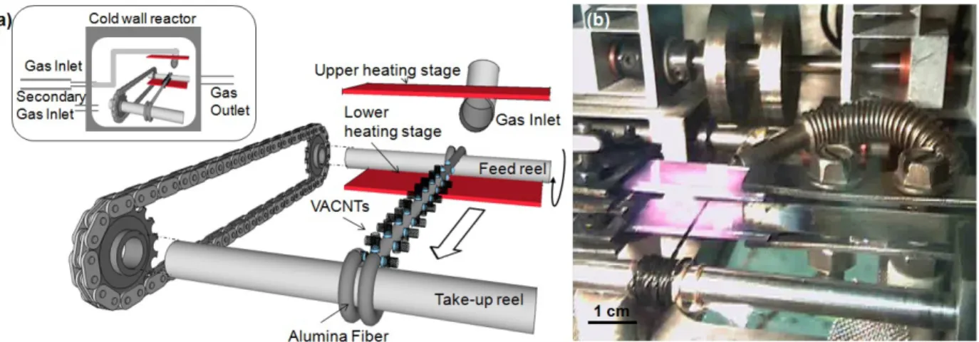
Continuous System. Our system has three main elements (Figure 1a): a conveyance mechanism
to continuously move the substrate, a dual platform resistive heater through which the substrate is conveyed, and a inlet pipe that directs the reactant mixture to the substrate. All these elements are confined in a closed aluminum chamber that has two borosilicate glass windows to enable visualization24,25 during growth. The chamber has several ports for the gas inlets and outlets, and connects the convenyance mechanism to the external actuator (Figure S1). The chamber and ports are sealed by o-rings and standard threaded fittings.
The conveyance mechanism is composed of take-up and feed reels, between which the substrate is placed. The feed reel is moved by a computer-controlled actuator (Hi-T-Drive RH-8-6006) placed outside the chamber, and the take-up reel is activated by the movement of the feed reel. The system can be configured for conveyance of 2D or 3D substrates, including fibers, rigid wafer pieces, and flexible foils. The dual platform resistive heater is comprised of upper and lower heaters made of highly-doped silicon wafers21,23 in a “toaster” configuration. The substrate is heated primarily by radiation and convection in the two heaters. The temperature of the bottom heating element is measured through one of the borosilicate glass windows using a calibrated infrared sensor (Exergen 3AMF). No special mechanical or temperature restrictions are necessary for the box or the windows, as the CNTs were grown at ambient pressure and the substrates are heated locally.
The gas inlet is made of a flexible stainless steel hose, positioned to direct the flow to the heated area in the “toaster”, thereby supplying the feedstock under conditions necessary for high-yield synthesis. To facilitate CNT growth, we first “preheat” the feedstock by flowing the mixture through a 25.4 mm diameter quartz tube furnace (Lindberg Blue/M), before it reaches the cold wall reactor.21,26 This procedure allows the separation of thermal pretreatment of the feedstock from the reaction chamber, generating a multitude of hydrocarbons.27
By passing the various substrates (coated with or containing catalyst) through the space between the heated surfaces of the “toaster” we achieved continuous VACNT growth. In all cases the substrate was pretreated (also continuously in the same reactor) under H2 to condition the
catalyst, before the growth process was conducted. This procedure was also previously established and refined as a serial process in a batch furnace (see Supporting Information).
VACNT Growth on Fiber Substrates. Radially-aligned CNTs are grown in situ on the surface
of fibers, such as alumina,28,29 which have been shown to provide significantly enhanced three-dimensional mechanical reinforcement and multifunctional properties in composite materials.29 The continuous system was first tested using alumina fibers, and once the growth conditions were optimized to give VACNT growth on this substrate, the same parameters were used for the other substrates. 40 cm long alumina fiber bundles/tows coated with iron nitrate28 were fixed to both reels and wound around the take-up reel, passing through the heater stage (Figure 1b). Details of the growth process parameters can be found in the Methods section.
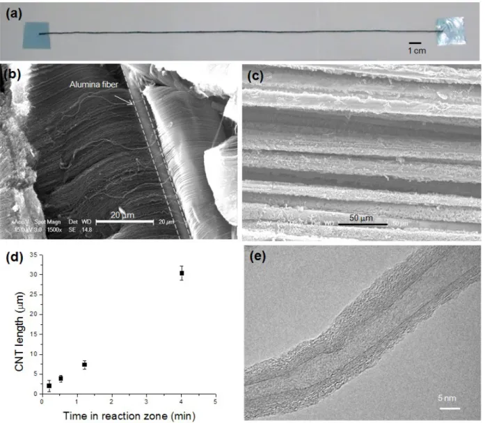
To study the effect of substrate velocity on the CNT length, the alumina fibers were fed continuously at different rates (0.3, 1.1, 2.5, 6.8 cm/min). A 34 cm long stretch of fiber, grown at 2.5 cm/min, is shown in Figure 2a. SEM images (Philips XL30) were taken at different spots of the alumina fibers, indicating a homogeneous CNT distribution along the fibers. We observed a “Mohawk” type of organized CNTs for the slowest velocities (Figure 2b), along with a radially-uniform “annulus” CNT distribution for the fastest velocities that yields the shortest CNTs (Figure 2c). These morphologies have been observed and documented previously on batch-processed CNTs on fibers and associated with differences in catalyst conditioning and growth parameters.30 The VACNT length on the fibers is linearly proportional to the time the substrate spends in the heater zone (Figure 2d).
A practical manufacturing challenge was to maintain the morphology of the CNTs on the fiber, despite the winding operation during the continuous growth process. Even though the fibers are wound around a small-diameter spool (6.5 mm diameter), we discovered that the CNTs remain adhered to the alumina fibers, suggesting that the adhesion between the CNTs and alumina fibers was adequate for this type of take-up reel. In some outer regions of the wound fibers, particularly areas that were physically in contact with the steel take-up reel, the aligned CNTs were deformed; however, the CNTs on the inner fibers were not deformed, maintaining the characteristic “fuzzy” fiber structure.
CNTs grown on alumina fibers at 0.33 cm/min were inspected using TEM (JEOL 2010, Acc. Voltage 200.0 KV) (Figure 2e) yielding CNTs with an average outside diameter of 10 nm with 9-10 walls (Figure S2). We observed an outer amorphous carbon coating caused by the pyrolitic decomposition of the reactant mixture, which is consistent with the Raman spectra observations (Figure S3). This amorphous carbon layer can be removed by air oxidation after growth, and also reduced by tuning the preheater conditions (temperature and residence time) and the growth conditions, though neither of these treatments was attempted in this study. The structure of the MWNTs observed by TEM and Raman is similar to the structure of CNTs grown on alumina fibers in our batch furnace30 using optimized conditions, and also similar to CNTs grown in the same batch furnace using parameters that mimic those in the continuous system (see Supporting Information).
Raman spectra were collected to further analyze the quality of the CNTs. All the spectra had a D and G band, characteristic of CNTs including MWNTs as synthesized here.31,32 For the alumina fibers growth at different velocities, the ratio between the ID/IG was ≈1.3±0.1 and relatively independent of the velocity of substrate motion (Figure S3). Compared to both our optimized batch process30 and the batch-style emulation of the continuous process (see Supporting Information), the CNTs produced on alumina fibers have a slightly larger ID/IG ratio. We associate this with amorphous carbon deposits on the CNT walls, due the broad spectrum of hydrocarbons produced by the preheater and the elevated temperature of the silicon heating elements.33.
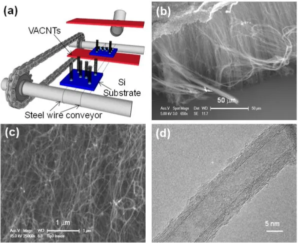
Growth on Rigid Substrates. After completing the CNT growth studies on alumina fibers, we
reconfigured the system to study growth on 2D flat substrates. With the new configuration we first studied growth on silicon wafers coated with catalyst by e-beam evaporation (1 nm Fe/10 nm Al2O3)21. To do so, two stainless steel wires of 0.127 mm diameter served as a conveyor belt (Figure 3a) for the Si wafer growth substrate. The 1x1cm2 Si wafer pieces were placed in series on top of the wires, just before the heater stage. In this case, the wafers were fed at 1.3 cm/min to grow VACNT forests of 60 μm length (Figure 3b). We observed the aligned yet wavy CNT morphology by SEM4,34 (Figure 3c), which is consistent with batch processing of VACNTs on silicon substrates (see SI for further comparison). For the continuous growth on silicon, the VACNTs have a concentric layer structure (10-12 walls) (Figure 3d) and an average outside
diameter of 16 nm (Figure S2). Raman spectra were collected directly from the forest to assess CNT quality, showing the typical spectra of MWNT arrays (Figure S3) with ID/IG ≈1.2.
Growth on Flexible Foils. One of the main drawbacks of using silicon wafers for continuous
processing, as opposed to the flexible substrate, is their stiffness. It is not possible to bend or fold a standard Si wafer, which constricts the design of any machine to grow VACNTs continuously over large areas. Several groups have grown CNTs on flexible substrates such as aluminum foil,35 stainless steel36 or metallic alloys,37 on which a metal catalyst has been previously deposited. Recent work38 shows the possibility of growing VACNTs on stainless steel substrates without introducing a catalyst. Only a thermal treatment in air to oxidize the surface of the stainless steel is necessary for the metal alloy substrate to serve as a catalyst for CNT growth, utilizing the metal species contained in the steel. This thermal treatment allows growth of CNTs directly on the surface of a stainless steel film, making it possible to recirculate the stainless steel foil as shown in Figure 4a. In order to grow VACNTs continuously on a flexible foil of stainless steel, a 1 cm wide (Trinity Brand Industries, SN-x, 0.0127 mm thick) foil was rolled and joined to form a conveyor belt, passing through both reels and the heater stage (Figure 4a). The belt was tightly stretched across both reels to minimize the effect of the temperature-induced dilatations, as any misalignment might buckle the film when high temperatures are applied (Figure 4b). Prior to CNT growth, the stainless steel foil was cleaned with acetone and isopropanol and then exposed to air at 450±75oC at 1.3 mm/min. Next, the reactor was closed, the catalyst pretreated, and CNTs grown at 1.3 mm/min substrate velocity.
Uniform VACNT forests of 5 μm length were produced using the steel foil as substrate, (Figure 4b), showing the characteristic waviness of VACNTs (Figure 4c). Metal catalyst seeds were found at different spots along the CNT length, indicating that the nanoparticle seeds are not well attached to the substrate (Figure 4d). Further research needs to be done to analyze this co-substrate/catalyst system, and particularly the role of the oxidation process on nanoparticle formation on the surface of the alloy and the role of other alloying elements. TEM also reveals that the steel-substrate grown CNTs have a typical MWNT concentric layer structure (8-10 walls) (Figure 4e) and an average diameter of 25 nm. A large number of CNTs were examined and were found to have a diameter ranging from 15-45 nm (Figure 4f), including some “bamboo” CNTs with septa that divide the filament into a series of connected lobes. The
characteristic Raman spectra of MWNTs were obtained (Figure S4). In this case, ID/IG was 1.6, indicating the presence of amorphous carbon, as well as a generally lower quality of CNTs grown on stainless steel compared to the catalyst-coated substrates.
CONCLUSIONS
We demonstrated a high-yield VACNT growth on various substrates using a continuous process. Well-aligned VACNTs were obtained on all the substrates used including alumina fibers, stainless steel foil, and silicon wafers. In the case of growth on alumina fibers (3D substrates), we have demonstrated a regime of feed rates where the CNT growth is linearly proportional to residence time in the heater. CNTs are grown uniformly on the whole surface of the fibers, both inner and outer fibers, obtaining similar high-yield aligned morphology as in a batch process. Such aligned-CNT growth on fibers is very desirable to create “fuzzy fiber” hybrid advanced composites with superior mechanical and multifunctional properties.29 CNT growth on 2D substrates such as stainless steel foils and silicon wafers also showed similar high-yield results. It is also interesting to note that in the case of the stainless steel foil, the substrate itself serves as the catalyst. All these characteristics make the system easily scalable to larger production of dense VACNT forests.
This continuous fabrication approach is potentially extensible to other CVD processes, such as growth of graphene or semiconductor nanowires39 upon appropriate modification to the process conditions. The ability to tailor temperature exposure via the feed rate may have applications in nanoparticle preparation in general. Future work will focus on control of process parameters to enable higher quality CNT synthesis at faster velocities, delivery efficient precursors to the substrate without preheating, and translating this concept to large-scale production.
METHODS
VACNT Synthesis. Once the reactor was sealed, all the lines (Tygon 2075 tubing, 0.635 cm
inner diameter) connected to the system were flushed for 8 mins. followed by 10 additional minutes of helium to displace trapped air from the system. After ten minutes, the heater stage and the preheater ramped to 820 °C and 775 °C, respectively, over 5 minutes with 400/72 sccm of H2/He flowing. During the entire process, helium was added by a secondary line to maintain an
inert atmosphere and keep the walls of the reactor cold. Once the temperature was reached, the substrate was pulled through the heaters by the take-up reel, conditioning the substrate to form metallic nanoparticles.40,14 After pretreatment, the reactant mixture of He/H
2/C2H4 (72/400/200 sccm) was introduced and the direction of rotation was changed to proceed with VACNT growth by pulling the substrate through the reactor from the take-up reel to the feed reel (Figure 1b). Once VACNTs were grown, the motor was stopped and the system was cooled down to room temperature under helium to purge any reactive gases. The CNT growth process can be recorded visually directly through the front window.21 Cleaning of the system is not needed between growths because of the special advantages of using a cold wall reactor. A scheme of the gas inlet and outlet system is available as supporting information (Figure S1).
Raman Spectroscopy. The quality of the samples was analyzed by Raman spectroscopy. Results
are shown in the Supporting information. For the alumina fibers and silicon wafer VACNT growth, Raman spectra were collected directly using a Hololab 5000R Raman spectrometer (ex=785 nm, 65 μm excitation fiber, 100μm collection optical fiber, 10x objective, 23.4 mW, 120 s collection time). For the stainless steel film VACNT growth, VACNTs were dispersed in acetone for 5 minutes in an ultrasonic bath, and a drop of the solution was deposited on a glass slide coated with gold. Once the solvent was evaporated, Raman spectra were collected using the same conditions as described above.
Acknowledgements
This work was supported by the National Science Foundation Nanomanufacturing Program (CMMI-0800213) and Airbus S.A.S., Boeing, Embraer, Lockheed Martin, Saab AB, Spirit AeroSystems, Textron Inc., Composite Systems Technology, Hexcel, and TohoTenax through MIT’s Nano-Engineered Composite aerospace STructures (NECST) Consortium. The authors would like to thank S. Figueredo, A. Slocum, S. A. Steiner III for early discussions and work on the cold-wall reactor. R.G.V. thanks R. Mitchell (MIT CMSE) for TEM imaging assistance, T. McLure for Raman assistance, M. Levine and S. Wicks for critical reading of the manuscript, W.-S. Kim for his discussions on the stainless-steel batch process, and D. Robertson and T. Billings (MIT Aero/Astro) for all their help and discussions regarding machining and fabrication. This work made use of the Shared Experimental Facilities supported in part by the MRSEC Program of the National Science Foundation under award number DMR – 0819762.
Supporting Information Available: Cross-section of the continuous growth chamber, details of the study to decouple the pretreatment step from VACNT growth in a batch system, outer diameter distribution of the CNTs grown on alumina fibers and on silicon wafers, Raman spectroscopy of CNTs grown on different substrates and at different velocities, and details of the batch system VACNT growth processes to emulate the continuous growth conditions.
REFERENCES AND NOTES
1. Kang, S. J.; Kocabas, C.; Kim, H.; Cao, Q.; Meitl, M. A.; Khang, D.; Rogers, J. A. Printed Multilayer Superstructures of Aligned Single-Walled Carbon Nanotubes for Electronic Applications. Nano Lett. 2007, 7, 3343-3348.
2. Tsai, T. Y.; Lee, C. Y.; Tai, N. H.; Tuan, W. H. Transfer of Patterned Vertically Aligned Carbon Nanotubes onto Plastic Substrates for Flexible Electronics and Field Emission Devices. Appl. Phys. Lett. 2009, 95, 013107-3.
3. Blanco, J.; Garcia, E.; Guzman de Villoria, R.; Wardle, B. Limiting Mechanisms in Mode I Interlaminar Toughness of Composites Reinforced with Aligned Carbon Nanotubes. J. Compos. Mater. 2009, 43, 825-841.
4. Cebeci, H.; Guzman de Villoria, R.; Hart, A. J.; Wardle, B. L. Multifunctional Properties of High Volume Fraction Aligned Carbon Nanotube Polymer Composites with Controlled Morphology. Compos. Sci. Technol. 2009, 69, 2649-2656.
5. Zhang, M.; Atkinson, K. R.; Baughman, R. H. Multifunctional Carbon Nanotubes Yarns by Downsizing an Ancient Technology. Science 2004, 306, 1358-1361.
6. Choi, W.; Hong, S.; Abrahamson, J. T.; Han, J.; Song, C.; Nair, N.; Baik, S.; Strano, M. S. Chemically Driven Carbon-Nanotube-Guided Thermopower Waves. Nat. Mater. 2010, 9, 423-429.
7. Chen, H.; Roy, A.; Baek, J.; Zhu, L.; Qu, J.; Dai, L. Controlled Growth and Modification of Vertically-Aligned Carbon Nanotubes for Multifunctional Applications. Mater. Sci. Eng. R 2010, 70, 63-91.
8. Nessim, G. D. Properties, Synthesis, and Growth Mechanisms of Carbon Nanotubes with Special Focus on Thermal Chemical Vapor Deposition. Nanoscale 2010, 2, 1306-1323.
9. Terranova, M. L.; Sessa, V.; Rossi, M. The World of Carbon Nanotubes: An Overview of CVD Growth Methodologies. Chem. Vap. Deposition 2006, 12, 315-325.
10. Nakayama, Y.; Inazumi, C.; Shiozaki, H.; Fujita, D. Conductive Material Using Carbon Nano-Tube, and Manufacturing Method Thereof, European Patent, EP 1 489 630 A1, July 15, 2004 11. Nakayama, Y.; Zhang, M.; Harada, A. Method for Manufacturing Carbon Nanocoils, US Patent,
US 2003/0012721 A1, July 10, 2001
12. Hata, K.; Futaba, D. N.; Mizuno, K.; Namai, T.; Yumura, M.; Iijima, S. Water-Assisted Highly Efficient Synthesis of Impurity-Free Single-Waited Carbon Nanotubes. Science 2004, 306, 1362-1364.
13. Yamada, T.; Namai, T.; Hata, K.; Futaba, D. N.; Mizuno, K.; Fan, J.; Yudasaka, M.; Yumura, M.; Iijima, S. Size-Selective Growth of Double-Walled Carbon Nanotube Forests from
Engineered Iron Catalysts. Nat. Nanotechnol. 2006, 1, 131-136.
14. Nessim, G. D.; Hart, A. J.; Kim, J. S.; Acquaviva, D.; Oh, J.; Morgan, C. D.; Seita, M.; Leib, J. S.; Thompson, C. V. Tuning of Vertically-Aligned Carbon Nanotube Diameter and Areal Density through Catalyst Pre Treatment. Nano Lett. 2008, 8, 3587-3593.
15. Eres, G.; Kinkhabwala, A. A.; Cui, H.; Geohegan, D. B.; Puretzky, A. A.; Lowndes, D. H. Molecular Beam-Controlled Nucleation and Growth of Vertically Aligned Single-Wall Carbon Nanotube Arrays. J. Phys. Chem. B 2005, 109, 16684-16694.
16. Yasuda, S.; Futaba, D. N.; Yamada, T.; Satou, J.; Shibuya, A.; Takai, H.; Arakawa, K.; Yumura, M.; Hata, K. Improved and Large Area Single-Walled Carbon Nanotube Forest Growth by Controlling the Gas Flow Direction. ACS Nano 2009, 3, 4164-4170.
17. Hart, A. J.; Slocum, A. H.; Wardle, B. L.; Garcia, E. J. Continuous Process for the Production of Nanostructures Including Nanotubes, US Patent, US 2009/0311166 A1, Dec 16, 2006
18. Jacques, D. N.; Andrews, R. J. Process for the Continuous Production of Aligned Carbon Nanotubes US Patent 7,160,531 Jan. 9, 2007
19. Kwok, K.; Chiu, W. K. Investigation of Open-Air Laser-Induced Chemical Vapor Deposition of Carbon on Moving Optical Fibers. Opt. Eng. 2005, 44, 073801-1-11.
20. Kwok, K.; Chiu, W. K. Growth of Carbon Nanotubes by Open-Air Laser-Induced Chemical Vapor Deposition. Carbon 2005, 43, 437-446.
21. Guzman de Villoria, R.; Figueredo, S. L.; Hart, A. J.; Steiner, S. A. I.; Slocum, A. H.; Wardle, B. L. High-Yield Growth of Vertically Aligned Carbon Nanotubes on a Continuously Moving Substrate. Nanotechnol. 2009, 20, 405611 (8pp).
22. Kwok, K.; Chiu, W. K. Continuous Deposition of Carbon Nanotubes on a Moving Substrate by Open-Air Laser-Induced Chemical Vapor Deposition. Carbon 2005, 43, 2571-2578.
23. van Laake, L.; Hart, A. J.; Slocum, A. H. Suspended Heated Silicon Platform for Rapid Thermal Control of Surface Reactions with Application to Carbon Nanotube Synthesis. Rev. Sci. Instrum.
2007, 78, 083901-9.
24. Chiashi, S.; Murakami, Y.; Miyauchi, Y.; Maruyama, S. Cold Wall CVD Generation of Single-Walled Carbon Nanotubes and in situ Raman Scattering Measurements of the Growth Stage. Chem. Phys. Lett. 2004, 386, 89-94.
25. Finnie, P.; Li-Pook-Than, A.; Lefebvre, J.; Austing, D. Optimization of Methane Cold Wall Chemical Vapor Deposition for the Production of Single Walled Carbon Nanotubes and Devices. Carbon 2006, 44, 3199-3206.
26. Hart, A. J.; van Laake, L.; Slocum, A. H. Desktop Growth of Carbon-Nanotube Monoliths with in situ Optical Imaging. Small 2007, 3, 772-777.
27. Plata, D.; Hart, A.; Reddy, C.; Gschwend, P. Early Evaluation of Potential Environmental Impacts of Carbon Nanotube Synthesis by Chemical Vapor Deposition. Environ. Sci. Technol., 2009, 43 (21), pp 8367–8373.
28. Wicks, S.; Guzman de Villoria, R.; Wardle, B. L. Interlaminar and Intralaminar Reinforcement of Composite Laminates with Aligned Carbon Nanotubes. Compos. Sci.Technol. 2010, 70, 20-28.
29. Guzman de Villoria, R.; Yamamoto, N.; Miravete, A.; Wardle, B. L. Multi-Physics Damage Sensing in Nano-Engineered Structural Composites. Nanotechnol. 2011, 22, 185502(7pp)
30. Yamamoto, N.; Hart, A. J.; Wicks, S.; Garcia, E. J.; L.Wardle, B.; Slocum, A. H. High-Yield Atmospheric-Pressure Growth of Aligned Carbon Nanotubes on Ceramic Fibers for Multifunctional Enhancement of Structural Composites. Carbon 2009, 47, 551-560.
Nanotubes. Vib. Spectrosc. 2007, 45, 71-81.
32. Dresselhaus, M. S.; Jorio, A.; Hofmann, M.; Dresselhaus, G.; Saito, R. Perspectives on Carbon Nanotubes and Graphene Raman Spectroscopy. Nano Lett. 2010, 10, 751-758.
33. Plata, D. L.; Meshot, E. R.; Reddy, C. M.; Hart, A. J.; Gschwend, P. M. Multiple Alkynes React with Ethylene To Enhance Carbon Nanotube Synthesis, Suggesting a Polymerization-like Formation Mechanism. ACS Nano 2010, 4, 7185-7192.
34. Wardle, B.; Saito, D.; Garcia, E.; Hart, A.; Guzman de Villoria, R. Fabrication and Characterization of Ultra-High Volume Fraction Aligned Carbon-Nanotube-Polymer Composites. Adv. Mater. 2008, 20, 2707-2714.
35. Yoshikawa, N.; Asari, T.; Kishi, N.; Hayashi, S.; Sugai, T.; Shinohara, H. An Efficient Fabrication of Vertically Aligned Carbon Nanotubes on Flexible Aluminum Foils by Catalyst-Supported Chemical Vapor Deposition. Nanotechnol. 2008, 19, 245607.
36. Masarapu, C.; Wei, B. Direct Growth of Aligned Multiwalled Carbon Nanotubes on Treated Stainless Steel Substrates. Langmuir 2007, 23, 9046-9049.
37. Talapatra, S.; Kar, S.; PalS. K., S. K.; Vajtai, R.; Ci, L.; Victor, P.; Shaijumon,, M. M.; Kaur, S.; Nalamasu, O.; Ajayan., P. M. Direct Growth of Aligned Carbon Nanotubes on Bulk Metals. Nat. Nanotechnol. 2006, 1, 112-116.
38. Karwa, M.; Iqbal, Z.; Mitra, S. Scaled-up Self-Assembly of Carbon Nanotubes Inside Long Stainless Steel Tubing. Carbon 2006, 44, 1235-1242.
39. M. Meyyappan and and M.K. Sunkara, Inorganic Nanowires. Applications, Properties, and Characterization; CRC Press: Boca Raton, FL, 2009.
40. Seidel, R.; Duesberg, G. S.; Unger, E.; Graham, A. P.; Liebau, M.; Kreupl, F. Chemical Vapor Deposition Growth of Single-Walled Carbon Nanotubes at 600 oC and a Simple Growth Model. J. Phys. Chem. B 2004, 108, 1888-1893.
Figure 1. Cold wall reactor system developed to continuously grow VACNTs. (a) Conveyance mechanism placed inside the cold wall reactor (inset in (a)), and (b) optical image of the alumina
Figure 2. VACNT grown continuously on fiber substrates. (a) CNT grown on long alumina fibers conveyed at 2.5 cm/min. CNT distribution along the fibers depends on the substrate velocity. (b) A “Mohawk” type of organized CNTs for the fibers moved at 0.33 cm/min (c) and a
radially-uniform (annulus). CNT distribution for the fibers moved at 1.10 cm/min. Alumina filaments are homogeneously covered by CNTs at all velocities. (d) Average VACNT length for
different times in the reaction zone (e) TEM image of VACNTs grown on alumina fiber fed at 0.33 cm/min. The diameter and morphology of the CNTs grown by continuous feed is similar to
Figure 3. VACNT grown continuously on rigid substrates. (a) Schematic of system configured for growth on silicon wafer pieces, where the conveyor belt is made of two stainless steel wires. (b) Detail of a 60 μm VACNT forest grown on a silicon wafer piece moved at 1.27 cm/min. (c)
Close-up of the sidewall of the VACNT forest. (d) Exemplary TEM image of a MWNT taken from the VACNT forest.
Figure 4. VACNT grown continuously on flexible foils. (a) Schematic of the system used to grow VACNTs on a stainless steel foil, and (b) photograph of the mechanism during growth. (c)
SEM image of 5 μm length VACNT forest grown directly on the stainless steel foil, which was moved at 1.27 mm/min. (d) Higher magnification SEM showing the catalyst regions (white dots)
and the wavy morphology of the CNTs. (e) Exemplary TEM image of one CNT taken from the stainless steel foil, with inset showing a segment with two metal seeds inside the CNT. (f) Outer diameter distribution of the CNTs grown on a stainless steel foil, showing an average diameter of