3rd International Conference on Bio-Based Building Materials
June 26th - 28th 2019
Belfast, UK
ID_ FFF228
BEHAVIOUR OF BIO-BASED MATERIAL IN MULTILAYER WALL
DURING FIRE TEST
M. Dalmais2, V. Colson1,2, T. Le Cunff2,O. Jadeau2, C. Lanos1*
1 Université de Rennes, Laboratoire de Génie Civil et Génie Mécanique, Rennes, France 2 Cavac Biomatériaux, France
*Corresponding author; e-mail: christophe.lanos@univ-rennes1.fr
Abstract
In the frame of Isobio project, several multi-layers solutions were developed to be used as typical wall for new building. The proposed solution wall is made of a wood frame and a commercial oriented strand board (OSB) filled with flexible insulation panel (hemp-flax-cotton panel). Rigid insulation panels placed on each faces (compressed straw board and rigid hemp panel) support a lime based external render and a clay-based plaster. Alternatives solutions are derived from the referent solution. The fire resistance of three building solutions is evaluated at a representative scale using ISO 834 fire curve. Four test configurations are tested placing thermocouples at each interface of the multilayer wall to record the heating kinetic. Smoke resistance, cracks and color changes are quoted during the test. The analysis of specimens degradation during fire test is full of interest to understand the fire behavior of such type of bio-based materials and to confirm the design of the proposed building solutions. It is confirmed that the plaster or the render layers have a key role in the fire behavior. The results obtained with the referent solution highlight the relevance of the solutions.
Keywords:
Bio-based building materials, fire resistance, ISO 834 fire curve, multilayer wall, heat transfer
1 INTRODUCTION
The European ISOBIO project aims to develop multilayered wall solutions made of bio-based materials leading to low embodied energy and high hygrothermal efficiency. After optimization of composite formulations and productions [Viel 2017] [Colson 2017], typical multilayered wall solutions for new building and retrofitting are designed, targeting energy saving and improved indoor comfort.
This paper deals with the fire resistance of such building solutions. Only few tests on bio-aggregate based materials are performed. Unfortunately access to the test data remains often confidential and the understanding of the products behaviour is penalized. The reported tests results are commonly realized on wall made with straw ball [Intertek, 2007a] [CEBTP, 2004] [Pavus, 2011] [CSTB, 2009] [IBMB, 2014] and hemp concrete [CSTB, 2005] and rarely on multilayer walls. In this study the fire resistance of ISOBIO solutions is evaluated at a representative scale using facilities of CERIB (France) fire lab. Fire tests are performed on the new building solution and two variants developed using common construction materials. Four configurations exposed to ISO 834 fire curve [ISO 834 1999] are tested simultaneously. The recorded temperatures at different interfaces of the multilayer wall are discussed to evaluate the performances of the tested solutions.
2 TESTED SPECIMENS
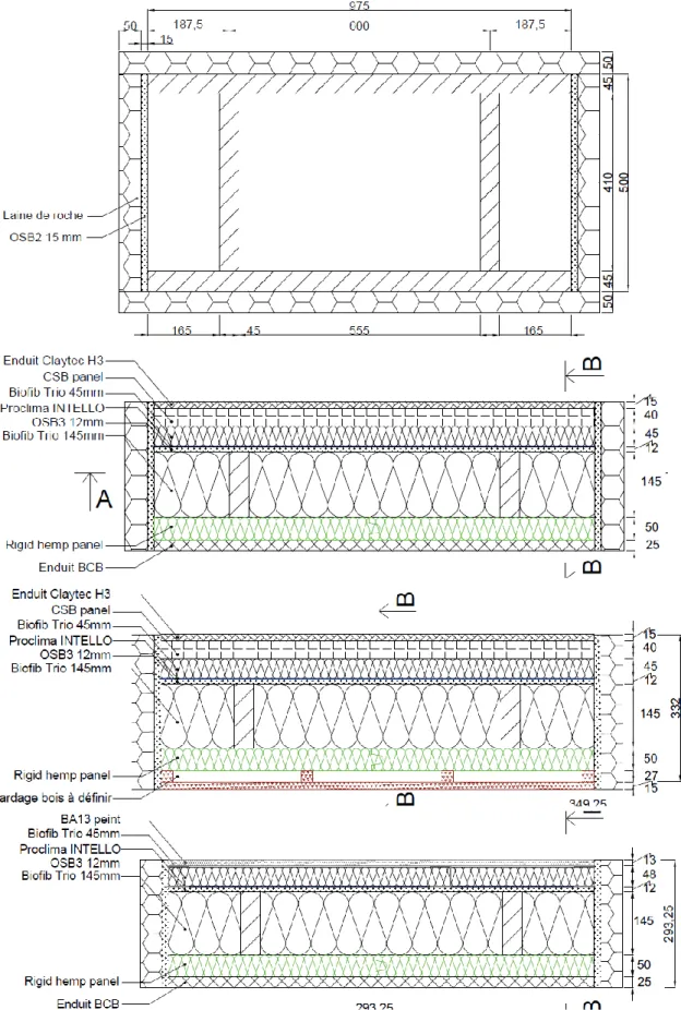
2.1 New building ISOBIO solution
The new building ISOBIO solution wall is made of a wood frame and a commercial oriented strand board (OSB) to ensure the structural stability. a ProclimaTM
INTELLO membrane is applied on the internal face of OSB panel. The wood frame is filled with flexible insulation Biofib Trio panels (hemp-flax-cotton) from CAVACTM. Rigid insulation panels placed on each faces
(compressed straw Lignicell CSBTM panel and rigid
hemp panel from CAVAC) support an external BCBTM
lime-hemp render and a H3 ClaytecTM clay-hemp
plaster.
2.2 Alternative solutions
Two alternative solutions directly derived from the referent solution are developed using traditional finishing materials. One solution consist in the replacement of external render by a traditional wood cladding. The second solution consist in the replacement of internal clay-based plaster by a traditional painted plasterboard BA13.
2.3 Specimen production
The objective of the study is not to evaluate the mechanical stability of the solutions during fire test. Then, the size of the specimen can be reduced to be representative of the wood frame and panel dimensions but must be sufficient to evaluate the multilayer wall performances during the fire test. A compromise is fund with a specimen surface exposed to the fire of 1x0.5 m².
The Fig. 1 present the design of the three tested solutions. The specimens are produced by assembling the wood frame and all the thermal insulation panels. Thermocouples are placed at the same time.
A vertical fire test wall composed of cellular concrete blocks is used to support the specimens. The sealing
between the fire test wall and the specimens is ensured by ceramic wool panels (Fig. 2).
The plaster and render are applied on site. A fiber glass mess ( 5 x 5 mm2 mesh) is used as a reinforcement. A
delay of 28 days for the hardening and drying of the coatings is respected before the fire test.
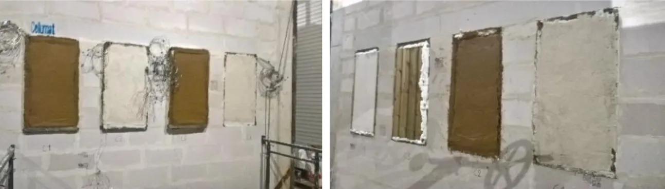
Fig. 2: Specimens placed on the vertical fire test wall: left: unexposed side, right: exposed side
3 FIRE TEST
3.1 Test configuations
The fire test is realized with a vertical gas furnace (CERIB France) of a total power of 6 MW equipped with 12 burners. The furnace open section is 4 x 3 m2 (Fig.
3). The vertical fire test wall is placed in front of the furnace. The fire curve is conform to ISO 834 and test procedure is conform to NF EN 1363-1 [NF EN 1363-1 2013]. The fire temperature is controlled using 16 pyrometers.
Fig. 3: Furnace used for the fire test (CERIB France). Four specimens are placed on the fire test wall to test with the same fire test four configuration C1 to C1:
- C1: ISOBIO referent solution exposed to fire on the external side (outdoor fire).
- C2: ISOBIO referent solution exposed to fire on the internal side (indoor fire).
- C3: alternative solution with external wood cladding exposed to fire on the external side (outdoor fire).
- C4: alternative solution with internal plasterboard exposed to fire on the internal side (indoor fire).
3.2 Recorded data
21 thermocouples are placed into C1 to C3 and 18 thermocouples into C4 to record the heating kinetic. For each specimen, three locations are selected to evaluate the temperature gradient (fig. 4):
- Position A: center of the panel. The 6 or 7 thermocouples are placed at the layers interfaces. - Position B: middle distance between position A and the shorter side of the panel. The 6 or 7 thermocouples are placed at the layers interfaces. - Position C: on the axis of the structural wood stud. The 6 or 7 thermocouples are placed at the layer interfaces.
The thermocouples are noted Tck1 to Tck7. Tck1 corresponds to the first interface behind the fire exposed
layer. The last thermocouple (Tck6 or Tck7) is placed on the unexposed surface of the specimen.
Smoke, cracks and color changes are quoted during the test on the unexposed side.
Fig. 4: Specimens with instrumentation before the fire test.
4 EXPERIMENTAL RESULTS
4.1 Temperature field
The reactions of the specimens to the fire are different. The temperatures on the unexposed side remain low even if the specimen is largely altered in the exposed side. Cracks and color changes are not quoted during the test on the unexposed side. Some change of color is quoted around the specimens on the unexposed side of the wall test. This is due to some problem of sealing between the specimens and the test wall. Smoke release or flame are quoted only when the specimen alteration reaches the unexposed side. The specimens are progressively caulk with a rock wool rigid panel applied on the unexposed side when the flame pass through the specimen (Fig. 5). The test durations are:
- C1 (Outdoor fire on ISOBIO solution): 120 min. - C2 (Indoor fire on ISOBIO solution): 180 min. - C3 (Outdoor fire on wood cladding): 92 min. - C4 (Indoor fire on plasterboard): 65 min.
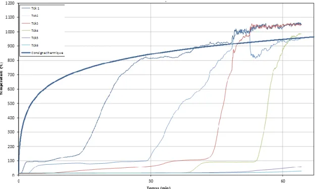
An example of the temperatures curves evolutions versus time is presented in Fig. 6. The furnace temperature set point is the thicker curve. The interface temperatures present quite systematically a temperature plateau at 100°C directly linked to the release of the moisture or bonded water contained in the layer. The comparison of the temperature distributions during test at the different locations (A,B and C) is presented for the specimen C2 in the figure 6. The curves obtained for each interface at the three locations are quite similar. The curve Tck3 (OSB3 panel) leaves the 100°C plateau at 115 min for the location A and at 110 min for the location C (close to the wood frame). The temperature field is then very homogeneous and is quite not altered by the presence of the wood frame. The same conclusions are obtained analyzing the results of C1, C3 and C4 specimens. The temperatures recorded at each interface of the layers of the specimen C2 (Fig. 6) present specific shape with multiple steps. The Tck3 and Tck4 curves correspond to the two side of the OSB3 panel. Each step of Tck1 curve (plaster-CSB panel interface) appears when the temperatures of CSB panel-Biofib trio layer interface then Biofib trio layer – OSB3 panel drastically increases leaving a plateau at 100°C. This plateau is due to the linked water evaporation into each layer. After 3 hours, the temperature at the unexposed side remains lower than 100°C. The temperature quoted at 180 min on the interfaces (Tck2, Tck3 and Tck4) remains lower than 700°C and are stabilized showing that the plaster layer acts as a screen to the heat flux. The end of the test is mostly due to the loose of sealing between the specimen and the test wall and not directly by the destruction of exposed layers.
4.2 Indoor fire
In the cases of indoor fire, the results obtained with the referent solution specimen C2 with clay plastered straw CSB panel presented on Fig 6 can be compared with those of specimen C4 with painted gypsum plaster presented on Fig.7 for the location A. The temperatures curves obtained for C4 present rapid increases until quite 1000°C for all the interfaces. Such temperature level is quite equivalent to the fire curve into the furnace.
Such results suggest a progressive destruction of the layers leading to the shorter test duration. The conventional 15 min duration of plateau behind the layer of plasterboard (Tck1) is quite similar to that quoted behind the plaster in C2 (Tck1 in Fig 6 for position A). The plasterboard loose is stability at 30 min and the other layer are probably exposed to the fire. Destructions of Biofib Trio layer is quoted at 45 min and of OSB3 panel at 60 min. The test is stopped at 65 min due to flame passage through the specimen.
4.3 Outdoor fire
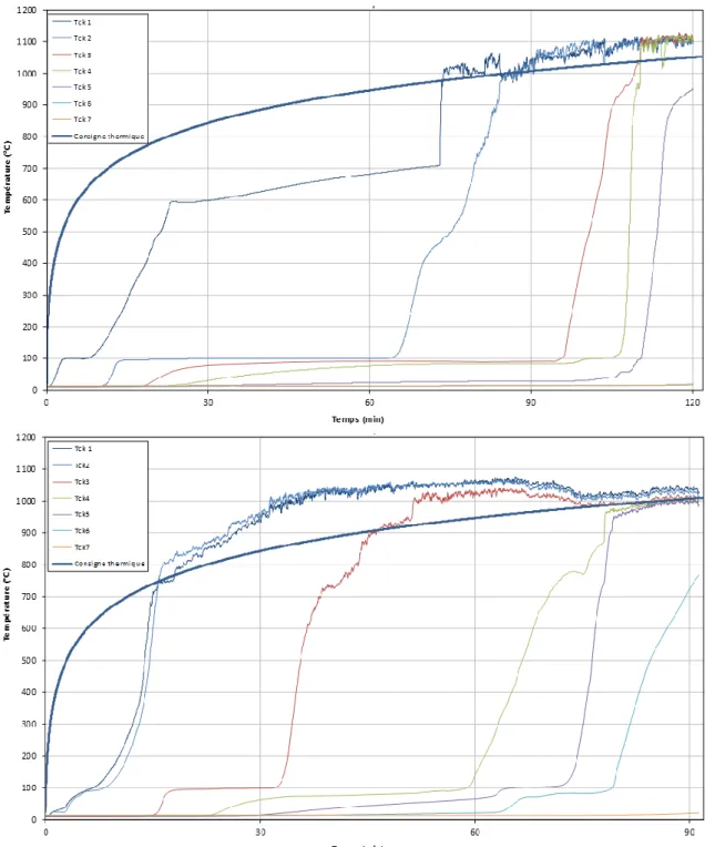
In the cases of outdoor fire, the results obtained with the referent solution specimen C1 with lime-hemp render can be compared with those of specimen C3 with wood cladding. Results are presented on Fig.8 for the location A. In the two cases, the temperatures curves present rapid increases until quite 1000°C for all the interfaces. As mentioned for the study of C4, such results suggest a progressive destruction of the layers. However, the kinetic of the phenomenon is not the same for the two specimens.
In the case of wood cladding exposed to the fire (C3), the increases of temperatures Tck1 and Tck2 appears after only 12 min. The combustion of wood cladding and rigid hemp panel is suspected. The destruction of Biofib Trio layer is quoted at 40 min (Tck3) and OSB3 panel after 75 min (Tck4 and Tck5). The test is stopped at 92 min due to flame passage through the specimen. In the case of ISOBIO Reference (C1), the temperature behind the BCB lime-hemp render (Tck1) is stabilized at around 700°C until 75 min. The Tck1 temperature curve presents a plateau at 100°C with a duration of only 10 min due to low water content of this binder. The plateau at 700°C is perhaps due to the CO2 release linked to the
thermal degradation of the carbonated lime. At 75 min the render probably brakes. The following layer are exposed to the fire. The rigid hemp panel (Tck2) leave the 100°C plateau after 65 min. It destruction is quoted at 85 min. Destructions of Biofib Trio layer (Tck3) is quoted at 110 min and of OSB3 panel (Tck4) at 115 min. The test is stopped at 120 min due to flame passage through the specimen.
Fig. 9: Temperatures versus time at the location A for the specimens C1 (top) and C3 (down).
5 CONCLUSIONS
The data recorded during the fire test on the four configurations give many indications to understand the fire behavior of bio-based building solutions.
The analysis of multilayer specimens degradation during the fire test is full of interest to confirm the design of the proposed building solutions. The fire resistance of such type of bio-based materials multilayer wall can reach 3 hours highlighting the relevance of the solutions. Such type of results is not conventional. The case of wood cladding exposed to the fire leads to a rapid destruction of the wall due to the progressive combustion of the components.
In the case of plasterboard exposed to the fire, the degradation of the gypsum panel induces the start of the wall destruction.
For the referent ISOBIO solution exposed to indoor or outdoor fire, the fire resistance appears directly linked to the integrity of the exposed layer (plaster or render) and to the preservation of the stability of all the constitutive layers.
6 ACKNOWLEDGMENTS
This project has received funding from the European Union’s Horizon 2020 research and innovation program under grant agreement No. 636835 – The authors would like to thank them.
7 REFERENCES
[CEBTP, 2004] CEBTP Grelat, A.; Using sustainable materials as walling for in-dividual housing with wood structure -Final report extracts Volume 2 – Laboratory experiments, Site instrumentation, Update - Convention CEBTP ADEME-ITFFB; July 2004.
[Colson 2017] Colson V.; Le Cunff T.; Jadeau O.; Lanos C.; Industrial scale-up of bio-based insulating panel production. 2nd International Conference on Bio-based Building Materials, Clermont-Ferrand, France, 2017; ISBN: 978-2-35158-192-6.
[CSTB, 2005] CSTB BCB Rapport d’essais RS05-048 Résistance au feu d’un élément de construction: cloison en chanvribloc avec enduit, 2005.
[CSTB, 2009] CSTB Association Bois et Construction Rapport d’essais 26021044 Comportement au feu d’un élément de façade, 2009.
[IBMB, 2014] Institut fur Baustoffe Massivbau und brandschutz TU Braunschweig, Allgemaines bauaufsichtliches prufzeugnis P-3048/817/08-MPA BS, December 2014.
[Intertek, 2007a] Intertek Testing Service; Fire Tests of Building Construction and Materials 2hr fire resistance test of a non loadbearing wheat straw ball wall for Ecological Building Network Project No. 3098054A; July 31, 2006 Revised: July 9, 2007.
[Pavus, 2011] Pavus a.s.; Protokol o zkousce pozarni odolnosti Pr-11-2.097, Nosná stěna z balíků sIámy, september 2011.
[ISO 834 1999] ISO 834. Fire-resistance tests -- Elements of building construction (amd 1-2012). [NF EN 1363-1 2013] NF EN 1363-1. essais de résistance au feu, Partie 1 : exigences générales (march 2013).
[Viel 2017] Viel M.; Collet F.; Lanos C.; Thermal insulation materials from renewable resources: Thermal and hygric performances. 2nd International Conference on Bio-based Building Materials, Clermont-Ferrand, France, 2017; ISBN: 978-2-35158-192-6.