Design and Development of an Automated Three Axis Machine that Prints Images on Top of the Foam of Certain Beverages
By
Jeremy S.H. Richardson
Submitted to the Department of Mechanical Engineering in Partial Fulfillment of the Requirements for the Degree of
Bachelor of Science
at the
Massachusetts Institute of Technology
June 2009
© 2009 Jeremy Richardson All rights reserved
The author hereby grants MIT permission to reproduce and to distribute publicly paper and electronic copies of this thesis document in whole or in part
in any medium known or hereafter created.
Signature of Author . . . Department of Mechanical Engineering May 11, 2009
Certified by . . . David Wallace Associate Professor of Mechanical Engineering Thesis Supervisor
Accepted by . . . John H. Lienhard V Collins Professor of Mechanical Engineering Chairman, Undergrad Thesis Committee
3
Design and Development of an Automated Three Axis Machine that Prints Images on Top of the Foam of Certain Beverages
By
Jeremy S.H. Richardson
Submitted to the Department of Mechanical Engineering on May 11, 2009 in Partial Fulfillment of the Requirements for the Degree of Bachelor of Science in
Mechanical Engineering
Abstract
The goal of this research was to design and develop a working alpha prototype of the flagship product for a local startup called Onlatte, Inc. OnLatte specializes in automated printing of images on top of the foam of beverages such as lattes, cappuccinos, and even certain beers and they have proven the concept with their initial functional prototype. This functional prototype had not been designed with the formal product design process which incorporates customer and market research, feature specification development, and proper physical model
development.
This thesis follows the product design process that led to the development of a working alpha prototype of an automatic latte art printer that was handed off to OnLatte for further development on their way to a production ready product. The main areas of focus for the thesis were to establish proper customer needs and product specifications, and use this information to develop the form factor and the mechanical design of the three axes of movement that were to be incorporated into the machine.
The designer created a series of iterative sketch models and technical models to test different mechanisms and methods of accomplishing the stated functional requirements. At each stage of the process, the pros and cons of each model were assessed and sessions were held to generate new concepts. These new concepts were then used in conjunction with the successful features of the previous concepts to further develop the product until a final alpha prototype that met all of the functional requirements was created.
Thesis Supervisor: David Wallace
5 Acknowledgements
Over the last few years there have been a number of people who have invaluably contributed to my development as an engineer and product designer, and also to my continuous personal growth. I would like to thank Professor David Wallace for providing guidance and insight when needed, yet giving me the freedom to develop the product as I saw fit. A huge thank you goes to Dick Fenner and the Pappalardo crew as well as Mark Belanger and the Edgerton Student Shop. This thesis would not have been completed without the knowledge and resources that everyone there has provided me with throughout these past few months. Thank you John and Tom from the Media Lab shop for letting me use the resources there, and not kicking me out on the numerous occasions where you probably should have. Thank you to Maureen Lynch for helping me to secure funding for the project, and to Professor Blanco for providing the funds.
To Oleksiy and Josh, it has been incredibly fun and exciting working with you during the past few months. I cannot wait to begin working full time on this project. I truly believe that it has potential that we cannot even conceive of at the moment, and I look forwards to working with you both over the next few years to see that potential turn into reality. A brief thanks also goes to Sombit Mishra, the MIT 100K co-lead for 2009. If it wasn’t for your short announcement at the end of our PDD class in early February about the 100K Products and Services track mixer, I would not have gone to it and subsequently met Josh, which is where my affiliation with OnLatte began. I also want to thank Matt Kressy for your help early on in the project, and also for any future guidance you provide me with.
I want to thank Brian Shimon, my high school guidance counselor. The help and mentorship you provided me with during my MIT application process was invaluable, and I seriously do not know if I would be here at all without it. Last, but certainly not least, I want to thank my parents. Thank you for being nurturing and attentive during the early stages of my life, quickly recognizing and cultivating my passion for design. Thank you for giving me the independence that I needed when growing up and allowing me to make my own decisions along the way. Finally, thank you for all of the sacrifices that you have made for Tia, BJ, and myself; we all deeply appreciate everything that you have done for us, and I cannot wait until the day that I am able to give back to you.
7 Table of Contents Abstract . . . 3 Acknowledgements . . . 5 Table of Contents . . . 7 List of Figures . . . 10 List of Tables . . . 11 1. Introduction . . . 13 1.1. Objective . . . 13 1.2. Outcome . . . 13 2. Background . . . 15
2.1. Origins of the Latte Art Printer . . . 15
2.2. The Original Prototype . . . 15
2.3. OnLatte, Inc . . . 16
3. Market Research . . . 18
3.1. State of the Art . . . 18
3.2. Coffee Shop Interviews . . . 19
3.2.1. Reactions to the Product . . . 20
3.2.2. Details of a Coffee Shop . . . 20
3.2.2.1. The Physical Environment . . . 20
3.2.2.2. Cups and Lids . . . 21
3.2.3. Pricing a Latte Art Printer . . . 22
3.3. Critical Customer Needs . . . 22
3.4. Target Specifications . . . 24
4. Concept Development . . . 26
4.1. Sketch Models . . . 26
4.1.1. Closed Entry Way . . . 26
4.1.2. Open Entry Way . . . 28
8
4.1.3.1. Results of the Case Study . . . 31
4.2. Technical Model . . . 34
4.2.1. Y Axis Drive Mechanism . . . 34
4.2.1.1. Threaded Rod . . . 34
4.2.1.2. Rack and Pinion . . . 35
4.2.1.3. Timing Belt . . . 35
4.2.2. Z Axis Drive Mechanism . . . 35
4.2.3. X Axis Drive Mechanism . . . 36
4.2.4. Physical Model . . . 36
4.3. Final Design . . . 37
4.3.1. Overview . . . 37
4.3.2. Y Axis Carrier . . . 38
4.3.2.1. Carriage Physical Design . . . 38
4.3.2.1.1. Printing Envelope . . . 38
4.3.2.1.2. Cup Clearance . . . 40
4.3.2.2. Drive Mechanism . . . 41
4.3.2.2.1. Motor Calculations . . . 41
4.3.2.2.2. Motor Selection and Drive Train . . . 41
4.3.2.3. Raised Front Bridge . . . 43
4.3.3. X axis Carrier . . . 44
4.3.3.1. Carriage Physical Constraints . . . 44
4.3.3.2. Drive Mechanism . . . 46
4.3.3.2.1. Motor Calculations . . . 46
4.3.3.2.2. Motor Selection and Drive Train . . . 46
4.3.4. Z Axis and Frame . . . 48
4.3.4.1. Frame Physical Constrains . . . 48
4.3.4.2. Drive Mechanism . . . 49
4.3.4.2.1. Motor Calculations . . . 49
9 4.4. Industrial Design . . . 50 4.4.1. Conceptual Sketches . . . 50 5. Conclusions . . . 52 5.1. Summary . . . 52 5.2. Future Work . . . 52 References . . . 54 Appendix A . . . 55 A.1 . . . 55 A.2 . . . 56 A.3 . . . 57
10 List of Figures
Figure 1-1: Final Thesis Design for the Latte Art Printer . . . 14
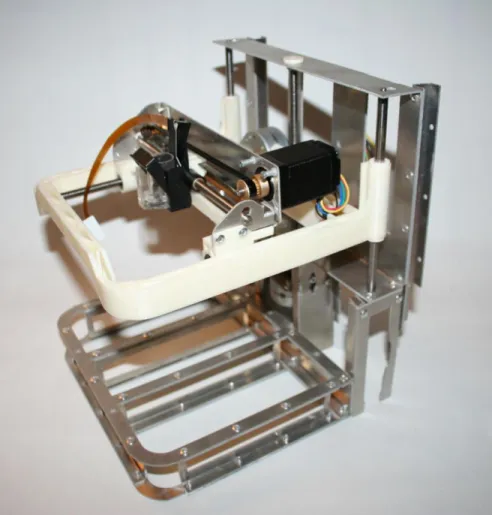
Figure 2-1: The First Functional Prototype of the Latte Art Printer . . . 16
Figure 2-2: An Actual Printing on the Foam of a Latte from the First Printer . . . 16
Figure 3-1: A picture of the MX-315 Chocolate Printer . . . 17
Figure 3-2: Envelopes of the Height and Diameters of the Documented Cups . . . 21
Figure 4-1: Sketch Model One . . . 27
Figure 4-2: Sketch Model Two . . . 28
Figure 4-3: Insert Number One Consisting of Two Concentric Cutouts . . . 30
Figure 4-4: Insert Number Two with Three Levels of Concentric Cutouts . . . 30
Figure 4-5: Insert Number Three with Three Raised Concentric Rings . . . 31
Figure 4-6: A Slanted Cup Resulted from Falling into Insert Three . . . 32
Figure 4-7: Shows an Eccentric Cup in Insert Three . . . 33
Figure 4-8: The Technical Model Used to Test the Y and Z Axes . . . 36
Figure 4-9: A Finished CAD Model of the Y Axis Carrier . . . 38
Figure 4-10: Diagram of the Sketch Made to Determine the Printing Envelope . . . 39
Figure 4-11: Sketch Made to Determine the Needed Clearance for the Y Carriage . . . 40
Figure 4-12: Labeled Assembly of the Y Axis Carriage . . . 42
Figure 4-13: The Raised Front Bridge and How Much it Decreases the Overall Height by . . . . 43
Figure 4-14: An Image of the Final X-Carrier CAD Assembly . . . 44
Figure 4-15: The Height of the Print Head Surface Relative to the Carriage Bottom Surface . 45 Figure 4-16: Side view of the X Carrier and Y Carrier, Showing the Vertical Gap of Overlap . . 45
Figure 4-17: Fully Assembled X Carrier with Stepper Motor and Timing Belt Installed . . . 46
Figure 4-18: CAD Model of the Idle Pulley and Linear Tensioner . . . 47
Figure 4-19: CAD model of the Print Head Timing Belt Connector . . . 47
Figure 4-20: CAD Model of the Completed Z Axis and Frame Assembly . . . 48
Figure 4-21: Shows the Force Traveling Through the Thrust Bearing, Down the Frame . . . 49
Figure 4-22: Hand Drawn Sketches of Possible Aesthetic Designs . . . 50
11 List of Tables
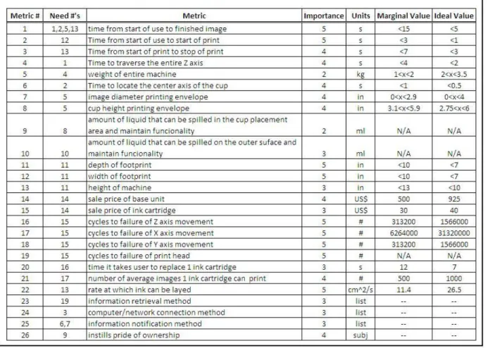
Table 3-1: The Final Customer Needs for the Latte Art Printer . . . 24 Table 3-2: The Final Product Specifications for the Latte Art Printer . . . 25
13
Chapter 1
Introduction
1.1. Objective
The goal of this research was to use the product design process to develop a prototype of a latte art printing machine for a local startup called OnLatte, Inc (website: onlatte.com). The prototype was to be developed with specific design constraints based on customer research gathered during the early stages of the process. After these constraints were identified, several sketch models were then made in order to get a general feel of the product architecture. After the necessary information was gathered from the sketch models, a technical model was
designed to gather further information about certain functionality in question. The final step in the process was to use all of the learned information to design a final functional prototype that would be the basis for further design prototypes until a production worthy product is created. The developed product was required to use a pre-existing ink cartridge supplied from an outside company, and have a form factor similar to that of a production ready product for the startup to take and develop further, but it was not necessary for this prototype to account for or use mass-production processes into its fabrication or design.
1.2. Outcome
After a long period of customer research, specific primary customer needs were
developed. From these needs, a list of detailed product specifications was defined on which to base the final product functionality. The product specifications that were developed during the market research phase of this thesis were almost comprehensive enough to cover all of the main areas of a production ready product. However, only the primary functional needs were taken into account for this thesis design, all of which were met, leaving the other needs to be accounted for in future iterations of this product.
14
15
Chapter 2
Background
2.1. Origins of the Latte Art Printer
In the summer of 2008, Oleksiy Pikalo was watching a show on television about barista latte art. In this art, a skilled barista uses hand held tools to make various pictures in the foam of a latte. While watching, he had the idea of making a machine that could do this, but with much more accuracy and repeatability. Within a few weeks he had a working machine, capable of printing any image on top of any drink that has foam on its surface.
2.2. The Original Prototype
The first machine that Oleksiy invented was a combined scanner and printer. The scanner served as the base of the machine as well as its Y axis, using the existing stepper motor and timing belt for this application. The print head served as the X axis, and this was mounted at the end of the scanner’s Y axis. Together, the 2 axes allowed the machine to print over the entire surface of a cup, but it did not allow for variable cup heights. This first prototype was perfect for a proof of concept, but was not designed with the product development process in mind and thus not fit to convey the intent for a final product.
16
Figure 2-1: The First Functional Prototype of the Latte Art Printer
Figure 2-2: An Actual Printing on the Foam of a Latte from the First Printer
2.3. OnLatte, Inc
After he invented the first machine and both domestic and international patents had been filed, Oleksiy put a few videos of it on youtube.com. Within a few days, the videos got hundreds of thousands of hits. People eventually began to ask where they could purchase such a
17
machine, and that is when he realized that this machine actually had market potential. It was after this realization that he founded OnLatte, Inc, along with his co-founder Josh Grob who serves as the Director of Products and Services. During its first few months, OnLatte made revenue doing small promotional events for various organizations with their first prototype, but they had not yet pursued mainstream production of this product. The prototype developed from this thesis will be the first step towards a production product ready to be sold to the masses. For more information about OnLatte, please visit onlatte.com.
18
Chapter 3
Market Research
3.1. State of the Art
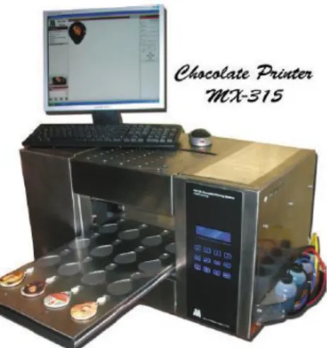
While the concept of printing directly on top of a foamy beverage is novel, the idea of printing on top of food in general is long standing. There are many different companies that produce printers that have the ability to print edible ink on top of cakes, cookies, lollipops, and other candies, but none that print on top of beverages. Therefore, the closest comparison products would be food printers that are designed to automatically accommodate a wide variety of size and height difference in the food that it prints on. One existing product that fits into this category is the MX-315 “Chocolate Printer” manufactured by MasterPiece Systems Co. Ltd [1].
Figure 3-1: A picture of the MX-315 Chocolate Printer
In the text Product Design and Development [2], by Ulrich and Eppinger , there are four types of product development projects defined:
19
- New product platforms: This involves creating a new family of products based on a new, common platform, but would address familiar markets and product categories.
- Derivatives of existing product platforms: This extends an existing product platform to better address familiar markets with one or more new products
- Incremental improvements to existing products: This only involves adding or modifying some features of existing products in order to keep the product line current and competitive. - Fundamentally new products: This involves radically different product or production technologies and may help address new and unfamiliar markets, usually involving high risk.
While, on a conceptual level, the MX-315 above is very similar to the latte art printer developed in this thesis, there are a few fundamental attributes of this product that would not be
acceptable in the latte art printer. The size and weight are far too large, and the user interface is more complicated than was acceptable in the latte art printer. Also, the market for printing on food is developed, while the market for printing on beverages was new and untapped. Thus, the latte art printer fell into two of the above four categories. It was partly an incremental improvement to an existing line of products, standard cake and chocolate printers, but there were also fundamentally new aspects of it, primarily the strict constraints for its size and also the fact that it was the first product to approach the foamy beverage market.
3.2. Coffee Shop Interviews
Since this was a first to market product, there was no customer data available on which to develop product specifications with. Because of this, detailed customer research had to be conducted to help determine the right specifications this product needed to have. The
projected initial target market for this product was to be coffee shops, so this was primarily where the research took place. The managers of nine local coffee shops were interviewed in person and asked specific questions about their thoughts about a product like this in a coffee shop, the physical layout and logistics of their shop on a daily basis, and the economics of using this product.
20 3.2.1. Reactions to the Product
The only prototype available at the time of each interview was the first one developed by Oleksiy. It was not possible to carry it around to each coffee shop, so each interview began with the manager watching a short video of a latte being printed on with this prototype. In general, there were two distinct reactions to the idea of automatic printing on top of a latte: excitement or repulsion.
Coffee shop managers had two different mindsets towards latte art. The first, which was a more traditional viewpoint, valued the hard work that it takes to learn the skill of barista latte art. These thinkers initially do not see value in this type of product because they think it
detracts from what is most important in a latte, the taste, and so they were not enthusiastic about this product. The second type of thinker was more open minded to new ideas when it came to coffee shop business, and they immediately saw the value in a product like this for a coffee shop. These types of thinkers are generally early adopters to new products, and define the initial market for this product. Five of the nine managers that were interviewed fall into this latter category, and were excited about this product.
3.2.2. Details of a Coffee Shop 3.2.2.1. The Physical Environment
From a customer standpoint, the ambiance and general feel of most coffee shops is always very warm and comforting. Behind the counter, however, this was not the case. The various machines took up most of the counter space, leaving very little room to work on or add more machinery. The baristas were almost constantly multitasking, making drinks while
processing orders, and oftentimes making sandwiches as well. The combination of the very little open space and the fast movements results in a very high probability of beverage
splashing and spillage, making the environment rather messy as well. All of these factors were important and needed to be addressed in the final design.
21 3.2.2.2. Cups and Lids
The cups that coffee shops use vary widely in shape and size. While a majority of the cups sold are standard cardboard sizes, many coffee shops still use ceramic and glass mugs for the customers who sit in the shop. In order to get a comprehensive database of cup sizes that needed to be accounted for in the machine, the critical dimensions of each cup at every
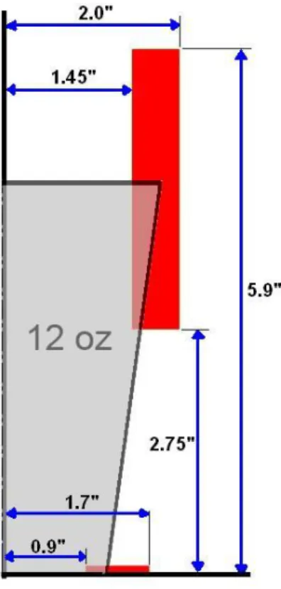
location were measured and recorded. Figure 3-2 shows, in red, the envelopes that encompass the height, upper lip radius, and bottom ring radiu of each cup that was documented. The half-cross section of a 12 ounce cup is shown for reference.
Figure 3-2: Shows the Envelopes in Red of the Height and Diameters of the Documented Cups
One important detail that was realized after the cup lip diameters were shown in aggregate was that the maximum and minimum only differ by about one inch, with the maximum being four inches. While this may initially seem like a big difference, radially this is only 0.5 inches. In this case, the radius was important than the diameter because in order to
22
discern the difference in size of two concentric circles, we tend to look only at the distance between the outer circle and the inner circle: the difference in radii. Because of this, it was decided that it would be acceptable to only print one image size of about 3 inches. This size is small enough to fit inside the smallest cup diameter, and will fit comfortably within the average cup sizes: the 12, 16, and 20 ounce cardboard cups.
Another question that was addressed during the interviews is that of the coffee lid. Obviously, if a latte had a lid on it then it would render this product useless. While this could be a concern, about half of the coffee shops already handed the customers their drinks with the lid off so they can put condiments into it. They simply had the lids at the condiment table for the customer to put on when ready. Of the shops that do hand out drinks with lids on them, they were all fine with changing their routine and letting the customer put their own lids on if they were to use this product.
3.2.3. Pricing a Latte Art Printer
While it is very hard to incorporate the expected sale price of a product this early into its design, we thought it would be a good idea to get an idea of how much a potential customer would expect to pay for this product. The machines that coffee shops purchase can cost
anywhere between $500 and $10,000. When asked how much they would expect to pay for this product, the responses were between $300 on the low end and $1500 on the high end. Of the responses, the average expected price from the five managers that were excited about the product was about $900.
3.3. Critical Customer Needs
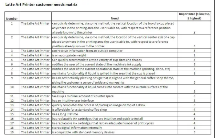
Upon completion of the interviews and compilation of all of the gathered data, a set of critical customer needs was developed. Of the entire set of needs, there were a few that were critical to the success of the product.
The most important general need that had to be met was the speed of the printer. The average response for time of print from the managers was five to ten seconds. This was very important because during peak times a coffee shop can hand out drinks as frequently as once
23
every 30 seconds. If the processing time of the printer was too long, then it would drastically affect the overall performance of the shop.
Another important area that had to be adequate was the form factor. As previously stated, there is very little counter space in most coffee shops. The footprint of the latte art printer had to be small enough such that very little effort needed to be made to make it fit onto existing countertop space. It also needed to be able to accommodate a wide variety of cups in order to be more universal.
The third critical area was the need for a very quick and simple user interface. Baristas constantly multitask and, while they are capable of learning how to use moderately
complicated equipment, they ideally should not have to learn how to use this product. It is ok for them to need to be trained how to properly use a $5000 espresso machine because that is vital to a coffee shop’s survival. However, a secondary machine such as the latte art printer isn’t perceived to be as important to a shop, so there could not be any aspects from a user
standpoint that detract from the value of the machine.
When asked how many images they would like the machine to store at once, every manager replied with the same answer: one. When envisioning use of the product, they would only put an image onto the printer in the morning before they opened. They would not have time, nor did they see the need, to change the picture during operating hours. This allows the machine interface to be very simple, only having to store 1 image at a time, meaning there is no need for multiple buttons that the user had to interact with. Table 3-1 shows the final customer needs that were established after the coffee shop intereviews.
24
Table 3-1: The Final Customer Needs for the Latte Art Printer
3.4. Target Specifications
From the finalized customer needs, a more detailed list of product specifications was made. Unlike customer needs, which are supposed to be both vague and loosely defined, product specifications are meant to define more clearly a standard that each area of function in the product needs to have. Each specification was given an ideal and marginal numerical value. The marginal value is meant to be the worst performance allowable with which the product would still sell.
For the speed of printing, there were many different sequences that can happen within the product in order to print a cup. While each of these steps needed to be independently defined and addressed an ideal and marginal value, the overall speed of printing is what is most important. From the customer research, it was determined that a ideal value for time from start of usage to end of usage is 5 seconds, with a marginal value being 15 seconds.
25
The ideal value for the footprint of the machine was chosen to be 7 by 7 inches. As previously stated, it will print one image size of about three inches, and will be able to
accommodate cups with diameters as large as four inches. The ideal maximum height it will be able to print on is 6 inches, with the lowest being 2.75 inches.
26
Chapter 4
Concept Development
The customer needs and product specifications that were generated from the market research defined a majority of the functional needs, but they intentionally did not go into actual design detail. After the initial research steps were taken, the actual mechanical design
development of the product took place. This process began with brainstorming of various concepts that had potential to solve the functional requirements previously stated. After the initial brainstorming sessions, sketch models were created which enabled the designer to get a physical feel of the form factor and conduct preliminary user interaction tests with the model. After enough information was discovered from the sketch models, the designer then further developed the mechanical design by creating technical models. These models were more detailed than the sketch model, and the purpose was to get a better understanding of a specific module within the design. After the fabrication and testing of the technical model was done, enough information was known to begin the final detailed design of the prototype that would fulfill all of the requirements stated in the beginning of this thesis.
4.1. Sketch Models
There were three sketch models made during this stage of the design process. The purpose of the first two was to get a better feel of the necessary form factor constraints that needed to be placed on the final product. The third sketch model was more of a case study to determine the best method for the user to place a cup inside of the machine.
4.1.1. Closed Entry Way
The first sketch model was a cardboard mockup made to get a general feel for the user interaction of this particular form. It was comprised of two main sections: the cup placement area and the rest of the body. The size of the body was made to be within the ideal
27
specifications for the footprint and the height. However, the size of the cup placement area was not defined in the product specifications because there was no existing product that could be compared to this part of the design.
To determine what the best form factor for the cup placement area would be, this sketch model started out with a box that was capable of fitting both the largest cup height and printing diameter, with some tolerance built in as well. The front face of this box was cut out, allowing the user to place the cup in and out. To test the model out, about 10 different people were instructed to place three cups full of water of different sizes into the cup placement area. The overall ease of use and technique was closely monitored as each participant placed each cup down.
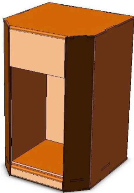
Figure 4-1: Sketch Model One
This model proved to be very useful in determining the proper design of the cup placement area. It quickly became clear that the box with only the front face open was far too crowded when the user tried to place a full cup of water inside the model. The people with larger hands had to orient their hands in various ways and it became very awkward and uncomfortable. In order to solve this problem, another sketch model needed to be created.
28 4.1.2. Open Entry Way
The second sketch model used the same body as the first, except the cup placement area was much more open. The width of the area was changed to be the entire width of the machine, essentially eliminating the cup placement box walls altogether. This allowed the user to comfortably place a full cup into the placement area.
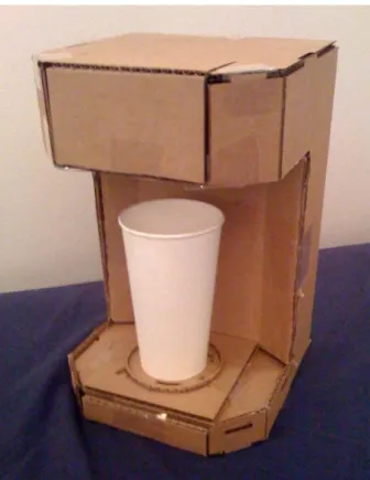
Figure 4-2: Sketch Model Two
This new form factor constraint drastically affected the design requirements of the Z axis. Because the entire area below the Y axis carriage that travels up and down had to be open to allow the user to place the cup down freely, all of the components of the Z axis had to be pushed to the back of the machine. This was not ideal because it eliminated the opportunity to design the Z axis with symmetry, which would have reduced any torque applied to the shafts that would support the Y axis carriage.
29 4.1.3. Cup Placement Study
The purpose of the third sketch model was to determine if it was possible to ensure the proper alignment of the cup when it was placed into the machine without the use of
electronics. This need arose when the idea was brought up to locate the cup via a set of three infrared sensors that would triangulate the position of the cup’s central axis. While the complexity of this design is well within the technical competency of the design team, it would have been much easier to simply create a physical passive way to make sure that the cup is always in the center of the machine. This way, the machine would never have to actually locate the cup position and can print in the same place time after time.
In order to come up with a way to passively get the center of the cup into the same location every time, three different inserts were created. These inserts were used in
conjunction with the above sketch models to test their effectiveness. Much like the method used to test the cup placement area; there were about ten different users who were instructed to place full cups into the sketch model with each insert. After each cup placement, the
magnitude of the error was noted for each insert.
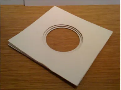
The first insert was simply a flat square piece of cardboard with two concentric circles cut out of it. The idea behind this design was to see if users were able to accurately place a cup down only using the visual cues from the concentric rings. If this was possible, then the need for a physical aid in placing the cup down would be eliminated, reducing the complexity and cost of the final product even further.
30
Figure 4-3: Insert Number One Consisting of Two Concentric Cutouts
The second was a stack of three square pieces of cardboard. Each square had a circle cut out in the middle. The bottom square had the smallest circle, with the diameter of the circle in the middle square larger, and the top square the largest.
Figure 4-4: Insert Number Two with Three Levels of Concentric Cutouts
The third insert was a square with a set of three raised concentric rings. The diameter of the inside ring was designed to fit inside of the bottom of the smallest recorded cup measured
31
during the market research phase of the design process. The middle ring was large enough to fit the bottom ring of the top three most used cardboard cups, and the largest ring was designed to fit the bottom ring of the largest ceramic mug that was measured.
Figure 4-5: Insert Number Three with Three Raised Concentric Rings
4.1.3.1. Results of the Case Study
While it is less complex than any other method, the first insert proved that a visual cue alone is not enough to ensure proper cup placement by a user without having to make a significant conscious effort to make sure the cup is concentric with the rings.
The second insert proved to be much more conducive to easy center placement of the cup. The fact that there was a hole in the square that the user could see meant that they consciously would place the cup there. However, a major problem that often occurred was that the cup would fall into the hole if it were misaligned enough. In an attempt to solve this
problem, another insert was made with pieces of cardboard with wall thicknesses that were three times less than the original. While it helped, the problem persisted and this insert was ruled out as well.
32
Figure 4-6: A Slanted Cup Resulted from Falling into Insert Three
After the tests, the third insert showed promise. The rings did not make the cups tilt, and it was fairly easy for each user to place the cups inside of the rings. The main drawback of this design was that there was an inherent tolerance in the design that allowed for cup
misalignment within the rings. Even if a cup were placed inside a ring, it could still slide until it hits either the wall of the inner ring or the wall of the outer ring surrounding it. The distance that the cup was off by is based on the gap distance between the rings, which has to be large enough to fit a certain number of cups inside. If the gap is too small then it will essentially function as the first insert because the bottom lip of the cup will ride on top of the ring and not fall into place. After some thought, this design was ruled out as well.
33
Figure 4-7: Shows an Eccentric Cup in Insert Three
At the conclusion of this case study, it was decided that the final product will use the infrared sensors to locate the central axis of the cup. This will greatly improve the robustness and quality of the end result that the customer will see. In the fast paced coffee shop
environment, it is inevitable that the user will place the cup into the machine with little regard for its position. The machine will be much more robust to cup eccentricity if it is able to actively locate and print over the cup, and the end result will be of higher quality as well because the picture will always be concentric with the cup itself.
34 4.2. Technical Model
With the acquired information from the sketch models and case study, there was enough known to start the more detailed design of the prototype. To start this process, a brainstorm was held to come up with ways to create the more technically complicated parts of the machine: the X, Y, and Z axes.
4.2.1. Y Axis Drive Mechanism Selection
The Y axis and its carrier was the first part of the machine to be considered. This part of the machine is what traverses the Z axis vertically, and it also is what the X axis mounts to and translates on. It can be looked at as the heart of the entire machine, and the way it was going to be designed would have a large impact on the other modules in the machine.
During the beginning stages of the conceptualization of this axis, there were a few design constraints put into place based primarily on the customer research. The main constraints were that it would need to accommodate approximately 4 to 5 inches of travel in the X axis, the Y axis drive needed to have a linear translation accuracy on the order of 0.05 millimeters, and that it needed to be capable of fast, high impulse starting and stopping of the X axis carrier with no backlash or distortion.
4.2.1.1. Threaded rod
The first idea was to use a threaded rod to drive this axis. The main pros of this concept were that it was precise, was cheap with a low part count, had little backlash, and it had the ability to rapidly start and stop. Another pro to this idea iwas that there were certain threaded rods with very high leads. These rods have an especially high pitch, some of which provide as much as an inch of linear movement with one rotation. This is ideal because it would ensure that the X carriage could translate fast enough in order to meet the ideal process time defined in the product specifications.
35 4.2.1.2. Rack and Pinion
The second idea was to use a rack and pinion to drive the Y axis. The main pro of this idea was that it would be very fast, which was a high priority. However, the facts that a rack and pinion would be prone to backlash and that the alignment between the two parts is critical proved to be a rather large con in this design.
4.2.1.3. Timing belt
The third idea was to use a timing belt. This idea initially had high potential because of its fast nature and ability to start and stop quickly. However, the part count required for this design, given that it would need a tensioner, was a drawback. Also, unlike the threaded rod which can serve as both a support shaft and a drive shaft, a timing belt would need support shafts for the X carrier to slide on while it drove it. This was another area that increased the part count.
In the end, the threaded rod was chosen as the concept to move forwards with for the physical technical proof of concept that was to be made.
4.2.2. Z Axis Drive Mechanism
The same process that was used to determine the Y axis proof of concept model was used for the Z axis. The primary design constraints for this axis were that it needed to be capable of traveling about 4 inches vertically in 1 to 3 seconds. It had to have an accuracy of about 2 millimeters, and needed to be able to reach these goals while lifting a load of one to two pounds. One final constraint that is important for the Z axis is that the drive mechanism is not back-drivable, so the Y carrier will translate down when the motor is not running.
The same three linear translation mechanisms that were weighed in the Y axis
brainstorm were used for the Z axis. The threaded rod again proved to be the option with the best outlook, primarily because of its ability to maintain the vertical position of the Y carrier while the motor is without power.
36 4.2.3. X axis drive mechanism
While there are many ways to drive the print-head which rides along the X axis, most modern printers use the timing belt method. This is a very fast way to translate a low weight object like a print head. In order to get the same performance with a threaded rod, it would have to continuously spin at high angular speeds which would create a lot of friction and cause the mechanism to wear down relatively quickly. The concern with the rack and pinion was that in standard designs the pinion moves relative to the stationary rack. If this were the case, then the motor would also have to move with the print head. Because of its added inertia and
weight, the motor would have to work extra hard and need to be larger. It was decided that the timing belt option was most ideal for this very lightweight high speed application.
4.2.4. Physical Model
Upon completion of the three axes brainstorm, a physical technical model was created. The purpose of the model was to test the performance of the Y and Z axes. The X axis was left out because it has been proven for this application in various existing products.
37
The Y axis design for this physical model was a standard two shaft design, one of which was the threaded rod. Because of certain design constraints with the X carrier, the ratio of width to bearing length for the X carrier riding on the Y axis was less than ideal. When attempting to drive the X carrier along the Y axis by spinning the threaded rod, it would bind because of the poor ratio. In order to solve this problem, it was decided that both shafts of the Y axis should be threaded rods, and they would be connected with a timing belt, driven by a motor.
The Z axis, however, worked seamlessly. The threaded rod was in the middle of the two shafts, creating a nice symmetric load distribution. Also, the Y carrier slider bearings that traveled along the X axis shafts were long enough to prevent binding from the torque created by the asymmetric location of the Z axis.
With the information gathered from this physical technical model, the final functional design was ready to be created.
4.3. Final Design 4.3.1. Overview
With all of the customer needs and product specifications, as well as the gained knowledge from the sketch and technical models in mind, the final functional prototype was designed. It was separated into three main modules: Y axis carrier, X axis carrier, and the Z axis and frame. The Y axis carrier was designed first, followed by the X axis carrier, and finally the Z axis with the frame. After assembly of all modules was complete, further design iterations took place to ensure that the design interactions between modules were adequate.
38 4.3.2. Y axis carrier
Figure 4-9: A Finished CAD Model of the Y Axis Carrier
4.3.2.1. Carriage physical design 4.3.2.1.1. Printing envelope
This was the first module designed because it directly involved incorporating the printing envelope that the machine would be capable of. This printing envelope played the largest role in determining the overall footprint of the machine. To begin the process of
determining the smallest possible size that the carriage could be, a sketch was drawn to visually see just how large the print envelope had to be. To do this, first a 3.5 inch diameter circle was drawn, shown in green in Figure 4-10. This was to represent the area in which a cup can be placed into the machine by the user. In the final design, an indentation of a 3.5 inch diameter circle was to be placed on the cup placement surface, showing a clear visual and physical indication of where to set the cup. Next, shown in blue in Figure 4-10, a 2.5 inch circle was drawn inside of the 3.5 inch circle, with its circumference tangent to the 3.5 inch circle. This 2.5 inch circle represented the smallest measured bottom lip diameter cup, as if it were placed with
39
the largest possible deviation from the center of the 3.5 inch circle. Next, shown in red in Figure 4-10, a 3 inch circle was drawn concentric to this offset 2.5 inch circle. This 3 inch circle
represents the actual image that would be printed onto the cup in this location, the size of which was determined in the above section 3.2.2.2. Next, shown in black in Figure 4-10, a circle was drawn concentric to the original 3.5 inch circle, but tangent to the offset 3 inch red circle. This largest circle represents the entire possible area that is required to be covered by the print head. To better understand this, imagine taking the cup that is offset and tangent to the outer edge of the green 3.5 inch indentation and rotating it around the entire circumference of the 3.5 inch circle, maintaining tangency between its bottom diameter, the blue circle, and the green circle. That area is what the largest circle is encompassing.
40 4.3.2.1.2. Cup Clearance
The second step in defining the size of the Y carriage was to ensure that the carriage had enough clearance so that it would not hit a cup when it lowers. In this design, the bottom surface of the print head is higher than the bottom face of the Y carriage. This means that when it lowers, the bottom face of the carriage will actually be lower than the top surface of the cup that it is printing on.
Figure 4-11: Diagram of the Sketch Made to Determine the Needed Clearance for the Y Carriage
To design the carriage for this clearance a similar sketch to the one for the printing envelope was made, illustrated in Figure 4-11. The green circle again represents the 3.5 inch indentation for the cup placement. The offset tangent blue circle represents the bottom
diameter of the cup if it were in the largest possible deviation from center of the cup placement area. This time, shown as orange in Figure 4-11, a 4 inch circle was drawn concentric to the blue 2.5 inch circle. This represents the largest top lip diameter measured from the market research.
41
The next step was to create a circle that was concentric to the initial 3.5 inch circle and tangent to this new 4 inch circle, shown in black in figure 4-11. This new largest circle represented the entire envelope where the top lip of a cup could be located.
From this, two rectangles were drawn to represent the two threaded rods that would serve as the Y axis, shown in brown in Figure 4-11. Around each of these rods was drawn another rectangle to represent the bushing that would travel across each threaded rod, shown in tan in Figure 4-11. The inside edge of each of these tan rectangles was dimensioned to be 0.01 inches from the large black circle from Figure 4-11. These three steps were crucial in determining the overall size of the Y carriage, which largely affected the overall size of the entire machine.
4.3.2.2. Drive mechanism 4.3.2.2.1. Motor calculations
Before a motor was decided upon, calculations were done to figure out the required stall torque that was needed. The method used to determine this incorporated the diameter and lead of the threaded rod, the print swath size of the print head which is how wide the path is that is created from one print pass, the time required to travel one step in the Y axis
direction, and finally the X axis carriage weight. It was found that the stall torque required to fulfill the necessary requirements was about 0.1 ounce-inches. This, however, did not include any friction forces which are very abundant in this system. Because it would have been difficult to predict the frictional forces that would come up, it was decided that the motor to be chosen should have at least 10 times the calculated required stall torque. See Appendix A.1 for details of the calculations.
4.3.2.2.2. Motor selection and drive train
It was decided that the best option of motor selection for the Y axis would be to use a stepper motor. This would provide the ability to locate the position of the X carriage without any added components, and stepper motors are an economical option for the torque range required for this design. The stepper motor that was chosen was rated as having a 15.1
ounce-42
inch holding torque, and a 7.5 degree step angle. This precision was well within what was required: with the threaded rod that was used for the Y axis, the motor would have to turn 0.5 revolutions, 24 steps, per X carriage movement step.
The drive train to run the two threaded rods simultaneously consisted of a timing belt and multiple pulleys to keep it properly tensioned. The motor was placed in between the Z axis threaded rod and the left Z axis shaft that the Y carriage slides along. It was necessary to place the motor within the footprint of the Y carrier because if it were to extend beyond either side or the front then it would interfere with the walls of the machine.
43 4.3.2.3. Raised front bridge
The front bridge of the Y carrier is raised to prevent the carrier from interfering with the cup as a user places it into the machine. It also reduces the height that the Y carrier has to be when in its highest position. If the bridge were not raised, then the entire carrier would have to be higher by its vertical thickness in order for the bottom surface of a straight front bridge to be at the same height as that of the raised front bridge. It is simply more efficient to have the front bridge lower, and allows for the overall machine height to be lower as well.
44 4.3.3. X axis carrier
Figure 4-14: An Image of the Final X-Carrier CAD Assembly
4.3.3.1. Carriage physical constraints
A majority of the physical constraints applied to the X carriage design were a result of the Y carriage size. The width of the axis is directly related to the Y axis, and the other outer dimensions are defined so they do not interfere with the Y carriage.
There is one constraint that is brought on by the print head. There cannot be any
surface lower than the bottom face of the print head within the two threaded rod shafts. This is so, when lowered to cup level, the carriage body does not interfere with the foam on the cup.
45
Figure 4-15: Shows the Height of the Print Head Surface Relative to the Carriage Bottom Surface
The part of the X carriage that actually contacts the Y axis is as short as possible. This minimizes the length needed for the Y axis threaded rod, which minimizes the entire length of the machine. In order to make this as efficient as possible, most of the X carriage actually rides above the top surface of the Y axis. There is 0.05 inches of clearance between these two surfaces.
46 4.3.3.2. Drive mechanism
Figure 4-17: Fully Assembled X Carrier with Stepper Motor and Timing Belt Installed
4.3.3.2.3. Motor calculations
The most critical feature required of the X axis motor was that it had to be fast. In doing the calculations, the first thing that was figured out was exactly how far it had to travel and in what time period it had to do it in. The calculations were done based on a total print time of 10 seconds, and assuming that the print had had to cover a 3 by 3 inch square in this time. The required stall torque was determined to be about 0.21 ounce-inches with a no load speed of 1428 revolutions per minute. See Appendix A.2 for detailed calculations.
4.3.3.2.4. Motor selection and drive train
For the same reasons as the Y axis, a stepper motor was determined to be the best option for the X axis. The precision required for the X axis needed to be much higher than the Y axis: about 0.01 inches. The motor that was chosen had a step angle of 1.8 degrees, which translates to a linear resolution of 0.006 inches with the pulley diameter that was chosen with it.
47
The drive train design was very simple, with a custom made linear tensioner for the idle pulley. The tensioner body was made with 3D printed material and slid into a groove in the sheet metal part of the carrier. An extension spring was attached from the sheet metal to the pulley shaft to provide proper tension in the timing belt. A 3D printed piece was also custom designed to attach the timing belt to the print head. To grab the belt, the piece had a notch with teeth of the same size and pitch as the belt to retain it.
Figure 4-18: CAD Model of the Idle Pulley and Linear Tensioner
48 4.3.4. Z axis and Frame
Figure 4-20: CAD Model of the Completed Z Axis and Frame Assembly
4.3.4.1. Frame physical constrains
The size of the Z axis, much like the X axis, was in large part determined by the width and height of the Y carrier. The overall height of the threaded rod and shafts in the Z axis was the total travel defined from the product specifications plus the height of the linear bushing that is part of the Y carrier. The Z axis is integrated into the frame of the prototype as well. The frame is made out of 0.065 inch thick aluminum. The reason for this is because the frame of the final product is likely to be made primarily of sheet metal, so having the frame of the prototype be sheet metal we well would be a step in the right direction. The overall width, depth, and height of the frame are well within the ideal ranges.
49 4.3.4.2. Drive mechanism
4.3.4.2.1. Motor Calculations
Similar to the Y axis, the Z axis calculations take into account the geometry of the threaded rod, the distance that the Y carrier needs to travel, the time in needs to travel in, and the weight of the carrier. Because this axis is vertical, the weight plays a much bigger role in these calculations. The calculated required stall torque for this axis was 4.04 ounce-inches. See Appendix A.3 for detailed calculations.
4.3.4.2.2. Motor selection and drive train
The motor that was selected was the same stepper motor that was selected for the Y axis. It was mounted directly into the frame of the body, underneath the lead screw that drives the Y carrier up and down. The motor was connected to the lead screw via a spider coupling. This couple ensures that the load on the threaded rod, which is the total weight of the X and Y carrier, does not get translated to the motor. The threaded rod rotates on a thrust bearing, which is designed to take axial loading, and translates all of the loading from it to the frame down to the ground.
50 4.4. Industrial Design
One part of the design process that is not critical to the functional design but is still important is the industrial design of the product. This incorporates the way a product will feel and look, and also the way a user will interact with the product. It is a very important part of the process, and is something that was taken into account during the entire concept
development phase of this thesis.
When doing the aesthetic design of this product, there were a few key adjectives that the designer wanted to communicate through the product: bold, elegant, robust, and smooth. These words are something that the design should portray visually, as well as physically when the customer interacts with the product. Ideally, the bold look in combination with an elegant and smooth feel will let the product stand out without being overly flashy in bad taste. The product has to be robust when the user is physically interacting with it. Products that are heavier and feel sturdier are perceived to have a higher quality than lighter, more flexible products.
4.4.4. Conceptual sketches
Throughout the process, various sketches were made of possible ways to portray the vision of the look and feel that the designer intended.
51
From these sketches, one was selected to be further developed and put into CAD.
52
Chapter 5
Conclusion
5.3. Summary
The designer began this project with the goal of using the product design process to design the first functional prototype for a startup with the intent to further develop this prototype into a final product. Customer research was conducted, and the information that was gathered was condensed into customer needs and product specification lists. From here, sketch models and technical models were made and used to gather valuable information to be used in future iterations of the product.
The final prototype was designed and successfully built on schedule. It incorporated all of the necessary product specifications that were required of this thesis, and also was designed with the entire specification list in mind so future development to include these features will be as simple as possible. After the assembly was fully completed each axis was wired up to its stepper motor controller. The Y Carrier was able to traverse the entire Z axis in 1.5 seconds, which is well within the 2 second ideal time set in the product specifications. The X Carrier was able to transverse the entire Y axis in 1.2 seconds, and the X axis motor was able to translate the print head 3 inches in 0.25 seconds. At these speeds the entire printing process would take between 8.7 and 7.2 seconds. The marginal value from metric number 3 in the product
specifications for the time from start of print to stop of print was 7 seconds. With further development, it is likely that this value will be surpassed.
5.4. Future work
Future work on the Latte Art printer will include furthering the mechanical design of the product. There is a lot of room for additional optimization in each axis configuration. Also, sensors will be added to determine the cup height, cup location, and also on each axis so the machine will be able to have a home position to revert back to after every print. The print head
53
will also be finalized, along with the ink that will be used. The user interface needs to be developed and tested, as well as the method to replace the ink cartridges. Along with the user interface, the procedure to place an image into the printer is something that will undergo a lot of thought. All of these design problems and many more will be addressed in depth over the next few months by the team on its way to producing a production ready product.
54
References
[1] Masterpiece-System’s website. Available on the Internet: http://www.masterpiece-systems.com/DLManual/MX_315.pdf
[2] Karl Ulrich and Steven Eppinger. Product Design and Development. McGraw Hill, Boston, third edition, 2004.
55
Appendix A
A.1 Y Axis Motor Calculations
The below tables show the calculations done to determine the appropriate specifications for the Y Axis motor.
56 A.2 X Axis Motor Calculations
The below tables show the calculations done to determine the appropriate specifications for the X Axis motor.
57 A.3 Z Axis Motor Calculations
The below tables show the calculations done to determine the appropriate specifications for the Z Axis motor.
58
The figure below shows the force body diagram on the lead screw that served as the basis for the Z axis motor calculations.