HAL Id: hal-01399925
https://hal.archives-ouvertes.fr/hal-01399925
Submitted on 21 Nov 2016
HAL is a multi-disciplinary open access
archive for the deposit and dissemination of
sci-entific research documents, whether they are
pub-lished or not. The documents may come from
teaching and research institutions in France or
abroad, or from public or private research centers.
L’archive ouverte pluridisciplinaire HAL, est
destinée au dépôt et à la diffusion de documents
scientifiques de niveau recherche, publiés ou non,
émanant des établissements d’enseignement et de
recherche français ou étrangers, des laboratoires
publics ou privés.
Authoring and automatic verification of interactive
multimedia scores
Jaime Arias, Jean-Michaël Celerier, Myriam Desainte-Catherine
To cite this version:
Jaime Arias, Jean-Michaël Celerier, Myriam Desainte-Catherine. Authoring and automatic verification
of interactive multimedia scores. Journal of New Music Research, Taylor & Francis (Routledge), 2016,
pp.1 - 19. �10.1080/09298215.2016.1248444�. �hal-01399925�
Authoring and Automatic Verification of Interactive
Multimedia Scores
Jaime Arias
1,2,3, Jean-Michaël Celerier
†1,2,4, and Myriam Desainte-Catherine
1,2,3 1Univ. Bordeaux, LaBRI, UMR 5800, F-33400 Talence, France.
2
CNRS, LaBRI, UMR 5800, F-33400 Talence, France.
3INRIA, F-33400 Talence, France.
4
Blue Yeti, F-17110 France.
October 2016
Contents
1 Introduction 2
2 The inter-media sequencer i-score 3
2.1 Visual model . . . 4
2.2 Execution semantics . . . 6
2.3 The verification problem . . . 8
3 A Timed Automata model for interactive scores 8 3.1 UPPAAL . . . 9
3.2 Temporal relations . . . 9
3.3 Guarded interaction points . . . 12
3.4 Interaction . . . 13
3.5 Multimedia processes . . . 13
3.6 Hierarchy . . . 13
3.7 Hierarchical interactive multimedia scenarios . . . 14
4 Verification of interactive scores: transformation of the visual model into Timed Automata 15 5 Evaluation 18 5.1 Specification of properties . . . 18 5.2 Performance . . . 20 6 Conclusion 21 7 Acknowledgements 21 References 22
This work was supported by the French agency for research (ANR) under Grant ANR-12-CORD-0024.
†Electronic address: [email protected]; Corresponding author
1 Introduction 2
Abstract
The advances in authoring of interactive scores call for a thorough analysis of the written scores. A possible way to ensure correctness of an interactive score is through the use of formal techniques such as model checking. In this work, we present a visual model of the inter-media sequencer i-score and we propose a Timed Automata encoding to reason about the interactive scores written in this software. The verification of some properties of interactive scores is presented, along an evaluation of the performance of the model-checking process with UPPAAL.
Keywords: Interactive Multimedia Scenarios, Model Checking, Performance Analysis, Timed Automata,
UPPAAL.
1
Introduction
Interactive scores consist of a temporal organization of events that allows one to describe reactions to the choices of the performer during the performance of the score. Instances of interactive scores can be imple-mented as score following processes, dynamic and real-time procedural score authoring, or using domain-specific score programming languages. It is not necessary to implement interactive scores as a computer software; they exist as sheet music, for instance in the works of John Cage or Karlheinz Stockhausen.
The defining criterion for interactive scores is the possibility for a score to have more than one significantly different possible performances according to the actions of the performer. This does not take into account the traditional variations in the musician’s playing that are limited to happen in any performance of a given song. Instead, the performances should be able to change at the musical form level. For instance, the order in which bars are played could vary from one play-through to another.
An important fact to consider when building an interactive score system is the ontology of time that should be used, and the position of the system with regards to the actual performance. This choice of ontology will allow a precise definition of the interactivity level to be expected of the system. For instance, a general musical ontology describing the concepts of time-line and events is given in (Raimond, Abdallah, Sandler, & Giasson,
2007).
Interactive score systems can be described according to multiple axes, such as:
• Authoring paradigm. The main method for the creation of the score can either be graphic, or through the use of a programming language.
• Relation between the authoring process and the performance. The score can be compiled and printed as sheet music before playing, or be fully orchestrated by a computer software which extends the score in real- time. For instance, Max/MSP1or PureData2are able to orchestrate remote devices (e.g., lights,
synthesizers) over time using mechanisms such as the pattr Max/MSP object that saves and reloads the state of a patch. Another approach is used in the INScore environment (Fober, Orlarey, & Letz,2014), allowing highly dynamic representations of interactive scores by using an input language based on Open Sound Control3(OSC) messages.
• Definition of time in the context of the score. The score can be reactive, event-driven, or instead rely on anything ranging from a singular fixed scheduler to multiple varying schedulers. Moreover, it can rely on a data-flow model, a time-flow model or combinations of those (Desainte-Catherine, Allombert, & Assayag,2013).
• Relation of the score’s elements to a musical context. Scores can be meant as a traditional western-notation score or consist in the orchestration of more general elements devoid of a musical context. In addition, this choice can also have an impact on the graphical representation of the score.
In general, interactive scores are described by powerful expressive models similar to full-fledged program-ming languages, but with facilities for the programprogram-ming of music and multimedia, e.g., the programprogram-ming language for real-time and interactive computer music, CHUCK (Wang, Cook, & Salazar,2015). The above has the main consequence of putting the artists and composers in front of the common problems that oc-cur during the activity of programming: bugs, data races, specification problems. These problems could for
1https://cycling74.com 2https://puredata.info
2 The inter-media sequencer i-score 3
instance happen during a show, or only appear under extremely specific conditions. Hence, the need for advanced verification techniques for interactive music authoring software becomes apparent.
The same solutions that exist in traditional programming could be applied to the field of interactive music. There are multiple common ways to improve software quality: testing, static analysis, model checking. Testing is about run-time evaluation of the program: given an input data set, does the program produce the correct output? In the case of interactive music, however, the problem is that such testing may imply executing the score which could take as much as the music’s length. In addition, simulation data for the input of the performer would also be necessary, or fuzzy techniques would have to be implemented. Another problem with testing is that generally, programmers have to write the tests themselves, which take a significant amount of time. In a creative context, it would be disruptive for the artist to have to write such tests.
On the other hand, static analysis and model checking are based on algorithms that perform off-line anal-ysis in order to detect problematic situations (D’Silva, Kroening, & Weissenbacher,2008). Static analysis is concerned about the study of the structure of the program, while model-checking relies on an analysis of all states in which the model representing the program can be. Static analysis can for instance be used to search for general problems, such as memory leaks, or warn against specific errors tied to the sometimes problematic syntax of the programming language used. Meanwhile, model-checking allows for proofs of cor-rectness properties, by exhaustively exploring the reachable states of a program (Emerson & Clarke,1982). The main benefit of model checking is its ability to generate counterexamples when a property does not hold: an execution trace leading to a state in which the property is violated.
During the last few years, a promising interactive score system called i-score4has been emerging. This
system provides a theoretical framework and a graphical application for the authoring and execution of a subset of interactive scores. The ontology revolves around the time-line model, with added primitives to specify interactivity and hierarchical contents. These primitives, along with the operational semantics of i-score, are presented in (Celerier et al.,2015). Multiple families of formal methods, such as Petri nets (Allombert,2009) and process calculi (Toro, Desainte-Catherine, & Rueda,2014;Olarte & Rueda, 2009) have been proposed to give formal semantics to i-score, with the goal of performing static verifications on the score in order to prevent unwanted situations during the performance. However, the proposed models do not support (1) flexible control structures such as conditionals and loops; and (2) practical mechanisms for the automatic verification of scores.
In this article, we present a Timed Automata (Alur & Dill,1994) model for interactive scores written in the inter-media sequencer i-score. Doing this, we allow artists to write complex interactive scores using the mature graphical environment provided by i-score with the possibility to specify properties of the written scores that can be automatically verified using the robust UPPAAL (David, Larsen, Legay, Mikuˇcionis, & Poulsen,2015) model-checker. The first part of this paper presents the interactive scores as they are defined in i-score by using an example of interactive musical composition. Then, we introduce the Timed Automata model of interactive scores and an mechanism for the translation of the visual model of i-score into this model. Finally, we present the performance results for the verification in UPPAAL of several properties of some interactive scores written in i-score.
2
The inter-media sequencer i-score
In (Baltazar, de la Hogue, & Desainte-Catherine,2014) the authors showed that the graphical interface is a critical need for the authoring of interactive scores. This assertion is supported by several discussions with composers, authors and stage/theatrical designers. In this regard, we take advantage of the graphical author-ing environment provided by i-score and we propose a framework for interactive scores from it that combines the following models:
• A visual model that allows the composers to write interactive scores easily. This model is object-oriented and organized as a tree.
• An execution model based on a C++ API.
• A formal model using Timed Automata in order to reason about the written scores.
These three models use similar data structures, but which are tailored to their specific use-case. Therefore, during the usage of the i-score software, the visual model over which the composer operates is translated into either the execution model or the Timed Automata model, depending on the user action.
2 The inter-media sequencer i-score 4
In the following, we shall present the visual model of i-score with an emphasis on the temporal structures of scores. Later, in Section 4, we shall present the translation of this model into the Timed Automata model introduced in Section 3 in order to verify properties of interactive scores using existing mature tools of model checking for Timed Automata. From now on, when talking about interactive scores, we will implicitly refer to the model used in i-score.
2.1
Visual model
The visual model for i-score was introduced in (Celerier et al., 2015). This model is based on a hierarchy of graphical elements whose semantics allows to describe the flow of time. Moreover, it is adapted for the authoring of automation and processes which are happening over a duration of time, either fixed or dependent on interactive events. i-score is closer in mind to sequencers like Reaper®, Ableton Live®, or Avid Pro Tools®, than a music notation software such as Finale®, Sibelius®, or Bach5.
While i-score has been geared towards the authoring of interactive elements on the scale of a few seconds to multiple minutes, the underlying model is able to handle musical elements of a shorter scale, such as Note-On and Note-Off MIDI events. However, this would call for specific user interfaces tailored towards the authoring of tonal music, such as a piano roll or a notation interface. Other interactive scoring software, such as Antescofo (Coffy, Giavitto, & Cont,2014) or INScore (Fober et al.,2014) have a stronger focus on models based on musical elements.
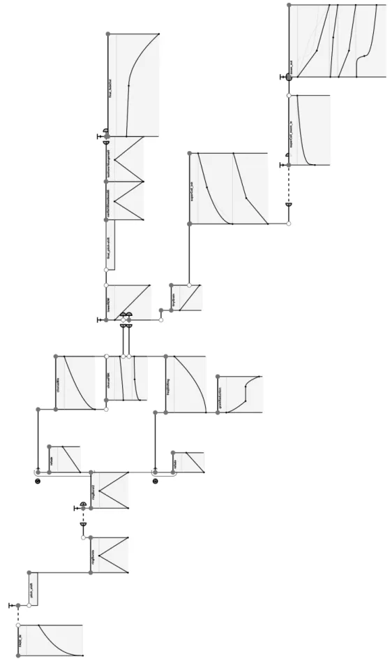
Next we detail the elements defined in the visual model of i-score. The graphical elements shown in the following figures, like Figure 1, are screen captures of i-score in which the colors were changed to adapt them for printing. Moreover, we will use italic font in this paper for elements of the visual model of i-score.
• A Time Constraint defines a non-null span of time whose duration is not necessarily fixed.
• A Condition starts or disables its following Time Constraints according to the evaluation of a Boolean expression.
• A Time Node synchronizes the Time Constraints that end on it and the Conditions that start on it. It may contain a Trigger, i.e., an expression which will trigger the Time Node when it becomes true. For instance, Figure 2 illustrates a Time Node with a Trigger. The presence of a Trigger in a Time Node decides if the previous Time Constraints are defined with either a fixed or a flexible duration.
• A State is a container for data to send (e.g., OSC messages). It is similar to a cue.
• A Process is a pair(f , s) where f is a function that is called at each clock tick, and s is a fixed State on which f operates. For instance, s can be the definition of a curve or Javascript code. f takes the current time as argument and returns a State.
The above elements can only be combined in specific ways in order to reduce complexity. However, this causes no loss of expression power. The properties of each element can be edited via a graphic inspector. The authoring rules are as follows:
• A Process must be attached to a Time Constraint.
• If a Boolean expression is not specified, the default value is true.
• Time Constraints need to be attached to a Condition at their beginning, and to a Time Node at their end. However, they are defined between two States when authoring Sequences (see Figure 3).
• A State must be attached to a Condition.
• Multiple Conditions can be synchronized by a single Time Node.
It is important to note that i-score automatically enforces these rules during the authoring process. For instance, the command CTRL-Click in an empty place of a scenario will create a group containing a Time Node and a State. Moreover, it also will create a Time Constraint between the created State and either the latest selected State or the starting State of the scenario if there is none.
The rules described above define a Scenario, that is itself an implementation of a Process. The notion of
Scenarioallows to implement hierarchy easily as it is shown in Figure 4.
2 The inter-media sequencer i-score 5
2 The inter-media sequencer i-score 6
Figure 2: Example of a Time Node with a Trigger, a previous Constraint, and two Conditions. The Condition at the top has a single following Constraint while the Condition at the bottom has two following Constraints.
Figure 3: Example of a Sequence in i-score. It consists of two Constraints and one State between each of them. If these two curves refer to the same parameter, moving the last point of the first will move the first point of the second. If one clicks on the middle State, it will look like a single value if there are curves referring to the same address on each side.
Figure 4: Example of a hierarchical score. A Time Constraint contains a Scenario which contains other Time
Constraints. There is no enforced limit on the nesting level.
2.2
Execution semantics
The execution in i-score operates by means of a scheduler that works at a fixed rate and that can be set by the score’s author according to the needs of the score. At each tick, the scheduler recursively queries the current state of the Processes and tells them the current date. Then, the State is applied to the local device tree, which may in turn update the actual devices if the message is not filtered. Only the currently executing Processes are queried.
The Scenario, which provides the temporal semantics of i-score is itself a Process as described earlier. At each tick, the Scenario will make all its currently running Time Constraints tick recursively. Then, the Time
Nodesare evaluated. In order to know if a Time Constraint should start or stop in the current tick, i-score proceeds as follows:
• If a Time Node contains an expression, then it is triggered when both its expression becomes true and the time of execution which satisfies most of the previous Time Constraints is reached.
2 The inter-media sequencer i-score 7
• The Time Constraints that end on a Time Node are stopped.
• The Conditions attached to the Time Node are then immediately evaluated. If they are true, the next
Constraintsare launched. Otherwise, they are deactivated and everything behaves as if they had been removed from the score.
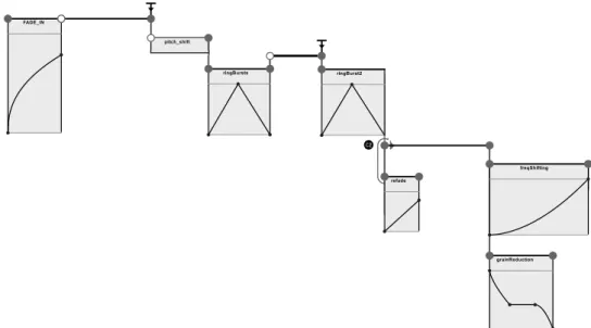
The above behavior is achieved with a mechanism inspired by the notion of passive tokens in Petri nets. We illustrate in Figure 5 two distinct executions for the first half of the score presented in Figure 1. Here, Figure 5a shows the execution of the score when the condition C2 at the end of ringBurst2 is satisfied while Figure 5b shows the execution when the condition C1 is satisfied. Additionally, the duration between FADE_IN and pitch_shift changes, as well as between ringBurst and ringBurst2 due to interactive triggering.
C2
(a) First play-through of the score: the bottom branch of the condition at the end of ringBurst2 was taken (i.e., condition C2 was satisfied).
C1
(b) Second play-through of the score: the top branch of the condition at the end of ringBurst2 was taken (i.e., condition C1 was satisfied), and both triggers started earlier.
Figure 5: Presentation of two possible executions for the first part of the score given in Figure 1. A section was disabled in either case by a condition (i.e., condition C1 or C2), and the duration between FADE_IN and pitch_shiftchanges, as well as between ringBurst and ringBurst2 due to interactive triggering. If both conditions had been false, the score would have stopped after ringBurst2 because there would be nothing to allow a transition to the second half of the score.
3 A Timed Automata model for interactive scores 8
2.3
The verification problem
The previous example offers interactivity, but only allows for a fixed ordering of events. For each pair of score elements, we can assert that one will occur before or after the other. However, i-score allows for more complex cases of interaction with the environment (e.g., the performer, external devices). Take for instance the score in Figure 6 in which due to the different events that can happen during the execution of the score, it may occur either that: B starts before A, B starts after A, or A and B do not start at all.
Figure 6: A score with many possible executions due to the usage of interactive features.
Hence, we are interested in providing to the artist the ability to check if some important invariants of a score are always maintained. For instance, they can relate to the reachability of a part of the score or the presence of a cohesive musical structure. We shall explain such invariants in more detail in Section 5.
3
A Timed Automata model for interactive scores
Timed Automata (TA) (Alur & Dill,1994) is a formalism for modeling and verification of time-critical systems. A timed automaton is a finite-state machine with a finite set of real-valued variables modeling logical clocks. These clocks are initialized with zero when the system is started, and then increase synchronously with the same rate. A transition in a timed automaton (represented by an edge) is labeled with a guard (i.e., when is it allowed to take and edge?), an action (i.e., what is performed when taking the edge?), and a set of clocks (i.e., which clocks are to be reset?). A location (represented by a node) is equipped with an invariant that constrains the amount of time that may be spent in that location. Therefore, invariants ensure the progress of the model while guards restrict the behavior of the timed automaton. Both invariants and guards are clock
constraintsthat are formally defined in Definition 1.
Definition 1 (Clock Constraint). A clock constraintδ over a set C of clocks is formed according to the grammar δ ::= x ≤ n | x < n | x = n | x > n | x ≥ n | δ1∧ δ2| true
where n∈ N0and x∈ C. Let Φ(C) denote the set of clock constraints over C, and Φl(C) the set of downward closedconstraints of the form x≤ n and x < n.
Clock difference constraints such as x− y < n, where x, y ∈ C and n ∈ N0, can be added at the expense
of a slightly more involved theory (Waez, Dingel, & Rudie,2013), hence they are omitted in this work. The formal definition of a timed automaton is as follows.
Definition 2 (Timed Automaton). A timed automaton is a 6-tupleA = 〈L, l0,Σ, C, E, I〉 where
• L is a finite set of locations, • l0∈ L is the initial location,
• Σ is a finite alphabet denoting actions, • C is a finite set of clocks,
3 A Timed Automata model for interactive scores 9
• I :L 7→ Φl(C) assigns invariants to locations.
A timed automaton is then a finite-state machine with a finite setC of clocks. Edges are labeled with tuples (g, α, D) where g is a clock constraint on the clocks of the timed automaton, α is an action, and D ⊆ C is a set of clocks. For simplicity, we write`−−−→ `g,α,D 0to denote that(`, g, α, D, `0) ∈ E. The intuitive interpretation of
`−−−→ `g,α,D 0is that the timed automaton can move from location` to `0when clock constraint g holds. Besides,
when moving from location` to `0, any clock inD is reset to zero and action α is performed. Function I assigns to each location an invariant that specifies how long the timed automaton may stay there. For location`, I(`) constrains the amount of time that may be spent in`. That is to say, the location ` should be left before the invariant I(`) becomes invalid. If this is not possible – as there is no outgoing transition enabled – no further progress is possible. As a progression of time is no longer possible, this situation is also known as timelock.
3.1
UPPAAL
Modeling practical systems often requires modeling features (e.g., parallel composition, urgency, atomicity) to capture a variety of system features. In the last decade, there have been a number of extensions to the original TA. In the following we shall give a brief introduction to the UPPAAL (David et al.,2015) tool and its modeling language, which has been used to model and analyze many real-time systems, e.g., audio protocols (Bengtsson et al., 2002), automotive systems (Kim, Larsen, Nielsen, Mikuˇcionis, & Olsen,2015;Lindahl, Pettersson, & Yi,2001), orchestration systems (Dong, Liu, Sun, & Zhang,2014), and multimedia systems (Echeveste, Cont, Giavitto, & Jacquemard,2013;Poncelet & Jacquemard,2015).
UPPAAL language is syntactically very rich and offers additional features such as parallel composition, bounded integer variables, structured data types, user defined functions, urgency, and atomicity. Moreover, UPPAAL allows for the verification of networks of timed automata using the method of model checking for properties specified in a subset of Timed Computation Tree Logic (TCTL) (Alur, Courcoubetis, & Dill,1993).
In UPPAAL, a system is modeled as a network of timed automata which is the parallel composition A1| . . . | Anof a set of timed automata A1, . . . , An, called processes, combined into a single system by the CCS parallel
composition operator (Milner,1989) with all external actions hidden. Synchronous communication between the processes is done by hand-shake synchronization using input and output actions while asynchronous com-munication is done by shared variables. To model hand-shake synchronization, the action alphabetΣ in Def-inition 2 is assumed to consist of symbols for input actions (denoted a?), output actions (denoted a!), and
internal actionsrepresented by the distinct symbolτ.
The UPPAAL model supports bounded discrete variables. They can be used as guards on the edges and also updated using resets. For a synchronization transition, the resets on the edge with an output label is performed before the resets on the edge with an input label. This destroys the symmetry of input and output actions. To model atomic sequences of actions, UPPAAL supports a notion of committed locations (represented with the symbol “C” on locations as shown in Figure 7) in which no delay is allowed. That is, if any process is in a committed location, then only transitions starting from them are allowed. Additionally, no clock constraints but predicates over variables are allowed to appear in a guard on an outgoing edge from a committed location. The notion of urgent locations (represented with the symbol “U” on locations as shown in Figure 7) are semantically equivalent to adding an extra clock x, that is reset on all incoming edges, and having an invariant
x≤ 0 on the location. Hence, time is not allowed to pass when the system is in an urgent location. Roughly, a committed location must be left immediately by the next transition taken in the system while an urgent location must be left without letting time pass, but allows interleaving by other automata.
Broadcast channelsallow to synchronize a process with an arbitrary number of processes. Any receiver able to synchronize in the current state must do so. If there are no receivers, then the sender can still execute the action. That means that the broadcast sending is never blocking. Finally, arrays, structures, custom types and user functions are allowed to be defined in UPPAAL either globally or locally to templates. These templates are timed automata defined with a set of parameters that are substituted for a given argument in the process declaration.
From now on, when talking about the TA model, we will implicitly refer to the model defined using the UPPAAL language.
3.2
Temporal relations
In the following we briefly introduce a TA model for interactive scenarios which we shall use for the verifica-tion of important properties of scenarios written in the software i-score. The reader can found more details
3 A Timed Automata model for interactive scores 10
of this model in (Arias, Desainte-Catherine, & Rueda, 2015). TA has been proven to be a formalism that is well adapted to the expression of the timing constraints appearing in an interactive score following sys-tem (Echeveste et al., 2013) because it is a powerful model for describing both the logical ordering of the events in such scenario and also the durations of events and the timing between them.
In i-score, the temporal organization of temporal objects (TOs) is defined by adding temporal relations (TRs) between them. These TRs are represented by Time Constraints in the graphical model of i-score. A TR imposes a precedence relation enhanced with a temporal constraint between two TOs. TRs are classified into
rigidand flexible. The former has a fixed duration while the duration of the latter is defined by an interval of time whose maximum duration may be infinite (i.e., it is not bounded). In the following we shall introduce the TA model for the specification of TRs. It is important to note that it is not necessary to define a model for a TR whose duration is zero (i.e., synchronization) because we can synchronize the starting/stopping of two or more TOs by means of complementary actions and broadcast channels.
Rigid temporal relation. We show in Figure 7 the timed automaton modeling a rigid TR. It starts in the state
idleand remains on it until the action event_s is triggered. This action starts the execution of the TR. Once this occurs, the timed automaton stays in the state wait until the durationγ0elapses (i.e., t = γ0). Notice that the above behavior represents the delay generated by the TR or the Time Constraint in the visual model of i-score. Once the delay expires, the timed automaton moves to the state finished and triggers the action
event
_e
1and at the same time-unit the actionevent
_e
2denoting, respectively, the elapsing of the duration and the stopping of the TR. These events may define the starting or the stopping of other timed automata (e.g., other TOs).t≤ γ0 idle wait skipped finished killed t≥ 0,event s?,{t = 0} true, kill p?,∅ true,kill p?,∅ t r u e , sk ip p ? , ∅ t = γ 0, ev en t e 1 !, ∅
true,skip!,{t = 0} true,event e2!,{t = 0}
true,kill!,{t = 0}
Figure 7: Timed automaton modeling a rigid temporal relation of durationγ0.
In i-score when a Scenario stops all its children must immediately stop. Then, a TR is “killed” by the action kill_pthat is triggered by its parent at any state of execution. Moreover, the timed automaton triggers, at the same time, the action kill in order to suddenly stop other timed automata that are its “children”. As we shall see, the above is important when we use the model for TRs to specify TOs defining hierarchical structures (i.e., Scenarios in the visual model of i-score). Later, we shall introduce the actions skip_p and skip.
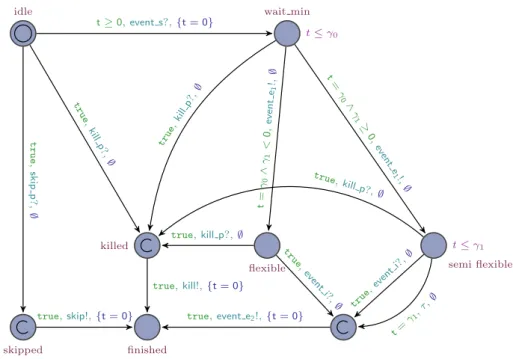
Flexible temporal relation. We next introduce in Figure 8 the timed automaton modeling a flexible TR.
Similar to the above model, the timed automaton starts in the state idle and moves to the state wait_min when the action event_s is triggered. It stays in that state until the minimum durationγ0elapses (i.e., t= γ0). Once this occurs, the timed automaton triggers the action
event
_e
1and goes either (case 1) to the state flexible if the maximum durationγ1is infinity (i.e.,γ1< 0), or (case 2) to the state semi_flexible if the maximum duration is bounded (i.e.,γ1≥ 0). The actionevent
_e
1may synchronize with other timed automata waiting for the elapsing of the minimum duration of the TR.In the second case, the timed automaton waits for either the elapsing of the maximum durationγ1(i.e., t=
γ1), or the triggering of the action event_i which stops the TR. In the first case, it only waits for the trigger-ing of the action event_i to stop. As we shall see later, the action event_i can represent the triggertrigger-ing of an interaction point or the stopping of other TR. Once the TR finishes, the action event_e2 is immediately triggered in order to notify the stopping of the TR. The remaining actions and states of the timed automaton denote the same as in the model of a rigid TR.
Handling temporal relations. Composers usually define the start time of TOs by means of one or more TRs.
Intuitively, having several TRs defining the starting of a TO is equivalent to have a TR whose minimum duration is defined by the elapsing of the minimum durations of all TRs and whose maximum duration is defined when
3 A Timed Automata model for interactive scores 11
t≤ γ0
t≤ γ1
idle wait min
skipped finished
killed
flexible semi flexible
t≥ 0,event s?,{t = 0} t r u e , sk ip p ? , ∅
true,skip!,{t = 0} true,event e2!,{t = 0}
true,kill!,{t = 0} tr ue, kill p?, ∅ true,kill p?,∅ tr ue, even t i?, ∅ true, kill p?,∅ true ,ev ent i?,∅ t = γ1, τ,∅ true ,ki llp? ,∅ t= γ0 ∧γ 1 < 0, even te 1 !,∅ t= γ 0 ∧ γ 1 ≥ 0, ev ent e1 !, ∅
Figure 8: Timed automaton modelling a flexible temporal relation with minimum durationγ0and maximum durationγ1. γ1< 0 means that the maximum duration is infinity while γ1≥ 0 means that it is bounded.
one of them stops. Therefore, it is important to have a mechanism to ensure the temporal constraint imposed by several TRs.
We present in Figure 9 a timed automaton responsible for maintaining these complex temporal constraints that are imposed by n> 1 number of TRs. Therefore, the model is parametric to a number n of TRs. The timed automaton starts in the state idle and waits for either the triggering of the event
event
_s
1orevent
_s
2. The former represents either the elapsing of the duration of a rigid TR or the minimum duration of a flexible TR (i.e., actionevent
_e
1in Figure 7 and Figure 8) while the latter denotes the stopping of a TR (i.e., actionevent
_e
2in Figure 7 and Figure 8).It increments the variable counter by one (i.e., counter++) each time a TR reaches its (minimum) du-ration. This behavior is repeated until all TRs have reached their (minimum) duration (i.e., counter = n). Once this happens, it moves to the final state and immediately triggers the action event_e allowing for the synchronization with other timed automata (e.g., starting of listening for an external event or starting a TO).
idle error finished tru e, even ts 2 ,∅ tr u e, k ill p ? , ∅ true,skip p?,{cou nter+ + } true, events 1?, {counter + + , skip v = false} counter < n,τ, ∅
counter = n∧ skip v = false,event e!,∅
counter = n∧ skip v = true,skip!,∅
Figure 9: Timed automaton for handling several temporal relations.
It is important to note that the timed automaton reaches the error state error if a TR stops before all TRs have reached their (minimum) duration. That is, the temporal property defined by the TRs cannot be satisfied by a possible execution of the scenario. The local variables counter and skip_v are initialized with values 0 and true, respectively. The action kill_p denotes the same behavior as we have already explained and skip_pwill be described later.
3 A Timed Automata model for interactive scores 12
3.3
Guarded interaction points
Intuitively, a guarded interactive point (IP) waits for events asynchronously triggered by the environment (e.g., the performer) during the execution of the scenario and evaluates the sending values with conditions defined by the composer (i.e., branching behavior) in order to enable the starting or the stopping of a TO. We recall that the system should maintain the temporal constraints defined by the TRs each time an IP (i.e., a
Triggerin the visual model of i-score) is triggered.
Let us explain the notion of guarded IP through the following example. Assume that a TO has an IP that allows to anticipate or delay its starting and it can be triggered only if the temperature of the environment is greater than 20oC. Therefore, the IP can only be triggered if both (1) the event is sent between the minimum and the maximum duration of the TR defining the start time of the TO, and (2) the value carried by the event (i.e., the temperature) satisfies the guard (i.e., temperature> 20). Moreover, the composer can decide if the IP is triggered automatically (i.e., urgent behavior) or not (i.e., non-urgent behavior) by the system, in the case where the maximum duration of the IP is reached. Observe that the skipping of the triggering of an IP will cause the omission of the execution of the branch.
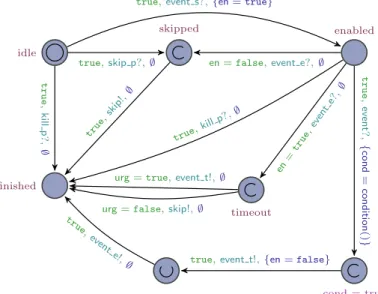
After the introduction of the intuitive notions, we are ready to present the timed automaton to model a guarded IP. As we can see in Figure 10, the timed automaton begins in the state idle and waits for the action event_s in order to move to the state enabled and start listening to the events sent by the environment (e.g., the performer). We recall that the action event_s is synchronized when all the preceding TRs have reached their minimum duration. Then, the timed automaton remains “listening” to the event until either (1) the action event_e is triggered or (2) the value carried by the event event satisfies the condition. Case 1 represents the case in which the IP is not triggered or the value does not satisfy the condition within the interval of time defined by the TRs. Thus, depending on the behavior defined by the composer (i.e., urgent or non-urgent), the execution of the branch will be omitted (i.e., action skip) or the IP will be triggered immediately (i.e., action event_t). Finally, the timed automaton moves to its final state.
On the other side, case 2 represents the case in which the IP is triggered because the event is sent within the interval of time defined by the TRs and the guard is satisfied (i.e., the function condition returns true). Therefore, the IP is triggered (i.e., action event_t), and at the same time, the action event_e is triggered in order to stop the TRs controlling the temporal interval in which the IP can be triggered. The action kill_p denotes the same behavior as we have already explained.
idle
finished
skipped enabled
timeout
cond = true
true,skip p?,∅ en = false,event e?,∅
true,event s?,{en = true}
en =tr ue, even te? ,∅ t r u e , k ill p ? , ∅ true ,sk ip!, ∅ true, killp?, ∅
urg = true,event t!,∅ urg = false,skip!,∅
t r u e , ev en t? , { co n d = co n d it io n () }
true,event t!,{en = false}
tr ue,
event e!,∅
Figure 10: Timed automaton modeling a guarded interaction point.
Function condition is a local function that allows to know whether a condition is satisfied or not. This function only accepts conditions of the form “msg op_id value” where the variable msg is a shared variable storing the value carried by the event sent (i.e., action event) while op_id and value are parameters of the timed automaton denoting respectively a boolean operation and an integer value. For instance, to specify a guard saying that the value of the event (e.g., the temperature) must be less than 20, we set op_id = 2 and value = 20, i.e., msg < 20.
The remaining states are introduced through the following example. Assume that two temporal objects, phraseA and phraseB, control the playing of two different musical phrases whose starting depends on the
3 A Timed Automata model for interactive scores 13
lightning of a room (i.e., an event that sends either light or dark). Thus, each TO has a guarded IP listening for the same event during the same interval of time. However, the defined conditions are mutually exclusive and only one IP will be triggered while the other one will be omitted. In this regard, the shared variable en is used as a global flag for a set of synchronized IPs listening for the same event. The value of en is changed to falsewhen one of these IPs is triggered. Thus, the IPs whose condition was not satisfied are skipped (i.e., the timed automaton takes the transition from the state enable to the state skipped with the guard en = false and action event_e).
We recall that the skipping of the execution of a branch causes that all TRs and TOs of the branch will be skipped. For this reason, each timed automaton presented so far models the above behavior by leaving out its execution when the action skip_p is triggered. Furthermore, the timed automaton propagates the skipping of the branch by triggering the action skip that is synchronized with the action skip_p of other timed automata.
3.4
Interaction
Composers allow the environment (e.g., the performer) to interact with the scenario during performance by adding IPs (i.e., Triggers and Conditions in the visual model of i-score). This interaction is carried out by send-ing messages to the system asynchronously. We model this non-deterministic environment ussend-ing the timed automaton in Figure 11. Intuitively, it triggers the action event (i.e., it sends the event) with an attached value (i.e., the parameter val) that is globally communicate by means of the shared variable msg. The action is triggered at a non-deterministic time (i.e., the transition is not guarded by clock constraints or synchro-nized with input actions) and it is synchrosynchro-nized with time automata representing IPs waiting for this event. Many copies of this timed automaton may be instantiate in order to represent different interactions with the environment.
idle finished
true,event!,{msg = val}
Figure 11: Timed automaton modeling the non-deterministic interaction of the environment. The shared vari-able msg allows the asynchronous communication between the environment and the system. The parameter valrepresents the value attached to the event.
3.5
Multimedia processes
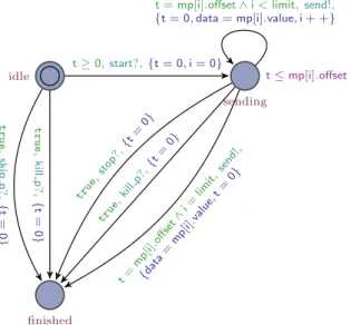
It is important to note that i-score does not execute multimedia processes (i.e., Processes in the visual model of i-score), but it sends, during execution, parameters (i.e., values) to external multimedia applications, such as Max/MSP and PureData. Intuitively, in the TA model a multimedia process is modeled as a list of values (parameters) associated with a synchronization time at which they should be sent. As an example, imagine a multimedia process controlling the brightness of a lamp and which consists of seven parameters sent pe-riodically to an external device. Additionally, each parameter pi is sent at∆ time after sending pi−1when i≥ 1 or after the starting of the constraint controlling its duration when i = 0 (i.e., intra-stream
synchronisa-tion(Blakowski & Steinmetz,1996)).
As shown in Figure 12, the timed automaton starts in the state idle and the beginning of the multimedia process is synchronized with the starting of a specific TR by means of the action start. Once this occurs, the timed automaton goes to the state sending in which the list of parameters of the multimedia process mp (i.e., mp[i].value) begins to be sent respecting their time of synchronization (i.e., t = mp[i].offset). The action send denotes the sending of the corresponding parameter to the external application by means of the shared variable data. The list of parameters is traversed using the local variable i which is initialized in 0 and incremented by one (i.e., i++) each time a value is sent. The multimedia process stops (i.e., it goes to the final state finished) either if the action stop is synchronized with the stopping of the TR defining its duration or when all parameters have already been sent (i.e., i = limit). The actions kill_p and skip_p denote the same behavior that we have already explained.
3.6
Hierarchy
Intuitively, a Scenario in the visual model of i-score defines the temporal organization of a set of TOs in which TRs can only be defined between TOs in the same hierarchy level (i.e., scope). We can specify Scenarios as
3 A Timed Automata model for interactive scores 14 idle finished sending t≤ mp[i].offset t≥ 0,start?,{t = 0, i = 0} t r u e , k ill p ? , { t = 0 } t r u e , sk ip p ? , { t = 0 } true ,ki llp? ,{t =0} true ,st op?, {t= 0} t= mp[ i].off set ∧ i = limit, send !, {dat a= mp[ i].va lue, t= 0}
t = mp[i].offset∧ i < limit,send!, {t = 0, data = mp[i].value, i + +}
Figure 12: Timed automaton specifying a multimedia process.
flexible or semi-flexible TRs with an attached set of TOs (i.e., their children). Roughly, in the case of a Scenario with an IP defining its duration (i.e., an IP at the end), the Scenario can be modeled as a flexible or semi-flexible TR depending on its maximum duration (i.e., bounded or infinity) and an IP with urgent behavior. Since the stopping of a Scenario also must stop its children, we use an auxiliary timed automaton (see Figure 13) to synchronize the action kill_p of its children (i.e., action
event
out of the auxiliary automaton) with the stopping of the Scenario (i.e., actionevent
in of the auxiliary automaton). Notice that the kill behavior is propagated down the hierarchy stopping all descendants of the Scenario. This is possible because the timed automata defined so far are killed when their action kill_p is triggered, and at the same time, they trigger the action kill in order to stop their own children.idle finished tr u e, kill p, ∅ tr u e, sk ip p, ∅ true,eventin,∅ tru e, even tout ,∅
Figure 13: Auxiliary timed automaton to stop the children of a structure.
On the other case, a Scenario with a rigid duration (i.e., with no IP at the end) is modeled as a flexible TR whose minimum duration represents the duration of the Scenario and whose maximum duration is infinity. These considerations are necessary because the Scenario must wait for both its duration and the stopping of all its children. Therefore, we use the timed automaton defined in Figure 9 in order to stop the Scenario by triggering its action event_e (see Figure 8) when both all its children have stopped and the Scenario has reached its minimum duration.
3.7
Hierarchical interactive multimedia scenarios
To conclude, a hierarchical interactive multimedia scenario is a network of timed automata representing the execution in parallel of the TOs and TRs defined by the composer in the score, and whose start and stop times are defined during execution by the synchronization among them. Hence, as we saw before, the whole score is modeled as a scenario containing TOs and TRs. Additionally, it has an IP at the start that is triggered by the environment, e.g., the performer pressing down the play button.
4 Verification of interactive scores: transformation of the visual model into Timed Automata 15
4
Verification of interactive scores: transformation of the visual model
into Timed Automata
In this section we shall present how to translate interactive scores written in i-score into the TA model presented above. It is important to note that only a strict subset of i-score scores can be translated into our TA model. This limitation is because i-score is based on a plug-in architecture which is easily extensible. For instance, a plug-in allowing to run arbitrary Javascript code at each clock tick is offered in i-score. For that reason, we shall only describe the core plug-ins that provide the temporal model and the automation curves.
We present the definitions and relations between automata that are necessary when converting an i-score score into TA. For each TA template, the required parameters of the created automaton are given in a table with the left column being the required variable and the right column being the value. When a parameter is specified as “innate”, it means that a new variable or a new broadcast channel is created.
Technically, i-scorescores are represented as a tree which depicts the following hierarchy: • A Time Constraint contains Processes.
• A Scenario is a Process.
• A Scenario contains Time Constraints.
• The root of an i-score document is a Time Constraint.
A Scenario has a starting Time Node which cannot be moved. It is triggered automatically when the Process starts.
The elements presented in section 2.1 are chained together inside a Scenario via identifiers. This temporal chaining does not constitue a tree, due to the presence of conjunctions.
Besides, only the elements for which there is a path from the starting Time Node will be executed. This allows to have multiple “programs” in a Scenario, some of which are not linked to the beginning and hence will not be executed.
We study the main program of a Scenario in order to build the TA model of a score. As we saw above, it consists in the connected graph that contains the starting Time Node of the Scenario. Therefore, it is only necessary to traverse this tree to generate the corresponding TA model. Since the created model is a function of the current state of the Scenario, we can give a consistent naming scheme to the TA elements, such as the broadcast channels.
We choose the path of the corresponding elements in i-score with a relevant prefix if there are more than one automaton for a single i-score object. This simplifies the program and also allows an automaton to refer to another that has not been created yet. The automata are then exported into a file recognized by the UPPAAL model-checker.
Before presenting the TA encoding of the i-score elements, let us define some functions used by the parser: • pt(C) is a function which for a TR or an IP returns the timed automaton representing the previous Time
Node.
• nt(C) is a function which for a TR returns the timed automaton representing the following Time Node. • pp(C) is a function which for a TR returns the previous Interaction Point timed automaton.
• np(C) is a function which for a TR returns the following Interaction Point timed automaton. • nc(C) is a function which for a TR returns the following Control timed automaton.
• par(C) is function which for a TR returns the timed automaton representing its parent.
The TA encoding follows the same logical organization than the visual model. That is, the elements of the visual model are each translated to one, or multiple TA according to their role. Hence, references to previous and following elements in the TA domain, such as Control or Interaction Point automaton, should be considered as a shorthand for the previous and following elements of the visual model that they map to.
Conditions and data. Contrary to the visual model, the TA model is only able to represent simple conditions
defined as follow:
4 Verification of interactive scores: transformation of the visual model into Timed Automata 16
where operator is either=, 6=, ≥, ≤, <, >, and where message and value are integers.
In addition, the visual model allows for the authoring of arbitrarily nested Boolean expression and supports several types for manipulating data, such as integer, floating point, Boolean, string, and tuples, which are types used in OSC messages. For instance, an expression in i-score could be:
(a:/b >= 30 && a:/b < c:/d) || (e:/f/g == [1, [2, "hi"], 'X', 3.14])
Hence, if we want to model conditions in the TA model, we have to limit i-score to integer-based States and Processes.
Time Constraint. We model a Time Constraint using either the Rigid automaton or the Flexible automaton.
The former is used when the duration is known beforehand, otherwise the latter. We present the mapping of a Time Constraint with rigid duration to the TA model in Figure 14.
Parameter Value event_s pp(C).event_t event_e1 np(C).event_s event_e2 np(C).event_e skip_p pp(C).skip kill_p par(C).kill skip np(C).skip_p kill innate
(a) Constraint C which ends alone on a
Time Node. Parameter Value event_s pp(C).event_t event_e1 nc(C).event_s1 event_e2 nc(C).event_s2 skip_p pp(C).skip kill_p par(C).kill skip nc(C).skip_p kill innate
(b) Constraint C which ends with other
Con-straintson a Time Node. Figure 14: TA definition for Time Constraints.
The mapping is similar for Time Constraints with flexible duration. However, we have to set the following additional variable in order to stop the Time Constraint either when the Trigger is triggered or when multiple
Time Constraintsend on the same Time Node.
e v e n t _ i = np ( C ). e v e n t _ e
Time Node. We model the Time Node as a Interaction Point automaton. In the most basic case, where a Time Nodehas no Trigger and a single previous Time Constraint, all the variables are innate.
On the other hand, when a conjunction is present (i.e., multiple Time Constraints end on the same Time
Nodeas is shown in Figure 15), we have to introduce a Control automaton that will check the range of each
Time Constraintand trigger the Time Node accordingly. Intuitively, the Control automaton waits for the elapsing of the minimum duration of all Time Constraints and once this occurs, the Time Node is executed. However, if a Time Constraint finishes (i.e., it reaches its maximum duration), then the Control automaton moves to an error state. This error state denotes the unsatisfiability of a Time Constraint imposed by the composer.
Figure 15: An example of conjunction where two Time Constraints define the interval of time in which the
Triggercan be triggered.
The i-score software takes care of transforming automatically the Time Constraints of a conjunction into
Time Constraintswith flexible duration in order to prevent two problems:
• The evaluation interval will be the intersection of all the incoming Time Constraints. Hence, a Time
Constraintwith fixed duration would prevent the presence of any evaluation interval, which means that there would not be any kind of interactivity involved.
4 Verification of interactive scores: transformation of the visual model into Timed Automata 17
• The problem of propagated synchronization that is illustrated in Figure 16.
Figure 16: Example of a bad conjunction. An invalid state could happen if the topmost Time Constraint triggers too late, because in this case the ending of the two Time Constraints below will not be able to be synchronized. To prevent this, by default, i-score removes the maximum duration of Constraints converging on a Time Node. This is due to the lack of a proper CSP solver that would be able to infer correct maximal durations for the converging elements.
Condition. In the TA model, IPs are guarded by conditions. Therefore, an IP is triggered if the event sent by
the environment (e.g., the performer) contains a value that satisfies the condition defined by the composer. In i-score, Conditions are not evaluated when an external event is triggered, but they are evaluated at a specific instant of time defined by a Time Node. In that case, it is necessary to start the evaluation of the Condition when the Time Node finishes. In order to avoid causality problems in the TA model, we delay the sending of the external event in a logical time-unit by using the Mix automaton. We present the mapping of a Condition to the TA model in Figure 17.
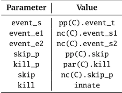
Parameter Value id innate value innate en true msg innate event innate urg true event_s pt(P).event_e skip_p pt(P).skip event_e innate kill_p par(P).kill skip innate event_t innate (a) Interaction Point P corresponding to a
Condition. Parameter Value event_in pt(P).event_e event_out P.event_e skip_p P.skip_p kill_p P.kill_p (b) Mix automaton settings when there are no Conditions.
Figure 17: Definition of the TA for a Condition.
Conjunctions. A conjunction of Time Constraints is modeled by a Control automaton. When it is present, the
corresponding Interaction Point automaton of the Time Node is modified as shown in Figure 18.
Parameter Value event_s1 innate skip_p innate skip innate event_e innate kill_p scenario.kill event_s2 innate
(a) Control automaton.
Parameter Value
skip_p c.skip event_e c.event_s2 event_s c.event_e (b) Transformation of a Interaction Point automaton after a Control c.
5 Evaluation 18
Hierarchy. In the visual model, the hierarchy is implemented via encapsulation and polymorphism of the Processes. A Time Constraint contains zero to many Processes, and the Scenario is itself a Process. This is important because it provides easy operations of standard GUI behaviors: copy- paste, etc. Also, in this way, a Scenario can be stored on a library of components in order to be reused later. When the execution of a Time
Constraintstarts, the execution of all of its child Processes starts at the same time.
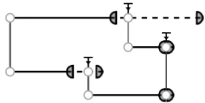
In the case of hierarchy in the TA model, we simply connect the start event of the first Time Node of the hierarchical Scenario in order to start the time automaton representing its parent Time Constraint. The above allows for the same kind of synchronization. We illustrate this distinction in Figure 19.
(a) Hierarchy in i-score. The elements in the box are completely unrelated to the elements in the parent scenario.
(b) Hierarchy as it behaves in TA: all the ele-ments are part of the same graph.
Figure 19: Hierarchy representation in the visual and TA model of i-score.
5
Evaluation
In this section we study the use of the presented framework and its performance. The translation of interactive scores into the Time Automata model has been implemented directly in i-score. For the sake of verification, we implemented a procedural score generator in order to test the system with a random number of objects. Moreover, we created for each Trigger a non-deterministic event Event_ND in order to model all possible interactions with the environment.
5.1
Specification of properties
The verification of scores is carried out by using the UPPAAL model-checker, which allows to use a subset of the Timed Computation Tree Logic (TCTL) (Alur, Courcoubetis, & Dill,1990) for the specification of the properties to be verified. The semantics of TCTL is defined over the infinite tree containing the states and transitions of the unfolded transition system of a TA network. In this regard, formulas in TCTL consist of state and path formulas. The former describe properties that can be checked locally on a state (i.e., boolean expressions over predicates on locations and integer variables, and clock constraints), whereas the latter quantify over paths or traces of the model.
Roughly speaking, the quantifier∀ denotes that a given property should hold for all paths of the tree while the quantifier∃ denotes that there should be at least one path of the tree where the state property holds. The symbols and ♦ are used to quantify over states within a path. denotes that all states on the path should satisfy the property, while♦ denotes that at least one state in the execution satisfies the property. For better understanding, we illustrate the different path formulas supported by UPPAAL in Figure 20.
Next, we present some examples of useful properties of interactive scores:
• The temporal exclusivity property of two Time Constraints A and B can be checked with: ∀ (¬A.wait ∨ ¬B.wait)
This property says that in all possible executions of the score, always both A and B are not present in the same state. For instance, checking this property is very important if a multimedia device only can be used by one automation at the same time.
5 Evaluation 19
(a)∀ φ. In all execution paths of the system, always the propertyφ holds.
(b) ∃♦ φ. The property φ
possi-bly can be satisfied by any reachable state.
(c)∀♦ φ. In all execution paths of the system, eventually the propertyφ is
satisfied.
(d)∃ φ. In at least one execution path, always the propertyφ holds.
φ
φ φ φ
ψ
(e)ψ φ. Whenever ψ is satisfied,
then eventuallyφ will be satisfied.
Figure 20: TCTL path formulas supported by UPPAAL. The filled states are those for which a given state formulaφ holds.
• The unreachability of error states can be checked with: ∀ ¬A.error
It says that in all possible executions of the score, A never reaches an error state. This property is important if we want to check that a temporal constraint is always satisfied.
• Since our scores are finite (i.e., we have no loops in the TA model) we can check that a score eventually finishes with the following formula:
∀♦Scenario.finished where Scenario denotes the Process defining the main Scenario.
• Temporal properties can also be checked. It is possible to verify that a Time Constraint finishes before some amount of time:
∀♦Constraint.finished ∧ clock < 30000 where 30000 is the maximum time for ending the Time Constraint.
It is possible to extend the class of problems that we would like to verify. For instance, we can check re-source contention problems by labeling the Time Constraints with the rere-sources that are used in their Processes. Therefore, it becomes possible to generate a query that will verify the exclusion predicate for any of such Time
Constraints, and also properties of the form “all automations of the score are always executed 5 seconds after the
last”.
Another possibility stemming from the ability to annotate is the verification of musical-level structures. For instance, it is possible to assert that given an annotation of the Time Constraints relative to the part they pertain to (e.g., Intro, Chorus, Verse), the score’s structure satisfies a specific order. Such a property could be: the Intro is always followed by a Chorus. Given Cintro the Time Constraint annotated as Intro, and
Cchorus0, Cchorus1, . . . , Cchorusnthe Time Constraints annotated as Chorus, we can verify the following property:
Cintro.finished (
n
_
i=0
Cchorusn.wait) that means that when the Intro finishes, then eventually a Chorus should start.
5 Evaluation 20
5.2
Performance
In order to check the performance of our framework, we procedurally generated 100 times a set of 100 scores consisting of a random arrangement of Time Constraints of fixed duration, States, and Time Nodes.
For each score, we first measured the time taken to compute the mutual exclusivity property for each pair of
Time Constraints. Then, we computed the average mean time, the average maximum time, the average mean memory usage, and the average maximum memory usage for our set of scores. The results are presented in Figure 21 and Figure 22. These results were obtained with the use of GNU Parallel (Tange,2011) to reduce the computation time.
5 15 25 35 45 101 102 103 104 Num. Scenario T im e [m s, log sc al e]
Time per check Average max
Average mean
Figure 21: CPU time of the model-checking.
5 15 25 35 45 4 4.4 4.8 5.2 5.6 ·104 Num. Scenario Vi rt u al m em or y [K iB ]
Memory usage per check Average max
Average mean
Figure 22: Memory used by the model-checking. The test system consisted of a 64-bit GNU/Linux distribution with 64-bit UPPAAL, a Core-i7 2600k Intel processor, and 16 gigabytes of RAM. As can be seen, even though 100 scenarios have been generated, the scales only goes to a much lower maximum. This is because the computation time was growing exponentially high. For instance, a score of our set with 53 elements took an average of 800 seconds to solve a single query. In fact, UPPAAL was not able to handle computations for a single query past the 72th scenario since it started to crash. Optimization options6have also been tried but they do not impact the computation time in any meaningful manner. On the other hand, the memory usage was much easier to handle and it did not go over 50 MB during our tests.
Performance on a practical score. When a single property check is needed, the time taken for the
compu-tation is small enough to be realistically used by the composer, even if it is still not meant to be used as a real-time method.
For instance, a test mentioned above, for the ordering of musical parts, expressed in UPPAAL as:
Cintro Cchorus
can be checked in less than ten seconds on average on the score of Figure 1 which contains 31 Time Constraints. A simple optimisation can be achieved to make the state space smaller by recursively scaling the durations of the score’s elements. Since we are interested in logical properties of the score, the verification of these properties is not affected by the absolute duration of the elements described in the score. Therefore, we can safely divide all durations by some value, for instance 100. While this causes a loss of precision due to the 16-bit integer size used in UPPAAL, it allows to bring the check duration down to tolerable times.
For instance, while we are unable to complete any check with the score given in the score showcased in Figure 1 with its default duration (i.e., three minutes), if we scale it down to ten seconds most checks only take a few seconds and all the properties required are maintained. However, this approach may not be applicable for long scores with short separations between elements. That is, if there are multiple one-second parallel temporal relations in the score, and if the score lasts more than roughly 18 minutes (216/3600), then we will be unable to perform meaningful verifications since any downscaling could loose the temporal order information.
We shall present in the conclusions other mechanisms for reducing the state space of the verification.
7 Acknowledgements 21
6
Conclusion
In this paper we presented a Timed Automata model for interactive scores written in the inter-media sequence i-score. Unlike the existing models, the proposed model supports conditionals and provides a practical mech-anism for the verification of interactive scores.
We also showed some examples of the properties that can be verified, and we evaluated the time that UP-PAAL takes to perform such verifications. Currently, i-score can produce the list of elements that are annotated in i-score and generate the UPPAAL formula that will verify this property. Roughly, i-score produces a model file from the score that can be readily used with UPPAAL. However, the model has to be loaded manually in UPPAAL, or in the command-line checker verifyta. Besides, due to the specific license of UPPAAL (i.e., free only for use in an academic environment), the model checking cannot be distributed with i-score since it is under a GPLv3-equivalent license, CeCILL.
We found that the time taken for the verification is high (i.e., it is apparent for a human observer) as soon as there are more than forty elements in an interactive score. The computation time exceeds half a second on average, that may be too long in an interactive and reactive context: it would not be possible to run verifications each time the user performs an action in the graphical interface, to prevent invalid actions before they can happen with regards to the rules that the composer has chosen for the score. An asynchronous checking similar to the behavior of common integrated development environments, or grammar checking in word processing software may instead be possible. Moreover, there are multiple ways that would allow to improve performance since the problems are mostly due to the large state space generated mainly by Time
Constraintswith unbounded durations and the use of generic TA templates without an optimization process. To reduce the state space, we have the possibility to remove elements either on i-score side or on UPPAAL side. From i-score side, since we have all the required information on the score, we can adapt the generated automata by removing parts of the score that are unrelated to the property that we want to study. For instance, if we want to check if two Time Constraints could happen together, a simple way to prune the number of automata would be to check if they are connected by their respective end. If they are not, due to causality, we can remove from the model-checking all their following Time Constraints which may reduce the state space.
The conversion process from i-score to TA could also be optimized more. For instance, if there are no
Conditionsor Triggers at all, it would be superfluous to add Interaction Point automata. Then, the start and end of each Time Constraint with fixed duration could be linked directly together. Another opportunity for optimization lies in the use of a CSP solver to find for each non-deterministic external event, the minimal and maximal bounds of time at which it may be triggered. This would allow to reduce the state space further more since currently the interaction with the environment may occur at any point in time (i.e., a potentially infinity number of states).
From UPPAAL side, there are ways to reduce the size of the model, for instance, by using control flow analysis (Slomp,2010). Finally, users could themselves help the model checker in two ways:
• By arranging the score in a more abstract hierarchical scenario. Doing this, the model checker can be instructed to ignore hierarchy if the property to check is only relevant at a given nesting level. For instance, it is not necessary to create structures for each musical note if the property to check is at the musical section level.
• By setting “expected times” for some events of the score. For instance, if the property “Time Constraints
A and B will not happen together given that event E happens at ten seconds” is relevant for the composer, then she could set the elements of the score that depends on E at this time. Doing this, the model can use a timed automaton modeling a deterministic event instead of a non-deterministic event, reducing the state space and the computation time.
In (Poncelet & Jacquemard,2015), the authors present the application of model base testing techniques to verify interactive music systems. They translate scores into a Timed Automata network, which is then processed by tools from UPPAAL in order to generate covering suites of test cases. It would be interesting to apply the above approach to the domain of interactive multimedia systems (e.g., i-score) in order to compare the performance of the verification process in both approaches.
7
Acknowledgements
We thank the anonymous reviewers for their detailed comments that helped us to improve this paper. Also, we would like to thank Jean-Michel Couturier for his valuable remarks about the paper. This work has been