Publisher’s version / Version de l'éditeur:
Vous avez des questions? Nous pouvons vous aider. Pour communiquer directement avec un auteur, consultez la première page de la revue dans laquelle son article a été publié afin de trouver ses coordonnées. Si vous n’arrivez pas à les repérer, communiquez avec nous à [email protected].
Questions? Contact the NRC Publications Archive team at
[email protected]. If you wish to email the authors directly, please see the first page of the publication for their contact information.
https://publications-cnrc.canada.ca/fra/droits
L’accès à ce site Web et l’utilisation de son contenu sont assujettis aux conditions présentées dans le site
LISEZ CES CONDITIONS ATTENTIVEMENT AVANT D’UTILISER CE SITE WEB.
Technical Memorandum (National Research Council of Canada. Division of
Building Research); no. DBR-TM-30, 1953-08-01
READ THESE TERMS AND CONDITIONS CAREFULLY BEFORE USING THIS WEBSITE. https://nrc-publications.canada.ca/eng/copyright
NRC Publications Archive Record / Notice des Archives des publications du CNRC :
https://nrc-publications.canada.ca/eng/view/object/?id=823c1eb2-0205-40d7-b97f-5067531038e2
https://publications-cnrc.canada.ca/fra/voir/objet/?id=823c1eb2-0205-40d7-b97f-5067531038e2
NRC Publications Archive
Archives des publications du CNRC
Access and use of this website and the material on it are subject to the Terms and Conditions set forth at
Canadian Papers presented at the Third International Conference on
Soil Mechanics and Foundation Engineering
The Associate Committee on Soil and Snow Mechanics is
one of
about thirty special committees
which assist
the
National Research
Council
inits work.
Formed in
1945
to deal with an urgent wartime problem
involving soil
and
snow, the Committee is now performing its intended task
of
co-ordinating Canadian research studies
concerned with the
physical
andmechanical properties of the
terrain
of the
Dominion.
It does this through subcommittees on Snow and
Ice,
Soil Mechanics,
Muskeg,
and
Fermafrost.
The
Com-mittee,
which consists
of
about
fifteen
Canadians
ap-pointed as individualS
and not
as
representatives,
each
for a .3-year term,
has funds available . to
it for
making
research grants for work in its
fields of interest.
In-quiries will be welcomed
and should be addressed to:
The
Secretary, Associate Committee on Soil and Snow·Mechanics,
c/o
The Division of Building Research,
National
Research
Council, ottawa, Canada.
This publication is one of a series being produced by the Associate
Committee on Soil and Snow Mechanics of the National Research Council.
It may
therefore be reproduced, without amendment, provided that the Division is told
inadvance and that full and due acknowledgment of this publication is always made.
No abridgment of this report may be published without the written authority of the
T
NATIONAL RESEARCH COUNCIL
CANADA
ASSOCIATE
coセャャセitteeON SOIL AND SNOW
イセchanicsTECHNICAL 11EMORANDUM NO. 30
Canadian Papers Presented At The Third International
Conference on Soil I\1echanics and Foundation Engineering,
held in Zurich, Switzerland, August
1953
Ottawa
PREFACE
The Third International Conference on Soil
Mechanics and Foundation Engineering was held in
Zurich, Switzerland from June
16
to
27, 1953.
The
first such conference was held in
1936
as a part of
the tercentenary celebrations of Harvard University,
Cambridge, Mass.
The incidence of war necessitated
the gap of twelve years between the first two
meetings.
The second conference was held in Rotterdam,
Holland in
1948.
Seven Canadians were present at the Harvard
meeting and, despite the distance from Canada, five
Canadians attended the
rッエエ・イ、XセConference.
Six
Canadians were present at the Zurich Conference, of
which Dr.
N o'd
0HcLeod and FIr. 1tl.R
0Schrie ver repre
sen-ted Canada on the Executive Committee.
The Associate
Commi ttee on So il an d Snow l"lechanics of the Nat
Lon
al,
Research Council is pleased to publish these reprints
of the
six Canadian papers which '.vere presented at
the Zurich meetings and which are included in the
official Proceedings.
A Soil NechAnics Subcommittee has been
appointed by the Associate Committee; it consists of
regional representatives in the Maritimes,
セッョエイ・。ャLOttawa, Toronto, the Prairies Rnd British Columbia.
The Subcommittee has been designated as the Canadian
participating group in the International Society of
Soil Mechanics and Foundation
eイセゥョ・・イゥョァLwhich was
formed at the Rotterdam Conference.
The principal
function of this Subcommittee is to Assist in the
further development and application of soil mechanics
throughout Canada.
Inquiries with
r
er;
ar-d
to its work
will be welcome, they may be addressed to Mr. C.
Bo
cイ。キヲッイ、セ
Secretary, Subcommittee on Soil Mechanics,
Associate Committee on Soil and Snow MechAnics, c/o
National Research Council, Ottawa
2,
Canada.
Ottawa,
July,
19540
Robert
Fo
Legget,
TABLE OF CONTENTS
Settlement Studies on the National Museum
Building, Ottawa, Canada...
cセ bセCrawford
Prevention of Frost Heaving by Injection
of Spent Sulphite Liquor... .•.••••••
R. M. Hardy
Airport Runway Design and Evaluation in
Canada...
N. W. McLeod
Performance of a Steel Sheet Piling
Bulkhead.
I) • • • " • • • • • • • • • • • • • • • • • • • • • • • • •N. D. Lea
Steel Sheet Piling Studies...
J. L. Jaspar and
A. S. Ringheim
Study of Several Low Earth Dam Failures..
R. Peterson and
Reprinted from Proceedings of the Third International Conference on Soil Mechanics and Foundation Engineering, Switzerland 16th to 27th August 1953, Vol. I, Session 4
Proceedings edited by the Organizing Committee of the Third Conference, Gloriastrasse 39, Zurich 6 Printed by Berichthaus, Zurich
Session 4/5
Settlement Studies on the National Museum Building,
Ottawa, Canada
Etudes sur le tassement du Musee National du Canada
a
Ottawa
by CARL B. CRAWFORD, Assistant Research Officer, Soil Mechanics Section, National Research Council, Ottawa, Canada
Summary
The building for the National Museum of Canada is a four-storey structure about 400 feet long and 150 feet wide with heavy exterior walls of sandstone resting on spread footings. Since completion of the building in 1910, footing loads which vary from about
Ii
to 4 tons per square foot have caused a differential settlement of more thanIi
feet.Borings show that the building is underlain by about 50 feet of sensitive, compressible marine clay. Below thisisavariety of silty clays, clayey silts, and sands. Glacial till occurs at a depth of about 120 feet and bedrock at 132 feet. Regular engineering tests were per-formed on undisturbed samples obtained outside the influence of the building in order to determine grain size, strength, consolidation and plasticity characteristics of the soil.
An attempt is made to determine the cause of settlements and to compute settlements using soil mechanics theories. These move-ments are compared with actual settlemove-ments. Theoretical bearing capacity is compared with estimated actual bearing capacity. Com-ments are made on the existing foundation design and a design which would have been chosen for this building on the basis of modem practice.
The foundation problems of the National Museum Building in Ottawa, Canada, have interested engineers since 1910 when, after much difficulty, the structure was completed. One of the functions of the Division of Building Research of the National Research Council is to investigate building problems in Canada. Recently, the Division was given the opportunity of studying the foundation conditions of this interesting structure. This is a summary report of the results of the study.
Building Design
The Museum Building is a four-storey structure about400 feet long and 150 feet wide with heavy sandstone bearing walls
Sommaire
LeMusee National du Canada, construit en 1910,est un batiment de quatre etages d'a peu pres 400 pieds de longueur et 150 pieds de largeur avec de lourds murs exterieurs en gres taille se reposent sur des semelles
a
empattements. La charge des fondations, qui varie de 1,5a
4 tonnes par pied carre, a provoque des tassements differentiels de plus de 1,5 pieds.Les sondages ont revele que Ie batiment est situe sur une couche de 50 pieds d'argile marine tres sensible et compressible. Plus bas on trouve des argiles sablonneuses, sables argileux et sables fins. La moraine glaciaire commence
a
une profondeur de 120 pieds et la roche de fonda
132 pieds. Des essais standards ont ete faits sur des carottes de sondages provenant des forages situes en dehors de l'in-f1uence de la charge du batiment, avec Ie but d'obtenir la composition granulornetrique,la resistance au cisaillement et les caracteristiques de consolidation et plasticite,On a essaye de determiner les causes des tassements et de calculer les tassements probables en se basant sur les theories de la mecanique des sols. Ces mouvements ont ete compares avec les tassements actuels. La capacite portante theorique a ere comparee avec la capa-cite existante relevee,Les differences entre le projet des fondations realise et celui qui aurait ete choisi actueIlement, base sur la pratique modeme, ont etediscutees,
which rest on spread footings. As will be seen from the illus-trations, it is an example of Victorian architecture at its mas-sive best!
Since there is no record of the design loads for the Museum, a weight analysis of the Building was made to determine foot-ing loads on the soil. If the foundations were assumed to be completely flexible, unit loads up to
51
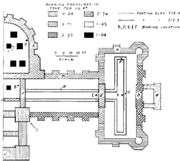
tons per square foot would exist. No doubt the heavy foundations are capable of considerable distribution of load and the calculated footing pressures are believed to be within 5%of the actual pressures. Load estimates made in 1915 are very close to those obtained in this study.ele-Fig. I Foundation Pressures in Tons per Square Foot Pression des fondations en tonnes par pied carre
vations and that unit loads vary widely. This has resulted in severe differential settlement. Fortunately, above the ground floor the internal structure is carried entirely on plate girders which span the exterior walls. This has allowed relatively uni-form settlement of the upper portion of the Building. The basement and ground floors, however, are supported on both exterior and interior footings and severe distortion of the floors and interior walls is evident.
Fig. 3 shows two typical failures of interior brick walls. These failures, although alarming in appearance, are not of great structural importance. The sub-basement floor is a strik-ing illustration of differential movement. The floor undulates from footing to footing and this aspect is often exaggerated by the springing-up of footings under archways where the load is interrupted. In one instance between two heavy pillars a con-tinuous footing had broken and had raised the floor by several inches. Consequently the sub-basement floor was of little use in determining actual settlements.
Settlements were noticed even during construction. By 1915 the tower at the front of the Building was out of plumb by more than a foot. Consequently, during that year the
settle-o
"A" Boring LE.G[.ND: bearェAvセ PR,E5$v,,"?£$' IN TON!i PER, sLセN sr. [[ill 4 0 4S
2'7" セ 3'11D
1·4, セ 3 Sセ • !·04 L_セoヲt Sc ....1-e.. kMfココア[Zf]]]]]]セエ]オ - - -セッッイAng !LEV 115,0 7,2·5 B,P,e..セ t ・orNinセ LvCATION'iment of the Building was carefully observed. In 1916 the upper portion of the tower was removed to prevent complete failure. Fig. 4 shows the building and, separately, the original tower. Observations indicate that little settlement of the Building has occurred since the tower was removed. For this reason pressures shown in Fig. 1 include the weight of the tower.
The total weight of the Building is about 65,000 tons of which less than 2%is live load. The weight of soil excavated was about 34%of the weight of the Building. The removal of the upper portion of the tower reduced the corresponding footing pressures by 35%.
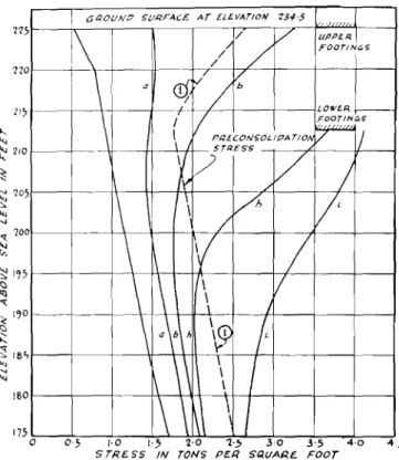
Stress distribution in the soil beneath various points was determined using influence charts (Newmark, 1942). For the determination of each point on the vertical stress profile four values were necessary: (1) stress due to original overburden, (2) stress due to upper footings, (3) stress due to lower foot-ings, and (4fnegative stress due to soil removed. Further com-plications were introduced by the variety of footing pressures. Several typical profiles of vertical stress with depth are shown in Fig. 5. The corresponding points under the building where stresses were computed are shown in Fig. 1.
All observations in this study were made for one-half of the building. This has simplified the study and is justified because the building is symmetrical in shape, loading, and actual settle-ment.
Soil Studies
Borings show that the Building rests on a 130-foot soil de-posit. The upper 50 feet consists of compressible marine clay which grades into clayey silt, sand and glacial till with in-creasing depth. This clay, deposited in an arm of the sea which invaded the region near the close of Pleistocene time, is com-monly called "Ieda clay" (Johnston, 1917). Itcovers a con-siderable portion of the populated regions of eastern Ontario and Quebec provinces.
Two borings were made at points A and C as shown in Fig. 2. In boring A, continuous sampling was carried out to a depth of 80 feet, using a 2-inch, thin-walled piston sampler. Intermittent split spoon samples were taken below this depth and rock was encountered at 132 feet. At boring C, continuous samples were secured to a depth of 45 feet using a thin-walled piston sampler. In addition to these two borings outside the influence of the Building, four borings were made from the sub-basement at pointsB, D, E,and F (Fig. 1)and undisturbed samples obtained. Owing to the variety of borehole and
foot-'c'80RIN" 0
5'£eTlON r"'<OUG" FOOTINGS
RRUセ
5E.CTION TilR.Ollvl{fooイエnHzセ AT 's-s'
2!U'S Fig. 2 Location of Borings A and C Relative
to Building
Emplacement des forages A et C par rapport au batiment
Fig. 3 Illustration of Typical Settlement Cracks in Basement Fissures caracterisuques dans la cave
ing elevations, all samples are referred to absolute elevation abovesea level in feet. The ground level around the building
isat elevation234.5.
Laboratory tests were performed on these samples and the results are shown in Figs.6to 11. Fig.6shows the results of grain size analyses of the samples from boringA. Several ran-dom tests on samples from the other borings agreed closely with these results. In no
case
did the percentage of the various fractions vary more than 7%and the average variation was 21%. Fig. 7 shows water contents, Atterberg limits and theCasagrande classification(Casagrande,1948)for samples fron. borings A and C. The average water content curve was ob-tained by averaging groups of data.
The hydrometer and Atterberg limit tests were performed on sample trimmings and are therefore averages for the sample. The clay was stratified with occasional silty layers. Inone
case,
at elevation 194.0 separate Atterberg limits were determined on two distinct layers and the results are shown in Fig. 7. Layers with more pronounced differences in properties are likely to be present.
Fig. 4 General View of Building Showing Portion of Tower Removed Vue generale du bitiment avec tour demotic
a
gaucheFig. 5 Vertical Stress Distribution under Typical Points
Courbes de pressions verticales sous points caracteristiques
Results of unconfined compression tests performed at a rate of strain equal to I% per minute on carefully cut specimens 3 inches high by
It
inches in diameter from A and C boring samples are shown in Fig. 8. The average curve, "A", was obtained by averaging groups of points. The actual strength is considered to be near the maximum values obtained as shown obtained as shown in curve"E",allowing for sample disturb-ance and fissures near the surface(Rutledge, 1944). The strength of the upper soils was greatly affected in the laboratory by fissures which it was thought would not appreciably reduce the in situ strength. Attempts were made to test remoulded spe-cimens but the sensitivity of the soil made this impossible.Several triaxial quick-tests were performed on samples in an effort to determine the effect of fissures on strength values but owing to apparatus difficulties these results are not reported. Consolidation tests were performed on undisturbed samples from all boreholes. Typical pressure versus void ratio curves are shown in Fig. 9. Two special tests were made using small loading increments and these showed the pre-consolidation load to be increased from 10%to J5%by slow loading.
Specific gravity of the soil particles was found to average about 2.83 with little variation throughout the top 50 feet. Unit weight determinations were made on strength and con-solidation samples and from these results overburden pressures were computed.
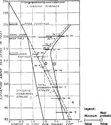
From consolidation test results two curves of the most probable preconsolidation loads are plotted in Fig. 10 together with total and effective overburden stresses. Two interpre-I GROllNO ,1IRFAC£ AT ELE.VAT/ON 234'5
.
. .,.1\
I /V
lIPPE.<i,I
/ //
FOOrtNGS / I\
aCI}
V/{,
-\
If-.I
LOWERf-rl;
\
PRE.CON,OL lOA TlONSTRESS \
/
/v
/
1\
I\
l/h
I'
I/
I\
1\
V
/
\
\
\/
\
/\
ab\h
|セ
f
1\
\
I
1\
\\ \
\.
\\
I
no II} 17.5 o 0'5 1·0 j.,5 2'0 1·,5 3·0 3'5 4'0STRESS IN TONS PER SQI./ARE FOOT 160 ....
""
セ 210 セ セ 105'"
'"
" 100 セ セ iセス <:l ttl"
• iセoセ
....
セ lee,",
4;1
V
}..,.,.
..,
\.J \) セ -r \:l C(セ
\) i:: ff> «"
Cl. >-- . . , :t \:l :t 00 ,,0 BY WE.I (,1..lT \ 8 0 R I N6 ,URFACE AT ELEV. 234'5I
'1
1 - - - _ 10 40 PE.RCENT 17",r---,--....,----.:r----,---..,...--, 180 175 o z o 1':'0 f-<1 > uJ ...J uJno
tl ", f-uJ UJ u, '210 -セ ..J セ '20", uJ 'I ...l <{ uJ '200 . _ -{flFig. 7 Variation of Water Content and Atterberg Limits with Depth Variation de la teneur en eau et limites d'Atterberg en fonction de la profondeur 2101--+---+-++'--7"1 セ a セ 160 160 21; ェMMMKMMMMKMMMMLセセNLMェ I;; 0 2; 50 7, lac PtR(£NT セBヲ 'NEIGIH 225r---r----r--...-..., 220ェMMMエMMMMKMMMエKMGセ」GMャ :<: セ 175 セ セ 170iMMッエMMKKセ -r-"'"H:--j セ I-...
'"
セ 200 t---+----+--+-+-c-セFig. 6 Distribution of Grain Size with Depth (M.LT. Classification) Distribution granulometrique en fonction de la profondeur
'I I \
セセ
[+\
セセuKMKKGエゥ
'++t-II
• >. 5 ..
7&,
I-a 2 3 4 5.. 7 HIOPRESSURE. (TONS PER SQUARE. FOOT)
1·00 1·20 I (:>I -70 ---,--- _l - -
--セ
160--1--1
1 - -.3'-'J QᄋXPヲMMMMセ 2-00 f---+--+-o0-,
'-0 ,-;, 1-0 VNeONl'lNEP Gompreセsion 5TREN6TH Htcyセ Pl./J, S'Q/./AR£ roor) GROUNP surセace AT ELE VAT/oN '134 '5 215 210 215 _a__•
7:0 "-セ 2°5...
<: ... 100...
セ セ QYセ'"
.... '" 190 セ 'J '<l 185 -c セ <:> セ r80 セ.... セ 175 170 Ii"Fig.8 Variation of Unconfined Compression Strength with Depth Variation de la resistance
a
la compression simple en fonction de la profondeurFig.9 Typical Pressure Void Ratio Curves
Courbes caracteristiques de I'indice des vides en fonction de la pression
tations of the method of preconsolidation are possible from test results. Curve (1), paralleling the effective overburden stress curve, indicates preconsolidation caused by overburden that has been removed during the history of the sediment. Curve (2), paralleling the total overburden stress curve, re-presents preconsolidation due to temporary lowering of the groundwater table causing natural consolidation during the history of the sediment. The slight displacement to the right would be due to subsequently stripped overburden.
As tests 36-7 and 36-9 are from boring A and tests 36-46 and 36-48 are from boring C,it is difficult to disregard these results. These two interpretations depend in part on the valid-ity of test results between elevations 205 and 213. If full weight is given to these results the second interpretation is more reasonable. If, however, they may be disregarded the first interpretation, curve (I), is more reasonable. Other test re-sults in the immediate vicinity support this interpretation. The lowering of the water table would therefore have had to be a local phenomena over a limited area. The opinion of geologists is that 20 or 30 feet of stripping by erosion is very likely in this region whereas temporary lowering of the groundwater table, although possible, is quite unlikely.
For these reasons curve(I)is considered to be the best inter-pretation of preconsolidation load and this curve is used for consolidation settlement calculations. The occurrence of fis-sures down to elevation 210 and the indication of desiccation
down to the break in the preconsolidation curve at elevation 213 is evidence that the groundwater table has been lower than it is now but not necessarily low enough to cause preconsoli-dation beyond curve (I).
Grain size and Atterberg limits test results (Figs. 6 and 7)
indicate that a drainage layer for consolidation occurs at ele-vation 184.0 or higher. Drainage can also occur at the footing elevations since the ground water table has been drawn down to the footings by artificial drainage.
Actual Settlement
When built, the elevation of the Museum Building was not related to a permament bench mark. Therefore, the absolute settlement of the Building has had to be estimated. Fortu-nately, level points were established in 1915 around the out-side of the building all at the same course of stone. Several level surveys were made during 1915using the entrances at each end of the building as references. Since 1949 an annual level survey of the original points has been made and many interior points have been added to the survey. By assuming that these entrances have not moved since construction it was possible to approximate the original elevation of all outside level points and therefore their subsequent settlement. By plotting present outside perimeter elevations and comparing these with present inside perimeter elevations, it was possible to approximate the
original ground floor elevation. By comparing ground floor elevations with basement floor elevations at points above one another at column locations (where movements should occur as a unit) it was possible to determine the original basement floor elevation. These comparisons were made for separate parts of the building and in each case the results were within 0.02 to 0.03 feet. With these original elevations determined, it was possible to use original and recent level points together to draw the contours of differential settlement.
Ifthe assumption of no movement of the end entrances was true, these contours would represent absolute settlement. How-ever, with this assumption, parts of the building which rest on
Computed Settlements
The total settlement of this structure probably consists of elastic, plastic, and consolidation settlement. An attempted evaluation of the contribution of each of these to the total settlement would be of little use in view of the limited informa-tion on the strength properties of this soil and the lack of facts concerning the early history of the building. Generally speak-ing, the footing loads exceed the elastic range of the soil so that elastic settlements would be followed by plastic deformation. Although the contribution of each is unknown, a considerable part of the settlement shown in Fig. 11 is thought to be due
Fig. 10 Variation of Overburden and Preconsolidation Stresses with Depth
Variation des pressions dues au poids du sol et preconsolidation en fonction de la profondeur
deep footings appeared to have risen 0.20 feet. Since there is no apparent reason why these footings which are loaded to 1ttons per square foot should rise, it was concluded that the entrances were dragged down by the main building. Careful observation of the entrances indicates that this is possible. Although the vertical stress under point "a"in Fig. 5 appears to be insufficient to cause settlement, it is based on the assump-tion of complete flexibility of the foundaassump-tion and may actually be increased due to stiffness of the structure. Therefore to ob-tain absolute settlement 0.20 feet were added to all contours shown in Fig. 11.
A comparison of elevations taken in 1915 and 1951 show that during that period an average settlement of 0.10 feet has occurred all around the Building except in the vicinity of the tower. Where the tower joins the Building no change in ele-vation has occurred since 1915 and at the outer edge of the tower the walls appear to have risen about 0.13 feet due to rebound after removal of the upper part of the tower.
contouセ intセセvセl
0-10Ff..E.T
Fig. II Measured Settlement Contours
Lignes de niveau des tassernents mesures
to these causes. A reasonably accurate estimation of the amount of consolidation settlement could probably be made by deter-mining the variation in water content immediately under several footings and comparing this with initial water contents. One of the purposes of making borings under the building was to make this comparison. Stress distributions show, however, that it is essential to obtain samples directly below the footings for this purpose. The size of footings and groundwater con-ditions make the procurement of these samples difficult but an attempt is planned.
Settlement computations based on the theory of
consolida-tion (Terzaghi,1943) were made for various selected points in
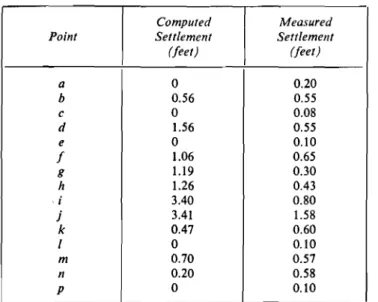
the building. The location of the points, atop, is shown in Fig. 1 and the computed settlements are shown in Table 1 tog-ether with estimated actual settlement. The actual settlement includes elastic and plastic deformation. Therefore the dis-crepancy between the actual and computed settlements is even greater than that shown in the Table.
Calculations of time versus degree of consolidation indicate that on the average 50% consolidation settlement will occur in 2 to 4 years and 80%will occur in 7 to 14 years after loading so that an explanation of the discrepancy by partially com-pleted consolidation is ruled out. Although this soil is quite impervious, the relatively short time required for almost com-plete consolidation can be understood by reference to the stress differences presented in Fig. 5 which show that most of the consolidation would occur within 10 or 12 feet of the footings. The most puzzling feature of the settlement of the structure occurs around the semi-circular part at the rear of the building, generally represented by points g and h in Fig. 1. Footing loads in this part are heavy and yet settlement has been small. Legend: 2-0 SQUARE SUP,FAC£ 1-0 IN tonセ 190ヲMMMKMMMMKM⦅⦅|⦅セ セ 710
'"
セ 705f---1----'+----+.--'"--+,---+---i "l'"
セ 2001---+----_-\ >::: セ セ QセU'"
Table I Comparison of Observed Settlement and Computed Con-solidation Settlement
Computed Measured
Point Settlement Settlement
(feet) (feet) a 0 0.20 b 0.56 0.55 c 0 0.08 d 1.56 0.55 e 0 0.10 f 1.06 0.65 g 1.19 0.30 h 1.26 0.43 i 3.40 0.80 j 3.41 1.58 k 0.47 0.60 I 0 0.10 m 0.70 0.57 n 0.20 0.58 p 0 0.10
A possible reason may be that the excavation was left open longer than usual and that drying increased the preconsoli-dation load.
The occurrence of silt layers is worthy of comment. It is believed that silt layers in clay will tend to spread out the load more than the elastic theory indicates (for example seeTaylor, 1948, or Casagrande and Fadum, 1944). Therefore, vertical stress profiles under the building were modified to conform approximately to the Westergaardtheory (seeTaylor, 1948) in view of the stratification of the soil. Use of the modified values reduced the computed settlements shown in Table 1 by about 20%. Silt layers would also permit lateral drainage for con-solidation and so allow more rapid settlement.
Bearing Capacity
Bearing capacity computations are complicated by the un-usual foundation outline of the building. Itis possible, how-ever, to obtain approximate values for ultimate bearing capa-city by assuming various equivalent rectangular footings. The following formulae (Terzaghi, 1943) were used for this com-putation:
(1) For local shear failure
q
=
eNc+
yDfNqwhere q
=
ultimate bearing capacity e=
cohesiony = unit weight of soil
Df = depth of footing below adjacent surface N,
=
5.7 for rp=
0Nq
=
1.0 for rp=
0where rp = angle of internal friction; (2) For general shear failure
q'
=
eNc'+
yDfN/where Nc'
=
3.8 for rp=
0Nq'
=
1.0 for 'P=
O.One-half the unconfined compressive strength was used for the value of cohesion. Maximum values were obtained using curve
"B"in Fig. 8 and minimum values were obtained using curve
"A" .
For comparative purposes the footings can be divided into four groups: (I)footings under the tower. (2) square footings under the centre of the building, (3) all remaining deep foot-ings, (4) all shallow footings. A comparison of computed values to actual bearing pressures is shown in Table 2. Itwill
Table 2 Ultimate Bearing Capacity of Soil Compared to Bearing Pressure of Footings in Tons per Square Foot
=1
Minimum MaximumActual Location
Local!General Local
I
General BearingShear Shear Shear Shear Pressure
1. Tower Area 3.5 4.9 3.9 5.4 セ 4.0 2. Square Footings 3.6 4.8 4.7 6.5 1.0 3. Other Deep Footings 2.6 3.8 3.5 5.1 1.5-3.7 4. All Shallow Footings 1.7 2.5 3.3 4.8 1.5-3.7
be seen from these values that all footings are safe from general shear failure where maximum values for cohesion are used. This is the most important observation because the maximum values for cohesion are the most probable values of the natural soil and it is also likely that this brittle soil would fail in general shear rather than local shear.
Special attention should be drawn to the bearing values under the tower. Although the footing pressures are assumed to be slightly more than 4 tons per square foot, they were probably somewhat greater than this at the extreme outside wall due to a shift in the centre of gravity as the tower tilted away from the main building. It is likely that the actual ulti-mate bearing capacity was nearly reached and that it was reasonably close to the computed value.
Of the other values in Table 2 it is sufficient to note that maximum values, assuming local shear, and minimum values based on average unconfined compressive strength were ex-ceeded without failure.
Discussion
This study has two purposes: first, to compare fullscale settlements with theoretical settlement computations and se-cond, to study the engineering properties of marine clay which occurs in Canada and which is probably similar to some marine clays in other countries. The second part of this study has added some values to the meagre information already on re-cord. The first purpose has been partly fulfilled. The actual settlement of the structure has been determined with reason-able accuracy although the type of settlement, whether elastic or plastic, or caused by consolidation of the soil is not known. Probably the total settlement is partly due to each cause.
From this study it can be stated that for this particular soil the theory of consolidation as interpreted through standard consolidation test results does not give reasonable estimates of settlement. Since it is believed that the elastic theory gives reasonable values for vertical stress distribution it is possible that either the test preconsolidation loads are too small, the test compression index is too large or the theory of consoli-dation does not apply for this soil. Itis not possible on the basis of present information to determine the effect of each of these factors.
Modern engineering practice would have suggested several improvements in the foundation design for this building. First it would not be advisable to have footings on two levels. The sub-basement could have conveniently extended over the whole area of the building, thus raising the weight of excavated soil to 60% of the total weight of the building. Second, no footing pressures should have exceeded 2.0 tons per square foot. For this structure a modern designer might have specifieda floating slab foundation with enough rigidity to resist any differential movement. Friction piles are not suitable since the soil is ex-tremely sensitive, particularly around elevation 185.0. Point bearing piles would be unduly expensive because adequate bearing is not reached above a depth of 100 feet.
Conclusions
The study of the soil on which this structure is founded has shown that the prediction of settlements based on the con-ventional theory of consolidation would be considerably in error. The reason for this discrepancy has not yet been found. Comparisons of computed and actual ultimate bearing capa-cities show theory to be quite accurate in this case. The results also indicate that the soil strength in situ, particularly in the fissured zone, is appreciably greater than the strength of small samples.
In this analysis there is the advantage of retrospect and attempting to explain what has happened ratherthan trying to predict from limited evidence what will happen. Although the foundation has fulfilled its purpose better than would be expected, its performance has shown the disadvantages of the
older traditional approach as compared with the present day semi-theoretical design practices.
Acknowledgments
The work presented in this paper has been made possible through the co-operation and kind assistance of Mr. E. A.
Gardner,Chief Architect of the Federal Department of Public
Works and Dr. F. J. Alcock, Curator of the Museum and members of their staffs.
Special mention should be made of the encouragement and assistance given to the author by Mr. R. F. Legget, Director of the Division of Building Research with whose permission this paper is presented.
References
Casagrande, A.(1948): Classification and Identification of Soils. Ameri-can Society of Civil Engineers, Transactions, vol.113,pp.901-991.
Casagrande, A.and Fadum, R. E.(1944): Application of Soil Mechanics in Designing Building Foundations. American Society of Civil Engi-neers, Transactions, vol. 109,pp. 383-490.
Johnston, W. A.(1917): Pleistocene and Recent Deposits in the Vicinity of Ottawa, with a Description of the Soils. Memoir 101, No. 84,
Geological Series, Government Printing Bureau, Ottawa, 69p. Newmark, N. M.(1942)' Influence Charts for Computation of Stresses
in Elastic Foundations. Engineering Experiment Station Bulletin, Series No. 338. University of Illinois, Urbana, III. 28p,
Rutledge, P. C.(1944): Relation of Undisturbed Sampling to Labora-tory Testing. American Society of Civil Engineers, Transactions,
v,109,pp. 1155-1216.
Taylor, D. W.(1948): Fundamentals of Soil Mechanics. J. Wiley and Sons, New York, 700 p.
Terzaghi, K. (1943): Theoretical Soil Mechanics. J. Wiley and Sons, New York, 510p.
Reprinted from Proceedings of the Third International Conference on Soil Mechanics and Foundation Engineering, Swizetrland 16th to 27th August 1953, Vol. II, Session 6
Proceedings edited by the Organizing Committee of the Third Conference, Gloriastrasse 39, Zurich 6 Printed by Berichthaus, Zurich
Session
6/2
Prevention of Frost Heaving by Injection of Spent Sulphite
Liquor
Precede d'injections de solution de sulfite pour prevenir le gonflement du au gel
by R. M. HARDY, M.Sc., Professor of Civil Engineering and Dean of the Faculty of Engineering, University of Alberta, Edmonton, Canada
Summary
Considerable success has been achieved in preventing ice segrega-tion due to frost acsegrega-tion under circumstances where the soil and moisture conditions are particularly susceptibleto severeheaving due to frost action. The paper reports the results of laboratory and field experimental programs extending over a period of six years.
Waste sulphite liquor processed to a product sold under the trade name of "Iignosol " was used in both the laboratory and field tests. The action of the lignosol is to considerably reduce the permeability of the treated soil.
The field program reported was undertaken to develop satis-factory methods for injecting the lignosol, to determine the per-manency of the treatment and to secure data on the economy of the treatment. Observations over two winters have shown only slight loss in effectiveness of the treatment during the second year. The treatment is considered to be economical in many circumstances.
The field program was concerned mainly with the treatment of frost heaving sections on railroad embankments. Maintenance during the winter due to frost heaving is a matter of considerable economic importance on the Canadian Railroads.
Generalities
The climatic, soil and moisture conditions in many parts of Canada are conducive to severe frost damage to highways, railroad grades and structures. In addition to frost boil con-ditions which may develop during the spring of the year sub-stantial maintenance is frequently required during the winter particularly on the railroads in the western part of Canada.
Surface heaving of the order of one-half inch per foot of frost penetration may develop due to the expansion on freezing of the moisture in the clay and silt soils of wide occurrence in Canada. In Western Canada, where the depth of frost pene-tration may be from four to six feet, the surface movement due
Sommaire
Le present rapport decrit un nouveau precede destine
a
prevenir la segregation duea
l'action du gel sur les terrains que l'humidite rendparticulierernent gelifs,Les resultats d'une serie d'etudes faites en laboratoire et sur place pendant une periode de six annees sont donnes
a
l'appui.Une solution de sulphate de rebut, que l'on trouve dans Ie com-merce sous Ie nom de «Iignosol», a ete employee pour les essais au laboratoire et sur place. On a constate que l'action exercee par Ie lignosol reduitconsiderablernentla permeabilite du terrain traite,
Le programme d'essais sur place mentionne dans ce travail fut entrepris afin de determiner les avantages offerts par les injections de lignosol, la permanence du traitement et d'obtenir des renseigne-ments sur ses aspectseconomiques,
Les observations faites au cours de deux hivers ront rnontre qu'une legere reduction de l'efficacite du traitement pendant la se-conde annee. Le traitement est economique dans de nombreux cas. Les essais sur place s'appliquaient specialement au traitement des soulevements causes par Ie gel dans les remblais de chemin de fer, l'entretien, pendant l'hiver, des sections oil se produisent des sou-levements de cette sorte representant un probleme econornique im-portant pour les Chemins de Fer Canadiens.
to this cause may therefore be of the order of two to three inches. However, such movement seldom results in a frost boil condition during the spring, nor does it usually require ap-preciable maintenance during the winter.
The conditions which produce the greatest damage and which require by far the greater proportion of maintenance during the winter are always associated with the phenomenon of migration of water to the frost line and the formation of ice layers or lenses at the frost line. The amount of heaving due to this cause may be several times as great as that due to the expansion of the soil moisture on freezing. The mechanics of 103
Fig. I Equipment Used for Laboratory Freezing Tests
Equipement employe pour les experiences de gel au laboratoire
Fig.2 Samples in Freezing Cabinet Echantillons dans Ie cabinet de gelee
Fig. 3 Samples Exceptionally Susceptible to Frost Heaving
Echantillons exceptionnellernent susceptibles au soulevernent par
Iegel
this phenomenon of ice segregation have been explained by
Taber(1930) and others. Damaging ice segregation is almost
invariably associated with a combination of a silty soil arid a high water table.
The most common practice in Canada to eliminate damaging frost heaving on highways and railways has been to excavate the pockets of soil which are highly susceptible to frost heaving and replace them with granular fill in which no migration of water to the frost line can occur. However, due principally to
variations in climatic conditions from year to year excessively severe conditions may develop which will produce damage at locations which have given satisfactory performance for many years. Moreover, particularly on some sections of the cana-dian Railroads, it may be economically unfeasible to correct bad frost heaving conditions by replacing the objectionable soil types in the grade. A process which could be used to treat highly susceptible soil types in situ would therefore be of con-siderable economic importance particularly in railroad and highway work in Canada.
Considerable success has been achieved in the past six years in the elimination of ice segregation under conditions highly conducive to frost action by the injection of spent sulphite liquor into the soil. In the acid sulphite process of paper pro-duction chipped wood is cooked in a chemical solution which dissolves out the lignin, wood sugars, and other soluble sub-stances which form about half the dry weight of the wood, leaving sulphite pulp. The resulting solution is known as spent sulphite liquor. Itis marketed in Canada under the trade name of" Lignosol" in liquid form at a concentration of 50% lignen by weight and also in dry powdered form.
Laboratory Tests
The laboratory tests were conducted in a freezing box modelled in design on equipment developed at Purdue Uni-versity for a similar purpose (Winn and Rutledge, 1940). All samples were frozen in an .. open" system. That is, the bottom of the samples were in contact with water kept above freezing so that a constant water source was available for migration to the frost line. Freezing temperatures were applied to the top of the samples.
One and one-quarter inch diameter lucite cylinders six inches long and cut into half inch segments were used as sample con-tainers. The segments permitted a sample to heave as ice segregation occurred without being restrained by the container walls. Fig. 1 shows the equipment used in setting up a sample. Fig. 2 shows a set of six samples set up in the freezing cabinet. Temperatures down to - 35 °C could be maintained at the top of the samples.
The samples shown in Fig. 2 consisted of one untreated specimen and five treated with percentages of lignosol varying from 2% to 5% by weight. The untreated sample in Fig. 2 has heaved almost two inches while it will be noted that only very slight heaving has occurrred in the five treated samples. Sub-sequent examination of the samples showed considerable ice segregation in the untreated sample but none in the treated samples.
Fig. 3 shows laboratory test results on a soil type very highly susceptible to frost heaving. In its natural state in a highway embankment, the shoulder of the road heaved in one winter a measured height of 24 inches. The sample in Fig. 3 which has heaved so excessively was untreated. The remaining three samples were all treated, and while there has been appreciable heave in these it is only a small percentage of that which oc-curred in the untreated sample.
The test results shown in Fig. 2 and 3 are typical of a large number oflaboratory tests run on silty soil types from a number of widely scattered localities. In every test the heaving of samples treated with from 3% to 5% by weight of lignosol was reduced to less than 10% of that which occurred under identical con-ditions for the untreated sample.
Leaching tests were run on selected laboratory tests and it was found that, while a residual of lignosol always remained
I APf'f
y
O- O 185/ -S2 ZMZMMッLセU_____
c_o____セoMMMMP⦅⦅ゥGZI !tar1"'0-0'/
セ b., o-.._=- - - ....セ N⦅NXNMZMセ -MQiBGセセセM]M⦅jQM]]MNZZZイェNMM⦅,,t.
'--0/-(")---0
cGNNo{[M・ッセ[jエ 0p 0 U\, -<A' セ⦅NN \ セ セ セイョINO<::>
/1'--セッO セB--4" ...セセO .o -0---.0.. _ __..-0- i faec. Mセ '0-____-0-. " Nセ•.,O-!SW SW 0 sエセsエ lSE SSE
"+
SSE ssr 7SEGranular !ill Treated Granular fill
o ala
{OCATION
Field Tests
in the sample, nevertheless much of the effectiveness of the treatment was lost. However, the difficulties encountered in leaching out the lignosol in the accelerated laboratory leaching tests suggested that it may occur very slowly under practical field conditions.
Fig. 4 Heaving in Rink Before and After Treatment with Lignosol Soulevement dans une patinoire avant et apres Ie traitement au Lignosol
0.000'
aoor
10
セサl・Nウ Sift Sizes
C'08t'$e /tedtum /ine cosrse /'/"'d,um line Ctay Siu,r
セ I--
---1-\\.
-,
"'
<,-...-...
o /{'OFig. 6 Grain Size Curve for Material Treated at Railroad Location Courbe granulornetrique du materiau traite sur un troncon de voie ferree
f::
.
j[、ゥSセセ
i
I
"'"D
セ
0セセ セセ[セセセセセヲQセセRゥセセセセセセセセセDZIェゥjセエセsA
15/1/ 5W 0 SE
i
!Sf ISE SSE HFI 55£ CSE 7Sf Granular 1)/1 セ Treated --M Grant..:/ar fi/IiOCATION
Fig. 5 Amount of Heaving after Treatment at Railroad Location Soulevement d'un troncon de voie Ferree apres traitement
spot was treated by pressure grouting in the fall of 1950. It was bounded on each end by a section of grade in which the highly susceptible frost heaving material had been replaced with gravel. Itwill be noted from Fig. 5 that the amount of heave in the lignosol treated section is only slightly greater than in the section of gravel embankment. It will also be noted that there is very little difference in the amount of heaving during the second winter after treatment as compared to the first winter. The grain size curve for the material treated at this location is shown on Fig. 6.
Of the three locations treated in the railroad the necessity for track adjustments was eliminated both winters at two of these. The treatment at the third location was not considered successful. However, the conditions at this spot were aggra-vated by very poor surface drainage conditions.
In assessing the economy of the treatment an important consideration obviously is the length of time that a single treat-ment is effective. The evidence to date from the field trials is that under average frost susceptible soil and moisture condi-tions a treatment may be good for at least three years and possibly considerably longer. However, with the more perme-able types of frost susceptible soils such as fine sand and coarse silt the leaching may be much more rapid.
However, the process is certainly economical for emergency conditions that may develop in a particularly severe winter when it would be apparent that frost boil conditions would develop in the spring unless protective action is taken. More-over in the case of heaving of railroad grades the process would
!1at' April ,Jan. Nov. aec TII7E
ONセ
/V
セ - - . /ᆴセ
::s'"
V
セセ/
OJ o Se,cI OCtThe success of the laboratory tests justified some field trials for the following purposes:
(a) to develop satisfactory methods for the injection of the lignosol;
(b) to secure data from which the costs of a treatment could be estimated; and
(c) to acquire information on the permanence of a treatment. Four field locations have been treated and observed during the past three winters. One of these was in a rink with an arti-ficial ice plant so that freezing temperatures were maintained from September until April. The frost heaving which had occurred during a winter previous to the treatment was es-timated at a maximum of from six to ten inches.
Three locations on a railroad grade have also been treated and observed over two winters. These were selected at loca-tions where serious heaving of the tracks occurred every winter. The amount of track adjustment necessary at these locations was about 3 to 4 inches. This, of course, represents the amount of differential heaving which was required to be taken up in the track adjustments. The frost penetration in the area of these locations normally ranges from 4 to 6 feet.
Fairly satisfactory methods have been developed for in-jecting a 30% to 40% lignosol solution into the soil using a pressure grouting technique with pressures ranging from 10 to 60 psi. Grouting was done at depths of four to six feet below the surface in holes spaced 6 to 12 feet on centres. The solution seems to "channel" through the soil under the grout-ing pressure, but appears to gradually permeate the soil with time. It has been found difficult to inject sufficient solution to give 3 to 4% lignosol in the treated zone. However, the fact that the solution permeates more readily into the more perme-able soil strata has contributed considerably to the effectiveness of the field treatment.
Fig. 4 shows the rate of heaving for one location of com-paratively large movement in the rink during the winter of 1950-51. The spot had been treated in the fall of 1949 by gravity flow from test holes. This procedure proved to be unsatisfactory. A retreatment using the pressure grouting technique was done between December 8 and 15, 1950. The effectiveness of this treatment in reducing the rate of heave can be readily seen on Fig. 4.
Fig. 5 shows the amount of heaving during the winters of 1950-51 and 1951-52 at one of the railroad locations. This
be economical for treating short stretches where comparatively large heaves occur even if a treatment is effective for only one year. Such spots require track adjustment for comparatively long distances on either side of the heaving location.
Theory of Action
Lignosol is a fairly effective wetting agent and it was ori-ginally considered that its effectiveness in preventing ice segregation was due to this property. However, recent tests with other wetting agents have shown that while some are equally as effective as lignosol others increase the rate of ice segregation.
The laboratory treated soil samples are considerably more impermeable than the same soil untreated. The viscosity of a 30% lignosol solution at a temperature of 0 °C is about eight times as great as the viscosity of water at the same temperature, while the viscosity of a 40 % lignosol solution is about forty times as great. The rate at which the solution in the soil voids can be drawn to the frost line will vary inversely as the viscosity of the solution. The higher viscosity of the lignosol solution in the soil as compared to that for the normal soil moisture therefore appears to be a major reason for the effectiveness
of the treatment in reducing ice segregation.Itis not however sufficient to account for the complete elimination of ice segre-gation observed in laboratory tests.
Acknowledgment
These investigations were carried out with financial assis-tance from the Northeastern Paper Products Ltd.,and Lignosol Chemicals Ltd., both of Quebec City. The work on the rail-road grades was done with the approval and cooperation of Mr. B. Wheelwright, Chief Engineer and Mr. H. L. Roblin, Alberta District Engineer of the Canadian National Railways. Two thesis projects have been prepared on this work under the direction of the writer by Messrs. S. R. Sinclair, R. A. Hemstock and P. Yurkiw. Laboratory test results from these projects have been used extensively in this paper.
References
Taher,S. (1930): The Mechanics of Frost Heaving. Journal of Geology, Vol. 38.
Winn, H. F.and Rutledge, P.C. (1940): Frost Action in Highway Bases and Subgrades. Bulletin No. 73, Engineering Experiment Station. Purdue University.
Reprinted from Proceedings of the Third International Conference on Soil Mechanics and Foundation Engineering, Switzerland 16th to 27th August 1953, Vol. II, Session 6
Proceedings edited by the Organizing Committee of the Third Conference, Gloriastrasse 39, Zurich 6 Printed by Berichthaus, Zurich
Session
6/6
Airport Runway Design and Evaluation in Canada
Dessin et ca1cul de pistes d'atterrissage au Canada
by NORMAN W. McLEOD, Engineering Consultant, Department of Transport, Ottawa, Ontario, Canada
Summary
A chart of design curves for the thicknesses of flexible pavement required for aeroplane wheelloads on single tires is presented, based on the design equation T セ K log
ns.
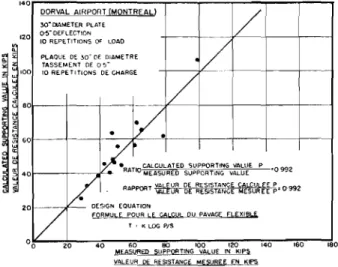
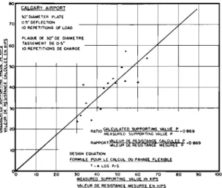
A method of design for the thicknessesof flexible pavement required for aircraft loads on multi-wheel landing gear assemblies is included, by means of which the equivalent single wheel load can also be determined.A comparison is made between measured pavement supporting values versus supporting values calculated on the basis of the design equation, and very good agreement is shown.
For rigid pavement design, a method is presented for calculating the subgrade moduluskb at the surface of any given thickness of granular base, when the subgrade modulus k , for the underlying subgrade is known.
Flexible Pavement Design for Single Wheel and
Multi-Wheel Landing Gear
Sommaire
Se basant sur la formuleT セ logpIS, I'auteur presente des aba-ques destines
a
determiner les epaisseurs de dallage flexible requises lorsque la charge de I'avion est repartie sur des rouesa
pneu unique. Cette communication presenteegalernentune methode de calcul pour determiner lesepaisseursde dallage flexible requises lorsque la charge de I'avion est repartie sur des trains d'atterrissagea
roues multiples. On peut aussi determiner par cette methode la charge equivalente sur une seule roue.La comparaison entre les valeurs mesurees de la resistance du dallage et les valeurs obtenues par les formules proposees montre une bonne correspondance.
Pour Ie calcul des dallages rigides, une methode nouvelle permet de determiner Ie coefficient d'infrastructure kb
a
la surface d'une epaisseur quelconque de fondation granulaire, lorsque Ie coefficient d'infrastructure ksest connu.In a paper for the Second International Conference on Soil Mechanics, an equation for obtaining the thickness of flexible pavement required to carry any wheel load over any subgrade was described (N. W.McLeod, 1948). This design equation has resulted from the analysis of many hundreds of plate bearing tests made on the runways at Canadian airports(N. W.
Me-Leod, 1947, 1947A, 1948, 1948A, 1948B, 1949). The design
equation is:
where T = required thickness of flexible pavement in inches, P = the gross single wheel load in pounds to be carried
on a runway or taxiway,
S = the total measured subgrade support in pounds for the same contact area, deflection (vertical deforma-tion under load), and the number of repetideforma-tions of load that pertain to the design load P,
K = the base course constant, which is an inverse meas-ure of the supporting value of the flexible pave-ment per unit of thickness, and which varies directly with the size of the contact area.
T = Klog PIS .. (I)
For the same contact areas, the load applied to a circular bearing plate on the surface of a paved runway, which causes 0.5 inch deflection after 10 repetitions, appears to correspond closely with the heaviest aeroplane wheel loads that the run-ways at Canadian airports have been supporting in constant service over a period of years. Consequently, this has been adopted as the criterion for the design of flexible pavements for runways for capacity operations.
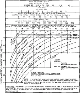
Fig. I is a design chart for required thickness of flexible pave-ments for airport runways for single wheel loads for capacity operations, utilizing Equation(I). The curves designating re-quired thickness for runways are based upon 0.5 inch deflec-tion, while those for taxiways employ a deflection of 0.35 inch. This is roughly equivalent to designing taxiways, aprons, and the turnaround areas at the ends of runways for 20 per cent greater load than runways.
With slight modifications to account for differences in tire pressures where they occur, the runway design curves of Fig. I can be rearranged as shown in Figs. 2 and 3, the tire pressure being 100 p.s.i. for Fig. 2 and 200 p.s.i. for Fig. 3. The curves as shown in Figs. 2 and 3 can be used directly for runway design
'00 '60 セᄋloエャg{オiャcャeャadセl{ャャu R[I;TAN(ilEC(JrjSTITuEPAFlLfS CEI'lTRESャャeセymョrie o{セ ( .. PflEI.. nSOUJuM£LAGE s .O""""".ldQセtahc{ 8[TWU", cゥBLtB{セ Of CO"TA(,T AAf.A5 cs OUAL 'Af\IVE" TlRES '40 5. Ct5TAM'.£ IlfT.,OO[[NCENT"ESo, CQ>olTA(.l"flEAS{)flJuALTIA(S 60 80 100 120 THICKNESS INIfolCHES EPAISSEUR ENーセ 40 20
VALUEOfSUElGl'lAOCSUPPORT IN POlJ,..,CS-30"OIAMtT£RplateMッGA^セdᆪflectQonMiorᆪpetitャons OFlDAD VAUUR DE LA RESISTANCEOU SQUS-SOI. ENLIVR[S-PI.AQUE DEJO" OE DLAMETRE-TASSEMENTDEoGUセ
'0repetitioiiiセ DE alARGE o 8 g 8 8 n 80 :5;;;; 0
g
セ セh ィセ セセ § 0 セセN
/
V ,"w/
セi
1/
1//1/
f/
i
V
V
V I---<VI8-36 ''''''00,
60POOセ..r
. ; ' ecoec セa IA" .-II'..
I"; z セIl
r
"
セLセ
セ
セoesign CURVES FOA SINGLE WHEEL LOADAT 200 PS.lセA
COURSES POUR CHARGE PAR ROUE ISOLEE - PRESSIONnREPRESSURE _ -DEGONfLAGEDES PNEU$:200PS.l, "00セゥ _DCO
$-'Q
d, ..._ CLfAAD'ST,L"CfBETWH1'I CoNl.o(,TAI'lU,$UFO<JALO!l[}UAl TIlI<CEJoITMSa·OIS14/'1C[ INT£R1£UR£ £NTlll. S c.'SUNCf [foiTIlE C£tH'lE:' DE
ャ⦅eBGtセUocspヲッャus sn.nll'fOE5E ....I'<EIJH1.SOl,I JU"£LAGE
t:illlE'"IU'"",",,,, Tt<tCI<NESSDfl'Avrlll[NTAT_'Q<E.ocf< T,,,, OFI)lJ.4LCR(A.rALTAfoIOEIII ....f;EEL ASSEMBU[S
sthesZxセ H'E SU6G$IAD£ ASiii..INOfPENDfJ'Il U"" ,セOR
e .. '_THlCf(f\I[:.SOfP/l.VEME"lATWH'C"OUAL50ROUAlTANli£IoISSTR(SST>if<;u8GRolDfASONe WLATEOS, .. liLf ,., ..HLCAIlRT'''!>'Hl5A1oOt TOTAL LOAD. 25
セセ{セセセseセZセ_セセセセZセGセセrセeセZセGBイeuオセャエZtセセセセeセdZセセp OセセReュウ z EP....SSiuR ..Lセ D£PfiYAGE Alaoueャセe DES 1l0,IfS JUMfLfE5 O'J .UMELEtS l.N rANDEM c.otIlf"R,M(h'll"ffIl.ASTRlJCTuI'lE COMM[ UN£セeulャ "WE 'SOLEr.25
Fig.4 Diagram Illustrating Dimensions of Contact Areas that Control Thicknesses of Pavements at which Dual or Multiple Wheel As-semblies Stress the Subgrade as Independent Units and as one Isolated Single Wheel Carrying the Same Total Load Diagrarnme montrant les dimensions des surfaces de contact sur la base desquelles sont determinees les epaisseurs des reveternents. Montages de roues jumelees ou multiples sollicitant I'infrastruc-ture, soit en tant qu'unitcs independantes, soit en tant que roue unique portant la rnerne charge totale
Fig. 3 Flexible Pavement Design and Evaluation Chart for Single-Wheel and Multiple-Wheel Landing Gear Assemblies (Tire Pressure 200P.S.I.)
Abaques pour determination de l'epaisseur des pistes pour roue unique ou pour roues multiples (pression de gonflage des pneux 200 P.S.I.)
tires or dual tandem wheels to beevaluated. By using a load factor of 1.20, Figs. 2 and 3 can also be employed for the design and evaluation of flexible pavements for taxiways, aprons, and turnarounds for loads applied by either single wheel or multi-wheel landing gear.
The use of Figs. 2 and 3 for runway design and evaluation for multi-wheel landing gear is based upon an approach sug-gested by Boydand Foster(1949), and illustrated by Fig. 4, in which d is the minimum clear distance between the contact areas of dual or dual tandem tires, whiles is the spacing be-tween the centres of the contact areas of dual tires, and the diagonal distance between the centres of the contact areas of dual tandem tires. Studies by Boydand Foster (1949) have indicated thatd/2 is the maximum thickness of pavement at
'00
,..,
'40 V |セセ L.EGENO セ_ _RUNWAYS PIST£S Q'ATTERRISSAGE --TAXIWAYS,ETC PlSTES DE RACCOROOtfNT, ere . / セMM\ 1 <,STRlI TOCRUISER=1=
-+-- T 60 80 100 120 THICKNESS IN INCHES EPAlSS£UREN roUCESi
t.A""" 40 20 'I\lAU£ or SiJ8G,RAOE <;,J"I'l),'lTBQMGojoioGsMセBvャanet{r PLAfl-OS"D[Fl.ECTIOh-IORl.I"£TITIONSQI'LOllI: IlAl..EuR DE L'" "rV',lAN:E ou s.ossc.eセ !1',' .. E<;-·P!.JlQU[:)f !>O"OE DiA/IoIfTFlE-TASSEIllE.NTOf:O!>"
10llEPil,lIUN'S ccCHARC,[
rJ (]":---.'DESIGN CuRvES FOR SINGLE WHEEL LOAD liT 100 PS,1.
セ IJ--i
f1
TIREPRESSURE t--t--t--iセ
r
I
i COUReES POLFl CHARGE PAR ROUE ISOLE£ - PRESSIONI / j I DE GONfLAGE DES PNEUS: 100 PSl
'""0 4POO 40r---fJ'-,'n--
.
d' / セGAゥGPGMMエMBMMKMMKMMMiM/
DESIGNEQUATION FQRMlJL[pqオセle CALCUL O'EPAISSEUB LッイMMセi f+ih'-1<-l,c" T, Ill0G(P/SlrtQll.IN GENERoll,THf VolLUE5 Of CON£ BEARIf\lG,HQUS£L PHlETROM(l[R,
nuccBR "NO "NGlE OF INT£RNALfRienD "I JoIOICATED,'&PPLV TOFINE TElT-WッャMMMMQBMGuijセMT lJR£D COHESIIiE50lLS MD REPFlESEIIITTHE AVfRAliERATI.. o FOA THE TOP:l
EEETOfTH[SUBGR"O[
Fig. 1 Design Curves for Flexible Pavements for Runways and Taxi-ways, etc. for Aeroplane Wheel Loadings (Full Load on Single Tire)
Abaques pour Ie calcul de reveternents flexibles adaptables aux pistes d'atterrissage, de raccordement, etc., la charge par roue de l'avion etant donnee (charge totale sur pneu unique)
REMARQu£ - EN GE"ERlot.lES IIAlEURS DE AE5,5TAfoICf DOfoiNEES P"R LE CONE, LE PENETROMETRE HOUSEl. l:APPARiIL ce« (TセiBBgle DE fRICTlO,* INTEIl'-1:TEL QU'lfoIDIQUE, 5'olPPLIOUE"fT AUJ 50L5 CQHES!F5 DE FI"IE TEXTURE E1 REPRE5ENTEN1 OES VALEUIlSセyeBBGes POuRLE5 OEUXPltOS Suf'EJIIEURS OE 1."NFIlASTAUCTuR[
Fig.2 Flexible Pavement Design and Evaluation Chart for Single-Wheel and Multiple-Wheel Landing Gear Assemblies (Tire Pressure 100P.S.I.)
Abaques pour determination de l'epaisseur des pistes pour roue unique ou pour roues multiples (pression de gonflage des pneus 100 P.S.1. セ livrcs par pouce carre
I\.NGL£ OF INTrR .. A,Hl'CH0N A"GLE or fAL(,JIO" '''HRNf セQ_L_RLP セイ 3?セSU Sセ SセU 4.0 fiELD CEIR LliPPAR['lCBR セ セ 4 5 6 セ ilセ If I,B 2p 2,2 -QQPusセl 'PEN[TR0Mf:TfR NOr»セャuwセ fO" 6 '"CHf',ーヲZBᆪhセatャon - - - 1 P[NfHtOr.<UFll'lOIhEl -"OMBR£ DECOUP;' 1'001'1セᆪ P[Nl HIAT'OND[UGセ eovceS
e 10 1,5 20 2,5セセゥG 40 45 50
イMMMMMMlNMセM CONE IllA"'N!> 1'';,1
VALrUROERESISII\NCEOONNE£PI\RlfCO"EiNLI\lRESpARPOuCE cARRf
'0
'0
or evaluation for isolated single wheel loads. In addition, Figs. 2 and 3 can beemployed for either the evaluation or design of flexible pavements for runways for aircraft with dual tires, dual tandem, or other multi-wheel landing gear. They also enable the single wheel load equivalent to that applied by dual