Publisher’s version / Version de l'éditeur:
ASTM Special Technical Publication, 347, pp. 70-81, 1964-10-01
READ THESE TERMS AND CONDITIONS CAREFULLY BEFORE USING THIS WEBSITE.
https://nrc-publications.canada.ca/eng/copyright
Vous avez des questions? Nous pouvons vous aider. Pour communiquer directement avec un auteur, consultez la première page de la revue dans laquelle son article a été publié afin de trouver ses coordonnées. Si vous n’arrivez pas à les repérer, communiquez avec nous à [email protected].
Questions? Contact the NRC Publications Archive team at
[email protected]. If you wish to email the authors directly, please see the first page of the publication for their contact information.
NRC Publications Archive
Archives des publications du CNRC
This publication could be one of several versions: author’s original, accepted manuscript or the publisher’s version. / La version de cette publication peut être l’une des suivantes : la version prépublication de l’auteur, la version acceptée du manuscrit ou la version de l’éditeur.
For the publisher’s version, please access the DOI link below./ Pour consulter la version de l’éditeur, utilisez le lien DOI ci-dessous.
https://doi.org/10.1520/STP347-EB
Access and use of this website and the material on it are subject to the Terms and Conditions set forth at
Some engineering properties of built-up roofing
Jones, P. M.
https://publications-cnrc.canada.ca/fra/droits
L’accès à ce site Web et l’utilisation de son contenu sont assujettis aux conditions présentées dans le site LISEZ CES CONDITIONS ATTENTIVEMENT AVANT D’UTILISER CE SITE WEB.
NRC Publications Record / Notice d'Archives des publications de CNRC:
https://nrc-publications.canada.ca/eng/view/object/?id=216e3a4c-1a86-4d4c-85ad-fe725493a840 https://publications-cnrc.canada.ca/fra/voir/objet/?id=216e3a4c-1a86-4d4c-85ad-fe725493a840
r 6 c e n t e s a n n g e s p o u r l e s e t u d e s s u r l a r e s i s t a n t r a c t i o n ont kt6 e m p l o y e e s . t e m p e r a t u r e e s t p a s s e e d e 7 5 ° F 'a - 2 0 OF. L e r d l e s e joui: p a r l e b i t u m e a Ct6 c o n f i r m 6 p a r un m e d i o c r e une i a i b l e r e s i s t a n c e k l ' e i i e t d ' e n t a i l l e .
t\utl~orizcd Reprint from t l ~ c Copyrigl~tcd Symposium on Recent Rcscnruh on Bituminous hlaterials
SPeciol T e c l ~ ~ r i r o l P ~ r b l i r a l i n , ~ X o . .?-I?
Publishcrl by thc
4
.:>, &,AMERICAS SOCIETY POX TBSTISC ASD MATERIALS ; $.> -%. 8 , .* . ->
1963 <.t,
-
::' L .., .*.PS O M E E N G I N E E I i I N G P R O P E R T I E S O F BUILT-UP R O O F I N G
The prevalence of splitting in built-up roofing during recent years has prompted special studies to be ullclertaken by the Division of Building Re- search to determine the causes for these serious failures. The deterlnillatioll of certain engilleering properties of the components used in built-up roofing and the complete membrane have received special attention. To cletermille these properties, a roller-coating technique was developed to prepare mem- branes and a special grip arrangement was constructed for the tensile studies. These studies were made at 75 F and a t -20 F, using two rates of straining. The results emphasize the secondary role of the bitumen ill the strength of the membrane. At both temperatures the felts contribute 80 to 90 per celit of the strength of the membrane, although the actual strengths increased by 70 to 250 per cent as the temperature changed from 75 F to -20 F. The small amount of creep and of notch sensitivity also serve to confirm the sec- ondary role of the bitumen.
Some construction components are nonload-bearing and are not normally designed to carry a load. Some of the materials that make u p these compo- nents, however, m a y become strained d u e t o movements of the structural elements or deformations due to temperature a n d moisture changes. A roohng membrane can b e classed as a nonload-bearing ma- terial. I n common with other materials of this class little information is available o n its strength and deformation proper- ties, and the stress-strain properties of the membrane can b e important in de- termining its performance ability.
Recent experience with serious split- ting of built-up roofing membranes be- lieved t o have resulted from cold weather conditions with little snow has raised 1 Organic Matcrinls Section, Division of
Building Research, National ltcscnrch Council, Ottawa, Canada.
cluestions a b o u t the shrinkage and ex- tensibility of roofing materials a t low temperatures a n d has prompted a study of these properties under controlled con- ditions i n the laboratory. Techniques for preparation a n d loading of roof samples had to b e developed a n d these are now reported, together with some of the re- sults obtained for a limited number of materials and temperature conditions.
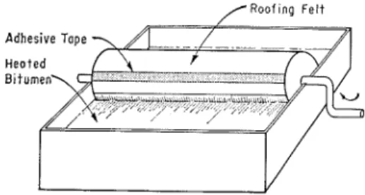
Samples of roofing membranes with uniform applications of bitumen were required for t h e testing program. I t was found t h a t membranes prepared on a roof varied considerably; samples pre- pared o n a small scale using a mopping technique were also thought t o be un- suitable. A simple roller-coating tech- nique was developed which had the added advantage of ensuring that all
portions of the felt were coated with bitumen. The procedure was used in the preparation of samples from two bitu- mens and three types of felts. A com- mercial-grade roofing pitch was used in conjunction with a tar-saturated roofing felt. A commercial-grade, dead-level as- phalt was used with a n asphalt-saturated rag felt and a n asphalt-saturated glass felt. All materials were of good quality, produced by well-known manufacturers, and complied with the requirements of the pertinent specifications of the Ca- nadian Standards A s m 2 T h e asphalt had a softening point of 145 F ; the coal- t a r pitch had a softening point of 140 F. T h e brittle-point characteristic of these
The roller-coating method used rollers 13 in. long and 43 in. in diameter. T h e surfaces and ends of these rollers were covered with a silicone-treated aluminum foil to serve as a release agent. The roller was then wrapped with one turn of roofing felt which was held in place by a piece of adhesive tape applied along the butt joint in the felt. T h e assembly was placed in a bath of heated bitumen (Fig. 1) and rotated, to coat the felt with bitumen. The alnount of bitumen applied in this manner was controlled b y the temperature of the bath and the
.
rate of rotation of t h e roller. A satis- factory rate of application was obtained with a temperature of 430 F when as-/ Roof ~ n g F e l t
L Y
FIG. 1.-Preparation of Ruilt-up Roofing Membrancs.
two bitumens was measured using a modified Fraass test;3 a value of -5 F was obtained for the asphalt, compared with a value of +51 F for the coal-tar pitch.
2 "Asphalt Saturated Roofing Fclt for Usc i n Waterproofing and in Constructing Built-EII Itoofs, 15-lb Typc," AlJd-G (1953); "Asphalt for Use in Constructing Built-Up Itoofing. T y ~ c 1," Al93-7 (1063) ; "Coal-tar Saturated Itoofing Fclt for Use in Wntcrproofing a n d in Constructing Built-Up Itoofs, 15-11, Type,"
11123-8 (1953); "Coal-tar Pitch for Itoofing
Dalnpproofing and Waterproofing, T y p c A,"
A12S-13 (1053); "Asl111alt Saturated Fclted
Glass-Fibre M a t for Use in Co~istruction of Built-UD Roofs Type 1," Al28-17 (1063). Canadian Standards ASSXI., Eastview, Ont., Canada.
3 P. 3.1. Jones, "The Use of a Brittle-Point
T e s t in Low T c ~ n p e r a t u r c Studies 0x1 .4sphalts," Proceedings, Canadian Technical Asphalt Assn., 1963, pp. 15-34.
phalt was used and 320 F when coal-tar pitch was used. It was possible to prepare samples containing about 21 lb of bitu- men per 100 sq ft, well tvithin a range of & I 0 per cent. After the roller was lifted from the bath the felt was removed by stripping back t h e adhesive tape, allowing the felt to fall from the roller, with t h e bitumen side down, onto a flat sheet of aluminum foil coated with a release agent. The felt was then rolled to remove unevenness in bitumen thick ~ n e s s . A second coated felt was then prepared and applied to the first, to achieve a 2-ply membrane. Continuation of this procedure could produce membranes with a n y desired number of plies. Mem- brane samples 2 plies thick and about 12 in. square were obtained in this may for
testing. When the membrane had cooled, T o measure the deformatioil of the samples for tensile studies were cut with specimen during testing, a strain gage a jig and a sharp knife to produce a speci- was used, as shown in Fig. 3. The gage men with the dimeilsions shown in Fig. 2. length of 2 in. is defined by two pins T h e tensioil testing apparatus (Fig. 3) which penetrate to the center of t h e coilsists of a small horizontal tellsometer specimen. Expansion or contraction of
4 in Radius
yoke -\
G r ~ p ~ d a p i o r
FIG. 2.-'l'cnsion Specimen \\it11 Grip .\rrangement.
I:IG. 3.-Tensile Testing ;\pparatus.
n i t h an added motor drive ailtl gear box which eilablcs various rates of straining to be used. The load on the specimen in the tensometer is transmitted to a spring beam, the deflection of which is propor- tional to the loatl. This deflectioil is measured by the movemeilt of a column of mercury in a glass tube.
the specimeil produces a change in t h e distance between the pins which causes movcmeilt of the core of a diflerential transformer. This results in a change of Aux which is recorded in a magnified scale on a recorder. This strain gage is calibrated so that a movement of the sample of 0.0001 in. can be measured.
A
special gripping arrangement had to be designed to hold the specimens in the tension testing apparatus. This was necessary because the nature of the ma- terials made using the conventional serrated grips impossible since they were unable to hold the membrane ~ v i t h o u t movement of the intermediate material. T h e bitumen coating interfered with proper gripping, the intermediate plies had n tendency to slip, and the resultswhich they can be shifted transversely to align the specimen with the line of load application. The yokes are attached to the loading tackle of the tension test- ing apparatus.
T h e amount of coating bituincn h ~ s very little effect on the ~ t r c n g t h of the membrane a n d it is anticipated that a 3- or 4.~157 system urould be propor- tionately stronger than the 2-ply system used throughout this study. The 2-ply
5 Asphalt Gloss Cross
6 Caol - T a r P i t c h Roa Crass 2~ I Aspholf Rog Length
2 Cool-Tar P i t c h Rog Length 3 Asphalt Gloss L e n g t h 4 A s p h a l t Rog Cross
5 Asphalt Gloss Cross
6 Caol - T a r P i t c h Rog Cross 3 M F 2 - P l y F e l t s
M 2 - P l y Membrane
0 0.2 0.4 0 . 6 0 . 8 1.0 1.2 1.4 1.6 1.8 2 . 0 2.2 2.4 S t r o ~ n , per cent
FIG. 4.-Breaking Strengths of Built-up Roofing Testecl a t 75 F at a Itate of 0.050 in. per min.
were generally unsatisfactory with many specimens breaking in the grips. Also, with conventional serrated grips, the geometric axis of the specimen cannot possibly he adjusted to coincide with the axis of load application. T h e grip arrangement finally adopted (Fig. 2). which obviates these problems, employs a commercial wire belt-lacing embedded in the ends of the specimens and then coated with an epoxy cement. T h e belt lacings are attached to specially devised mating adapters bl- steel hinge pins. Thesc adapters are held in yokes in
membranes do not contain any extra bitumen in the form of a flood coat, and when the saturated felts were examined for tensile properties, 2-ply samples were also used. Tensile studies were made on three tj-pes of melnbranes and also on three types of felt without bitumen as an interply adhesive. Specimens were prepared both in the length or machine direction of the felt manufacture a n d across this machine direction. Testing was carried out at two temperatures,
75
a n d - 20 F , and a t two rates of strain,EPPECT OF MEAIDIZAKE quite high with the rag felt samples, b u t ,rhc first series of tests was made a t a sinaller in the case of the glass felts. temperature of 75
F
and a t a straill rate comparisoil of the results for the of 0.050 in. per mill speed. T h e saturated felts with those for the mem- results are show11 in Fig. 1 and a sum- branes sho~ils that the strength of t h eT A B L E 1.-EFFECT 01' 311<1\IBItANlC ON BREAKING S T l t E N W I I S O F BUILT-[;I' ItOOFING.
Saturated Felts hlembranes Samplc Direction Breaking I\reaking Breaking nreaking
Strain, Loa?, lb Strain, Load, lb
per cent per 111. per c e n t per In. . . .
Aspllalt r a g . . crosswise lcngth~visc 0.55 1.45 32 73 1 . 0 3 2 . 3 3 75 40 Aspl~nlt glass. . .
{
lc~lgtllwisc crosswise 1.00 1.00 41 27.5 1 . 4 0 1.70 45 36 Coal-Tar pitch r a g . . . . . ottlwise 1.30 67.5 1 . 771 .SO 37 2 . 4 1 29 M L Membrane L e n g t h Direction F L F e l t s L e n g t h D i r e c t ~ o n M C M e m b r o n e Cross D i r e c t i o n F C F e l t s Cross D i r e c t i o n ZOO 0 V a l u e s a t -20 F n - l B 2 V a l u e s a t 75 F m 0 A rn c .- s 0 w
-
m 100 nAspholt Rag Cool-Tor P l t c h Rog A s p h a l t Gloss
FIG. 5.-Comparison of Breaking Loads of Built-up IZoofing a t 75 F and -20 F. mary of the breaking strengths is pre-
sented in Table 1. T h e tabular values are the average of three determinations; the curves in Fig. 4 are for a typical sample and are actual determined values. I n all cases the strength of the felts is higher in the machine direction than in the cross direction. T h e difference is
membranes is largely the result of the felt strength. The rag felt in the length direction contributes 96 per cent of the strength of the membrane; in the cross direction 81 per cent is contributed by the saturated felt. With glass membranes the saturated felt contributes 80 per cent of the strength in t h e length direction
and 76 per cent in the cross direction. With coal-tar pitch samples, the satu- rated felt contributes 88 per cent of the strength of the membrane in the length direction and 94 per ceiit in the cross direction.
T h e influence of the felt fiber is il- lustrated in Fig. 4. T h e rag felt samples in the length direction exhibit almost identical stress-strain curves and are not greatly modified b y the use of different bitumens. This was also the case for the samples of rag felts in the cross direction, the coal-tar pitch and asphalt-saturated felts having similar properties in this
felts, particularly with the rag samples. The asphalt-rag membrane shows an in- crease in the breaking loacl of the mem- brane of 200 per cent i n the length direc- tion and 250 per ceiit in the cross direction. T h e coal-tar pitch membrane increased in breaking strength 130 per cent in the length direction and 230 per cent in the cross direction. The as- phalt-glass membranes show increases of 'iO per cent in the length direction :
and 50 per cent in the cross direction. The differences between the various types of felt increase a s the temperature is lowered. T h e contribution of the felt
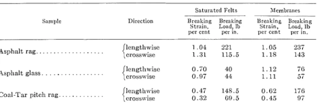
TABLE 2.-BREAICING S T R E N G T H S OF BUILT-UP ROOFING .1T -20 F.
Saturated Felts Xlembraues
Sample Direction Breaking Breaking Breaking Breaking S t m i n , Load! lb Strain, Load, lb per c e n t per in. per cent per in. Asphalt reg Asphalt glass. . . lcngthxvisc 1 . 0 4 221 1 . 0 5 237 crosswise 1.31 115.5 1 . 1 8 143 lcngthwisc 0.70 40 1 . 1 2 76 crosswise 0.97 44 1 . 1 1 57 Coal-Tar pitch r a g . . . . . 0.47 148.5 0 . 6 2 l 7 6 {crosswise 0.32 0 . 5 0 . 4 5 97
respect. The rag felts saturated with coal-tar pitch and asphalt-saturated rag felt, however, were obtained froin cliffer- eiit manufacturers and it ~vould be cs-
pected that the unsaturated rag material is clillerent in each case.
T o determine the elfect of low tem- perature upon the tensile properties of the materials. s ~ e c i m e n s ,
.
were tested a t a temperature of -20 F and a t a strain rate of 0.050 in. per niin. A comparison of the breaking loads a t this temperature with those a t 75 F is shown in Fig. 5, and a summary of the breaking strains and breaking loads is given in Table 2. These results show the large increase in the breaking load of the membranes andstrength to the strength of the mem- brane, however, is proportionately un- changed, with the exception of the glass felts \vhich contribute less to the strength of the membrane. I11 t h e lenrrth dircctioii "
the glass felt contributes only 52 per cent of the loacl and in the cross direction, only 74 per cent. This indicates that t h e strength is to some extent controlled b y the load-carrying capacity of the coating asphalt and t h a t a failure of the asphalt results in failure of the membrane. s o m e evidence of this was noticed during some tests a t slower rates of loading. With asphalt-rag membranes, the asphalt split a t about half the breaking load but, al- though the cracks penetrated to the rag layer, no premature failure was noticed. With t h e asphalt-glass membranes, hotv-
ever, a crack in the asphalt appeared to EFFECT O F 1<.\~1.: OF
result in failure of the sample almost LOAD .\I~I~I~IC.ATION
iinnlediately. Since bitumens are viscoelastic ina- The breaking strains in general de- terials, it be expected that, to the creased as thc temperature was lowered extent that they carry load clirectly,
T A B L E 3.-EFICISCT Ob' IiATIS O F L O X D I S G U P O S STIIISNCTII O F BITILT-KiP I t O O F I S G .
I
1
Tem:iernture: 75 F1
T e m p e r a t u r e : -20 F Asl~halt r a g . . . .(I
r2sl~h:rlt glass. . .(I
Coal-Tar pitch rap
!I
R a t e of L o n d i n g : / ~ a t e of Loading: Rate o f ~ o a d i n g : / ~ a t c ot Loading: 0.050 in. per min 0 001 111. per rnln 0.050 in per rnin 0.001 in. per mi11 llirection -
I '
, -
I
/ Break- Break- / Break-
I
Ilrenk-1
i n g 1 ing)
i n g/
is^S t r a i n , ILoad, lb S t r a i n Load, I t
per c e n t / per in. per ccn't per in.
-- -- - --
i~wgtlnvisa
I
1 . 0 31
:;
1
I . 711
47crosswise 2 . 3 3 3 . 7 7 27
Bleak- Break- 13re;tk- Break-
g ing i n 6 I n /
Strain, Load, lb S t m ~ n , Load, lb
per cent per in. per cent per in.
Legend IR
i Arpnolt Roq Length
2 C o o l - l o r P i t c h Roq ~ h n g t h I S 3 A r p h o t Rog Cross 2 0 0 - n - 4 C o o l - l o r P i t c h Roq Crorr 5 A s p h o t Glorr Length n 6 A r p h o l t Glorr Crass
2 9 R o t e of Srraininq a t 0 . 0 5 0 in. per mi"
c?
5 Rofe of S t r a i n > n g a f 0 . 0 0 i in. per m n
s 3 5 m - I I I I I I 0 0 . 2 0 . 4 0 . 6 0 . 8 1.0 1.2 1.4 1.6 1.8 2 . 0 2 . 2 2.4 2.6 S t r o l n , per cent
FIG. 6.-Efiecl of R a t e of Straining on Breaking Strengths of hlembrancs a t -20 I:.
froin 75
I:
to -20 F . All the asphaltic their contribution to strength would be membranes have allnost idelltical break- varied by changing the rate of straining. ing strains of 1.1 per cent a t -20 F , T o investigate this, tests of the mem- whereas the coal-tar pitch membranes branes were repeated a t the much lower are about 0.5 per cent a t this tempera- straining rate of onl5- 0.001 in. per mi11 ture. head speed. This produced times to fail-ure of 2 to 3 hr. Specimens were tested a t both 75
I:
a n d -20 1; except for the coal-tar pitch samples which were not tcstecl a t 75 F. A summary of the break- ing loads and breaking strains is given in Table 3. I11 Fig. 6 the stress-straincurves for the membranes a t - 20 I: are shown. T h e results in Table 3 show that the lower rate of loading results in lower breaking loads a t 75 I;. Figure 6 clemon- strates that a t -20 1; only a small amount of viscous flow is evident from the slightly lo\ver slope of the stress- strain curve. T h e ultimate breaking strength is unchanged, escept that the
tcn~puraturc have up to 40 per cent less strength than the origitlal uililotched specimens. This relatively small notch sensitivit). tends to conhrm the sec- ondary role oi the coating bitumen in contributing to strength, even at lo\v temperatures when it is quite brittle. These results also tend to minimize t h e ~)ossible importance of brittle failure as a factor leading to splitting of roof mem-
branes. t
D~scussros
The results show t h a t the felt plays a lnajor role in the strength of the inem-
T ~ ~ B L E 1.-EFI;EC:T OF SOTCI~I UPON BItE:lI<II*;G LOAD OF ItOOFING &IEkIBItANICS.
Per Cent Reduction in Breaking Strength Based o n Sample Direction Standard Specimens
A t 7 7 1: A t -?OF Asgllalt r a g . . . . . . . . Asphalt g1:~ss. . . . Co:~l-Tar 11itcli r a g . lcngtl~wisc 0 19 crosswise 0 15
coal-tar pitch samples have a much higher breaking strain a t the lower rate oi straining.
EFFECT OF NOTCIH
T o determine the possible effect of cracks or ilaws in initiating splitting failures as a result of embrittlcment in a n actual roof, a series of notched speci- mens were tested. These were 2 in. wide a n d were notched symmetrically a t the center to produce a net section 1 in. wide. T h e y were tested a t 75 I; and -20 F a t a speed of 0.050 in. per mill head speed. The results, shown in Table 4, indicate that there is no notch sensi- tivity a t room temperature and t h a t , depending upon the bitumen t!.pe of felt used, notched specimens a t the lower
brane. T h e fact that a t - 20
I:
the sam- ples have almost the same tensile propcr- r ties regardless of rate of straining indicatcs that little creep of the bitumen occurs a t this temperature. B u t a t 55I?,
creep would appear to have a n influence since, a t the slow loading, the breaking loads arc sharply decreased while the corresponding strains are increased.
Although it is still difficult to relate the results to the splitting of real roof membranes, i t is of interest to note that, while the breaking strains decreased, t h e strength of the membranes increased with reduction in temperature. It Mias apparent t h a t to begin to assess the strains t h a t might be occurring in real roofs t h e shrinkage due to lowering t h e tempcrature would have to be deter-
mined, for coinparisoil with the strains which the membranes exhibit a t break- ing. Attempts to make such measure- ments and further consideration of them indicated, however, that this was not a simple matter. T h e temperature effects themselves are complicated b y the na- ture of the membrane, which m a y have to be regarded as having three compo- nents: fiber, saturant, and coating. Apparent thermal contraction may there- fore have to be related to load as ~vell as to duration and rate of loading since, in practice, membranes are undoubtedly loaded progressively in tension as they cool and shrink. Another complication is introduced by the presence of water in felts so that dimensional changes upon cooling will be a function of moisture content also. Preliminary experiments indicate that, as a further complication, the shrinkage effects m a y not be linear with temperature b u t may increase a t a greater rate below the freezing point. Measurements of shrinkage are being continued but have not progressed to the point of reporting.
T h e following facts have been shown: 1. T h e breaking load of a rag mem- brane saturated and coated with either asphalt or coal-tar pitch and tested in the length direction is double t h a t of the cross direction.
2. T h e breaking loads of the asphalt- glass membranes are equal in each direc- tion and are roughly the same as those
of the bitumen rag ineillbranes when tested in the cross machine direction.
3. T h e breaking loads of the bitumen- rag membranes were tripled when the temperature was tiecreased from 75 F to -20 F , and over the same range the breaking load of the asphalt-glass mem- branes increased bjr about 70 per cent. 4. T h e breaking strains varied as t h e temperature changed. T h e coal-tar pitch membranes in each direction had a marked decrease in breaking strain from 1.7 per cent a t 75 F t o 0.5 per cent a t - 20 F . T h e asphaltic membranes in t h e cross machine direction decreased from 2.3 per cent a t 75 F to 1.2 per cent a t -20 F for the rag and from 1.7 per cent a t 75 F to 1.1 per cent a t -20 F for t h e glass. T h e asphaltic membranes in the length direction showed little or n o change in breaking strain.
5 . T h e membranes have approxi- mately the same breaking load as the bare felts, indicating t h a t the strength of the roof depends largely upon the strength of felts and that the coating bitumen serves mainly as a waterproofer.
T h e author acknowledges with appre- ciation the advice a n d encouragement given to him by N. 13. Hutcheon, as- sistant director of the Division of Build- ing Research. Appreciation is also clue Mr. G. Quenneville f o r assistance with testing. This paper is a contribution from the Division of Building Research, National Research Council, Canada, and is published with the approval of the Director of the Division.
DISCUSSION
MR. W. H . GUMPERTZ~ AXD E . TOXS.~ ---The author deserves great credit for
the useful contribution he has made in a field where a great deal of off-the-cuff opinions are supported by little concrete knowlege. His work should encourage further fundamental investigation into the physical properties of built-up roofing materials and the mechanical behavior of i t s c o m ~ o n e n t s . For clarification and some questions, we would like to make the following comments, following the outline of the paper:
1. A 2-ply composite built-up roof may be convenient for testing, but it is not realistic. I n a 4-ply specimen with flood coat, the weight percentage of the papcr felt is only about half of that in thc author's test specimens; this propor- tion tcnds to distort the relative effect of the felt and the mopping bitumen on the propertics of the built-up roofing, espc- cially a t low tempcratures.
2. T h e lacing type of attachmcnt may allow somc interply slippage and random variation of test results. I t also makes use of dogbone specimens necessary. Esperiencc indicates that not only will a rectangular specimen be simpler to pre- pare, but no testing difficulties will be encountered if thc ends are anchored with a low-modulus mixture of epoxy resin. (Details of the procedure have
1 Principal, Simpson Gulnpertz & IIeger,
Iric , Cambridge, Mass.
"ssistant Proicssor, Department of Civil Engineering, hIassacbusetts Inst. of Tech- nology, and consulting engineer, Simpson Gumpertz & IIcger, Inc., Cambridge, hlnss.
been developed by the writers and will be published soon.)
3. One statement in the paper is that the '(coating (mopping)" bitumen has very little effect on the strength of the - membrane, and that a 3- or 4-ply system should be proportionately stronger than the 2-ply system. We cannot subscribe to this conclusion since the mopping asphalt, as discussed above, is only a small' part of the total membrane in the author's specimens. Since the paper or fibrous elass felts will not be affected u
substantially by a change in tempera- ture, the steep increase in membrane and felt strength from 75
I:
to -20 F call be explained only by the changing viscoelastic behavior of the bitumens, both as impregnant and as mopping material. At temperatures below freez- ing, the properties of membranes are dominated largely by its impregnant and mopping bitumens.4. T h c author shows a general increase by a factor of 4 in the tensile strength of specimens by dropping the temperature for 75 F to -20 F , except in thc case of glass fibrous felts, where the strength increase is only 1.5- to 2-fold. Tests b y us and by Owcns-Corning Fiberglas Re- search Center seem to indicate that the factor of 4 applies to all types of mem- branes. This seems to correlate with t h e theory t h a t the total bitumen content strongly affects the strength character- istics of all types of mcmbranc at the lower temperatures.
asphalt-glass membrane fails as soon as the asphalt fails may be interpreted in a different way. T h e greater modulus of elasticity of the glass fiber might prevent a visible bitumen failure for some time while the load increases; the cracking of the bitumen occurs near the final failure point in the glass felt.
6. Notch tests made on symmetrical cross-sections appear to have little ad- ditional significance over simple ten- sion tests; the statement about the a1 ure as a importance of the brittle f '1
factor in roof splitting appears to be a non sequitur.
7. T h e author seems to disregard roof movement, and especially differential movement in discrete areas, as a prime cause of roof splitting in winter. So far no evidence has been submitted t h a t would prove that a built-up roofing membrane can pull itself apart because of uniform thermal movements; highly localized strains, due to dimensional changes in the size of underlying cracks or joints in the support have again and again been shown to be responsible for most if not all tensile roofing failures.
8. (See Table 2 of the paper.) T h e increase in strength of glass-fiber mem- brane over that of glass-fiber felts is 30 per ccnt in the transverse direction, b u t 90 per cent in the longitudinal direction. Since the only difference between these ttvo groups is in the mopping asphalt (which is nondirectional), this discrep- ancy suggests a need for additional tests. I t is hoped t h a t these tests will be continued and will be complemented b y others. More should be learned about a1 ure the connection between strength, f '1 strain, and ability of membranes to bridge local cracks.
MR. P
.
M. JONES (autlzor).-Theinterest and critical comments of Messrs. Gumpertz and Tons are appreciated.
I believe. however, t h a t several of the points arc repetitive and so I will not reply to each but \~lill discuss the gen- eral auestions that have been raised.
One of the more important advantages of the 2-ply system is the ease with which interply slippage can be over- come: further studies have indicated that 3- and 4-ply membranes are pro- portionately stronger. T h e use of a flood coat is desirable in service and it ob- viously must be retained in a n y testing of actual roof sections. Except for studies to assess the basic engineering properties of the membrane this addi- tional quantity of bitumen adds little but mass and thickness to the sample.
The use of a lacing attachment elimi- nates slippage of interply material because the grips penetrate through every ply. This is not true of the system which is suggested b y Messrs. Gum- pertz and Tons, and I cannot accept t h e statement t h a t a rectangular specimen nil1 give no testing difficulties; I would anticipate great difficulty with such a specimen a t low temperatures.
The effect of the bitumen in strength considerations appears to be small, b u t is very noticeable in the breaking strains of the membranes and this is sho~vn in Table 2. which indicates that at -20F all asphaltic membranes have the same breaking strain regardless of the nature or fiber direction of thc felt.
Brittleness can be considered as the property of failure trith little or no deformation and, in the case of very brittle materials like glass, failure can be precipitated by a small defect. I t was to determine if this stress sensitivity existed in built-up roofing that the notch test was used. T h e slight decrease in breaking strength was not considered sufficient to enable a roof failure to be triggered by a small flaw or defect.
misinterpreted m y intent when they state that I disregard building move- ment. This paper is intended to give information on the nature of a roof membrane. A knowledge of the limiting stresses and strains for materials used in roof construction would enable design considerations to be given to building movements and to other sources of strain
such as temperature and moisture changes.
The apparent confusing variation in the results of the glass fiber membranes given in Table 2 can be explained b y the splitting of the asphalt coating for i t will be noted that the breaking strain is the same in each direction of the glass membranes.