HAL Id: hal-02170466
https://hal.archives-ouvertes.fr/hal-02170466
Submitted on 1 Jul 2019HAL is a multi-disciplinary open access
archive for the deposit and dissemination of sci-entific research documents, whether they are pub-lished or not. The documents may come from teaching and research institutions in France or abroad, or from public or private research centers.
L’archive ouverte pluridisciplinaire HAL, est destinée au dépôt et à la diffusion de documents scientifiques de niveau recherche, publiés ou non, émanant des établissements d’enseignement et de recherche français ou étrangers, des laboratoires publics ou privés.
Joint range extension and localization for LPWAN
Mohamed Naoufal Mahfoudi, Gayatri Sivadoss, Othmane Bensouda Korachi,
Thierry Turletti, Walid Dabbous
To cite this version:
Mohamed Naoufal Mahfoudi, Gayatri Sivadoss, Othmane Bensouda Korachi, Thierry Turletti, Walid Dabbous. Joint range extension and localization for LPWAN. Internet Technology Letters, Wiley, 2019, �10.1002/itl2.120�. �hal-02170466�
Joint range extension and localization for LPWAN
Mohamed Naoufal Mahfoudi
1| Gayatri Sivadoss
2| Othmane Bensouda Korachi
3|
Thierry Turletti
1| Walid Dabbous
11Université Côte d’Azur, Inria, Sophia
Antipolis, France
2Amadeus S.A.S., Sophia Antipolis, France 3Altitude Infrastructure, Rouen, France
Correspondence
Mohamed Naoufal Mahfoudi, Université Côte d’Azur, Inria, Sophia Antipolis, France.
Email: [email protected]
Funding information
This work was partly funded by the French ANR through the "Investments for the Future" Program under grants
ANR-11-LABX-0031-01 (UCN@Sophia), ANR-10-EQPX-0031-01 (FIT) and ANR-15-IDEX-01 (UCAJEDI).
Summary
This papers introduces Snipe, a novel system offering joint localization and range extensions for LPWANs. Although LPWAN systems such as Long Range (LoRa) are designed to achieve high communication range with low energy consumption, they suffer from fading in obstructed environments with dense multipath components, and their localization system is sub-par in terms of accuracy. In this work, MIMO techniques are leveraged to achieve a higher signal-to-noise ratio at both the end device and the gateway while providing an opportunistic accurate radar-based system for localization with limited additional cost.
KEYWORDS:
LoRa, Spatial filtering, Coherent combining, Angle of Arrival (AoA)
1
INTRODUCTION
Low-power wide-area networks (LPWANs) are sought to be the networks of choice for large-scale Internet of things (IoT) communication in urban areas. Their main selling points are a low power consumption that can span the course of a decade and a large geographical coverage of a few kilometers1. They also offer a cost-effective alternative to their cellular counterparts by operating on the sub-gigahertz ISM band, thus avoiding costly licenses. Unlike cellular networks which give great importance to dimensioning and have adopted industry standards concerning the quality control, privately owned LPWANs suffer from an inherent heterogeneity and poor dimensioning that hinder their performance in terms of rate, or poses serious reliability questions. This paper presents Snipe, a diversity combining LoRa system with spatial filtering techniques providing: (1) an enhanced communication range for end devices and gateways alike and (2) a precise and accurate position estimation system based on radar techniques. By exploiting the multipath effect that is omnipresent in urban and in-building settings, the Snipe gateway can increase the received signal-to-noise ratio (SNR) and hence enhance its decoding capabilities. Moreover, the system uses spatial filtering techniques in order to achieve a higher SNR at the end device. While most contributions are towards improving the uplink2,3, Snipe enhances both the uplink and downlink by using a Multiple-Input Multiple-Output (MIMO) design that respects the LoRa energy consumption restraints. Furthermore, MIMO support at the gateway provides low cost Angle of arrival (AoA) and end device position estimation. By offloading the position estimation processing to the gateway, the Snipe system alleviates the energy cost incurred when using GPS-enabled end devices. Moreover, by hosting the MIMO signal processing locally at the gateway, the proposed system allows combining coherently the signals from each one of the antennas elements indiscriminately. This contrasts with cloud-based approaches that involve renting compute and storage nodes as well as providing links with large bandwidth3.
The rest of the paper is organized as follows: Section 2 reminds some basic LoRa principles. Section 3 presents the range extension problem and the approach to address it by leveraging coherent combining and spatial filtering. Section 4 presents in
0This work has been done while the second and third authors were at Inria Sophia Antipolis.
This article has been accepted for publication and undergone full peer review but has not been through the copyediting, typesetting, pagination and proofreading process which may lead to differences between this version and the Version of Record. Please cite this article as doi: 10.1002/itl2.120
This article is protected by copyright. All rights reserved
Accepted
2 MOHAMED NAOUFAL MAHFOUDIET AL
more detail the AoA estimation technique needed to perform spatial filtering. Section 5 presents the power gain for both the uplink and the downlink. Section 6 describes the related work and Section 7 concludes the paper.
2
LORA PRIMER
Many IoT applications require low cost, low energy and long range communication. Spread spectrum techniques provide enhanced robustness with frequency diversity and low power density with signals transmission below the noise floor. However, classical Direct-sequence spread spectrum (DSSS) systems for IoT applications need highly accurate and expensive reference clock source violating the low cost requirement. LoRa uses Chirp Spread Spectrum, a modulation technique in which chirps are used as carrier signals where information is encoded on. An up (down) chirp is a tone in which frequency increases (decreases) linearly with time. An advantage of this specific spread spectrum technique is that timing and frequency offsets between transmit-ter and receiver are equivalent, which reduces the complexity (and therefore the cost) of the receiver design. Different parametransmit-ters can be used to customize the modulation such as the Bandwidth (BW) and the Spreading factor (SF). The SF is equal to the number of raw information bits per symbol. At the cost of a reduction of bit rate, adopting a higher SF results in higher time on air, which provides a better coverage and a higher packet delivery ratio. LoRa is able to change the SF according to the link quality and different orthogonal SFs can be supported to trade data rate for sensitivity within a fixed channel bandwidth. In the EU863-870 ISM (unlicensed radio spectrum in the Industrial, Scientific and Medical) band, 3 channels of 125 kHz must be supported by any LoRa end device3.
Figure 1 shows a simplified view of the LoRa demodulation process. The frame payload (part a of the figure) is composed of a chirp sequence transmitted with a given SF. Chirps are cyclically shifted and the user information is encoded in a frequency jump (Δ𝑓 ) at the beginning of each chirp. In order to decode this information, the received signal is multiplied by a down chirp sequence with the same length and SF (part b). Then, a Fast Fourier transform (FFT) is applied to the product to provide the encoded information (part c).
FIGURE 1 LoRA demodulation process.
3
LPWAN MIMO RANGE EXTENSION
Obstruction and multi-path propagation can cause severe channel degradation in indoor environments. This may lead to signif-icant reduction of the communication range in the case of in-building LoRa deployments. In these environments, it is therefore important to try increasing the range in both uplink (from end device to gateway) and downlink (from gateway to end device) directions. This will help to widen the coverage and allow cost-effective deployment of these LPWANs. Hopefully, leveraging spatial diversity with MIMO techniques can mitigate the range reduction and gain some dBs.
Concerning the uplink, several state-of-the-art techniques leveraging temporal, frequency or spatial diversity can be envisaged to enhance the SNR. Temporal diversity is not very appropriate in LPWAN networks because it would require a high duty cycle of end devices (supposed to remain low) and increase their energy consumption. Frequency diversity is already well exploited in LoRa with the Chirp Spread Spectrum modulation that allows robust signal decoding. It can also be used to improve the communication range by increasing the SF. However, this will increase the Time on Air and then energy consumption, which is detrimental for the end devices.
In this paper, the proposed approach is to exploit spatial diversity by adding a second antenna at the gateway to intelligently combine the signals received on both antennas in order to increase the SNR at the gateway and therefore the uplink communi-cation range. As for the downlink, the presence of a second antenna allows to beamform the signal to specific end devices, thus improving the downlink range. However, this enhancement requires knowing the AoA of the signal sent by the end device to the gateway in order to point the beam in the direction of the end device.
The use of MIMO techniques makes it possible to provide the gateway with information on the arrival angle of the signal coming from end devices. This additional information may be combined with various information from other sources such as the
This article is protected by copyright. All rights reserved
Accepted
Time delay of arrival (TDoA) to improve the accuracy of the localisation of LoRa devices. Indeed, traditional LoRa localisation techniques based on TDoA lack in precision when multipath is present and rely on complex fine-grained synchronization4.
Regarding leveraging spatial diversity in LPWANs, previous work has proposed combining signals from an end device arriv-ing at several gateways in the cloud in order to improve the SNR and thus increase the range of the uplink. The approach described in this paper, supporting a second antenna at the gateway allows to improve the range in the uplink direction, while saving bandwidth between gateways and the cloud infrastructure. The cost of this approach in terms of CPU and energy con-sumption is reasonable because the addition of the antenna and processing functions takes place only at the gateway which, unlike end devices, does not use a battery but is connected to a power source.
In the rest of the section, the range extension techniques used to enhance the transmission range from the gateway to the end device and vice versa are presented.
3.1
Coherent Combining
The Snipe system takes advantage of the MIMO capabilities at the gateway to increase the SNR and improve the decoding of the received signals. In particular, by leveraging the presence of multiple RF chains and antennas, it is expected to benefit from the diversity factor that comes from the spatial separation of antennas. The rationale is that when the target signal suffers from multipath fading, different copies of the signal can be combined in order to provide a more robust representation of the signal. The system adopts a weighted average approach, where the weights are selected to delay appropriately each copy of the signal to align the different copies (see Figure 2). Thus, the signals are added up constructively as follows:
𝑦𝑐𝑜𝑚𝑏=
𝑁
∑
𝑣=1
ℎ∗𝑘𝑦𝑘 (1)
where 𝑦𝑘is the received signal at the 𝑘𝑡ℎantenna element and ℎ
𝑘is the channel estimate for the 𝑘𝑡ℎantenna. The output 𝑦𝑐𝑜𝑚𝑏is
the summation of 𝑁 matrices.
FIGURE 2 Distorted Chirps in the LoRa signals impinging on the antenna array are combined by aligning, scaling and summing
the different copies producing a signal with a higher SNR.
3.2
Spatial filtering
As presented earlier, Snipe uses beamforming or spatial filtering as a suitable candidate for not only increasing the decoding capabilities of end devices but also for reducing interference between devices. Beamforming allows obtaining a higher gain in the target direction while attenuating other directions without the need for directional antennas. More precisely, by sending simultaneous signals from the different elements of the Transmit RF chain, the omnidirectional radiated signals are combined to form a higher gain beam to a certain direction. In order to exploit this feature, a fine-grained control over the direction of the beam is needed, which is possible by defining complex weights on each one of the RF chains, see Figure 3. By defining weights that control the phases of the radiated signals at the antennas, it is possible to augment the response in a certain direction:
w𝑘= 𝛼𝑘𝑒−𝑗2𝜋(𝑘−1)𝑑 sin 𝜃 (2) z(𝑡) = 𝑁 ∑ 𝑘=0 w𝑘y𝑘(𝑡) (3)
where 𝜃 is the beam steering angle, 𝑑 is the distance between the radiating antennas,𝛼𝑘the signal amplitude weight, 𝑁 is number of antenna elements in the array and 𝑦𝑘is the signal transmitted by the 𝑘𝑡ℎantenna.
Note that the defined weights are related to the position of the target. Thus, it is imperative to accurately estimate the AoA of the signal radiated from the end devices in order to steer the transmitted beam to the direction of the target.
Accepted
4 MOHAMED NAOUFAL MAHFOUDIET AL
FIGURE 3 LoRa signal beamforming by applying complex
weights to each RF chain. This allows combining the signals constructively towards the direction of the target.
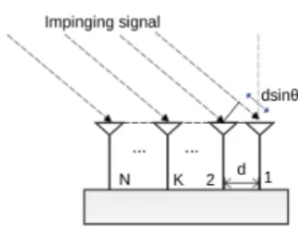
FIGURE 4 Signal impinging on an 𝑁-element uniform linear
antenna array: Each antenna receives a copy of the signal with a phase shift (𝑘 − 1)𝑑 sin 𝜃 relatively to the reference antenna, with 𝑑, the antenna spacing, in the order of half a wavelength.
4
BEAMFORMING AND AOA-BASED LOCALIZATION FOR LORA
The objective is to propose a system that allows continuous tracking of end devices and updating of the steering angle, so it is therefore important to estimate the AoA of a LoRa end device.
In fact, AoA estimation allows tracking the origin of a signal through measuring the signal’s phase from different available positions (spatially separated antennas). Measuring the AoA is based on the observation that the signal of interest impinging on the antennas is received at slightly different time delays, see Figure 4. As the measured baseband signal is represented in the frequency domain, the relative phase is computed between the signals received at the antenna array. This choice is justified by the fact that if a signal incurs a delay in the time domain, it is translated into a phase shift in the frequency domain. This phase shift is completely defined by the distance between the antennas and the direction of arrival of the signal. Usually, this distance is expressed in wavelengths and is kept in the order of half of the wavelength 𝜆. It was shown in a previous work5 that respecting this distance constraint makes it possible to reduce the effect of mutual coupling, which usually occurs when the antennas element of the antenna array are too close (less than 0.2𝜆) and creating side lobes that can potentially pollute the AoA estimations if they are too far (more than 0.5𝜆).
The received signal and the relative phase can be expressed by the following matrix representation:
x= ⎛ ⎜ ⎜ ⎜ ⎜ ⎝ 𝑥0 𝑥1 ⋮ 𝑥𝑁−1 ⎞ ⎟ ⎟ ⎟ ⎟ ⎠ = ⎛ ⎜ ⎜ ⎜ ⎜ ⎝ 𝑎0(𝜃0) 𝑎0(𝜃1) ⋯ 𝑎0(𝜃𝑟−1) 𝑎1(𝜃0) 𝑎1(𝜃1) ⋯ 𝑎1(𝜃𝑟−1) ⋮ ⋮ ⋱ ⋮ 𝑎𝑁−1(𝜃0) 𝑎𝑁−1(𝜃1)⋯ 𝑎𝑁−1(𝜃𝑟−1) ⎞ ⎟ ⎟ ⎟ ⎟ ⎠ ⎛ ⎜ ⎜ ⎜ ⎜ ⎝ 𝑠0 𝑠1 ⋮ 𝑠𝑟−1 ⎞ ⎟ ⎟ ⎟ ⎟ ⎠ + ⎛ ⎜ ⎜ ⎜ ⎜ ⎝ 𝑛0 𝑛1 ⋮ 𝑛𝑁−1 ⎞ ⎟ ⎟ ⎟ ⎟ ⎠ (4)
where 𝑎𝑘(𝜃) = 𝑒−𝑗2𝜋𝑘𝑑𝑠𝑖𝑛(𝜃) represents the phase shift between the signals received by the reference and the 𝑘𝑡ℎ antenna. For
practical reasons, the signal is presented in a compact form:
x=[a(𝜃0) a(𝜃1) ⋯ a(𝜃𝑟−1) ]
⋅ s + n , (5)
x= A⋅ s + n , (6)
where x is the 𝑁 × 1 received signal vector, A is the 𝑁 × 𝑟 steering matrix which columns are the steering vectors a(𝜃𝑘), s is the vector composed of 𝑟 transmitted signal 𝑠𝑘and n is the Gaussian white noise vector with zero mean. Here, lowercase, bold lowercase and bold uppercase denote respectively scalars, vectors and matrices.
The first step of the procedure consists in computing the sample covariance matrix. Usually, time distributed samples (packets) can be used to obtain a robust estimation of the covariance. However, as very few packets are exchanged in the context of LoRa applications, an estimation procedure that involves time-frequency distributed samples is adopted. Choosing such an approach allows taking advantage of the intrinsic diversity of chirp modulated signals. Thus, the sample covariance matrix is computed from the IQ samples corresponding to 𝐿 observations in time ̂𝐑𝐱𝐱 =
1
𝐿
∑𝑁 𝑖=1𝐱𝐱
𝐻. Then, the eigenvectors and eigenvalues of
the 𝐑𝐱𝐱is computed by performing an eigen-decomposition, where 𝐑𝐱𝐱= 𝐐𝐃𝐐𝐻. Based on the assumption that the signal and
noise vectors are uncorrelated, the 𝐐 matrix containing the eigenvectors is partitioned into two subspaces, one spanned by the signal eigenvectors 𝐐𝑠corresponding to the largest eigenvalues and the other by the noise eigenvectors 𝐐𝑛. Then the MUSIC algorithm6is used to estimate the parameters by launching a search over all the possible values of the steering vectors to identify the ones related to the signal. This is possible because, as mentioned earlier, the signal and noise are uncorrelated and thus the signal steering vectors are orthogonal to the noise eigenvectors and ultimately the noise subspace. Finally, the pseudospectrum is computed from the quadratic function,
𝐏(𝜃𝑖, 𝜙𝑖) =
1
𝐚(𝜃𝑖)𝐻 𝐐𝑛𝐐𝐻𝑛 𝐚(𝜃𝑖)
(7)
This article is protected by copyright. All rights reserved
Accepted
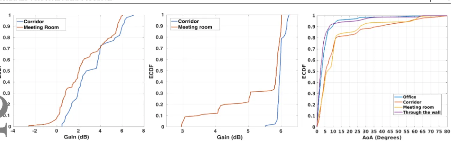
FIGURE 5 ECDF power gain with
beam-forming.
FIGURE 6 ECDF power gain with
coher-ent combining.
FIGURE 7 ECDF of the AoA estimation
error.
where (.)𝐻 denotes the Hermitian operation. The estimated AoA corresponds therefore to peaks in the computed spectrum.
By estimating the AoA for each one of the received signals, it is possible to adapt the radiation pattern and the direction of the lobe. This allows the gateway to track a client when there is a change in the environment or in the position of the client device. In order to achieve a better estimation of the signal source position, a calibration procedure is mandatory in most of the cases where the different RF chains of a transceiver are not synchronized. Indeed, during the frequency tuning phase, each one of the RF chain will lock at different phase offsets if they do not share the same phase reference. This is mainly mitigated by the calibration process where the phase delay between the reference RF chain and the others is estimated using a reference signal coming from a waveform generator with known properties, and applying a phase delay on the RF chains according to the reference RF chain7.
5
SYSTEM EVALUATION
In order to test the system performance, the localization precision and the power gain are both evaluated in a 625𝑚2 office environment. Both the end device and the proposed MIMO gateway are built as custom software-defined radio systems using GnuRadio and Ettus Research USRP B210 software-defined radio on laptops with 32GB RAM and a 2.70GHz i7-4800MQ processor. The MIMO gateway is equipped with a 2-element ULA (VERT 900MHz) for beamforming and a similar ULA for AoA estimation and coherent combining, while the end device has only one antenna for transmission and another one for reception. Two channels were established between the gateway and the end device: the uplink on the 900 MHz frequency and the downlink on the 868MHz frequency. A band-pass filter with a bandwidth of 4MHz for the 869MHz frequency that covers the band of interest is used to filter out-of-band interference.
5.1
Beamforming and Coherent Combining effect on Power Gain
To evaluate the gain in power achieved by the system, several experiments were deployed in corridors (with a max dimension of 25m x 1.5m) and meeting rooms (with a max dimension of 9m x 5m) environment. In Figure 5, the Empirical CDF (ECDF) shows the power gain in both environments when using beamforming. An average power gain of 2.7 dB in the corridor environment and 2.0 dB in the meeting room is observed in comparison to omnidirectional radiation patterns. The performance difference comes from the partial or total occlusion between the gateway and the end devices when experimenting on through-the-wall transmission.
The coherent combining technique was evaluated in the same environments. Figure 6 shows the result of coherent combining of the signals impinging of the 2-element antenna array. An average power gain in the meeting room and the corridor of 5.81 dB and 5.99 dB respectively is observed in comparison to single antenna setups. Indeed, by applying the coherent combining technique, it is possible to enhance the downlink between the gateway and the end device. Roughly the same power gain is retained across environments and conditions, i.e., Line-of-sight (LOS) and Non-line-of-sight (NLOS).
5.2
Position estimation precision
In order to test the precision of the AoA estimation for the localization and beamforming purposes, both were tested against different environments. Figure 7 shows the ECDF of the AoA estimation error. Theb mean error in the office environment is 4.84◦. This is explained by the relatively short distance between the gateway and the end device, as the maximum distance between the transceivers is 12 meters. Regarding the corridor and meeting room environments, the mean error is 12.1◦and 11.2◦ respectively. A drop in AoA accuracy is observed mainly due to the estimation algorithm (MUSIC) that tends to suffer from the correlation between the multipath and the LOS signals. In fact, the longer the distance between the transceivers, the bigger the number of reflected signals and thus, the higher the estimation error. However, the error is still relatively small, thanks to the
Accepted
6 MOHAMED NAOUFAL MAHFOUDIET AL
estimation process that samples the signal in time and frequency. Finally in the case of through-the-wall position estimation, the mean AoA error is 4.66◦, which can be explained by the limited distance between the transmitter and receiver. Basically, the LOS signal is attenuated but not occluded and the effect of reflected signal on the wall is negligible.
6
RELATED WORK
LoRa range extension has been the focus of multiple research projects trying to increase the decoding capabilities at the gateway level for the uplink, while achieving a low power consumption by end devices2,3. A system with a single antenna gateway that enables collaboration between end devices was proposed to overcome the challenges rising in high density deployment2. However this system requires a dense deployment of end devices and a synchronization mechanism between them. The latter system has been extended by the authors in Charm3, aiming to enhance the battery life of client devices and the uplink coverage of LPWANs in a large urban deployment. The system is built in such a way that if the signal is decodable at any individual gateway, then these weak signals coming from multiple gateways are coherently combined in the cloud. However this approach is only suitable for private operators as it involves costs to maintain a cloud infrastructure and deploying geographically distributed gateways. In comparison, the Snipe system proposed in this paper uses multiple antennas on a single gateway system with the goal of extending the LPWAN range for both the uplink and downlink transmissions. In fact, signals coming from multiple antennas are combined in the uplink communication, which increases the SNR of the signal and at the same time improves the downlink communication through beamforming8,9based on the target signal’s direction of arrival. Regarding localization, the Snipe system based on the estimation of the AoA using super-resolution methods (MUSIC) has proven to be efficient for localization in indoor settings. In comparison, recently a LoRa AoA localization system based on a time-modulated array has been proposed but it was evaluated with a strong LOS and practically no multipath10.
7
CONCLUSION AND FUTURE WORK
This paper presents a novel MIMO-LPWAN system that not only extends the range between a gateway and an end device but also enables a precise LoRa end devices localization system. Indeed, it is shown that leveraging spatial filtering techniques and coherent combining across the signal impinging on a linear antenna array, it is possible to increase the decoding capabilities at both the gateway and the end device. Furthermore, this paper also shows that it is possible to achieve higher accuracy position estimation by adapting model-based MIMO radar techniques to leverage the signal distribution across time and frequency. Future work seeks to enhance the localization accuracy using maximum likelihood estimation techniques that are immune to multipath effects.
References
1. Raza U. et al. Low Power Wide Area Networks: An Overview. IEEE COMST,. 2017;19(2):855-873.
2. Eletreby R. et al. Empowering Low-Power Wide Area Networks in Urban Settings:309–321. ACM SIGCOMM,2017. 3. Dongare A., Narayanan R., Gadre A., et al. Charm: Exploiting Geographical Diversity Through Coherent Combining in
Low-power Wide-area Networks:60–71. IEEE IPSN,2018.
4. Fargas B.C., Petersen M.N. GPS-free Geolocation using LoRa in Low-Power WANs:1-6. IEEE GIoTS,2017. 5. Hannan P. The Element-Gain Paradox for a Phased-Array Antenna. IEEE TAP. 1964;12(4):423-433.
6. Schmidt R. Multiple emitter location and signal parameter estimation. IEEE TAP. 1986;34(3):276-280.
7. Research Ettus. Synchronization and MIMO Capability with USRP Devices.. https://kb.ettus.com/Synchronization_and_ MIMO_Capability_with_USRP_Devices. Accessed June 12, 2019; 2016.
8. Van Veen B.D., Buckley K.M. Beamforming: a versatile approach to spatial filtering. IEEE ASSP. 1988;5(2):4–24. 9. Golbon-Haghighi M.H. Beamforming in Wireless Networks.ch. 8, :163-192. IntechOpen 2016.
10. Baik K.-J., Lee S., Jang B.-J. Hybrid RSSI-AoA Positioning System with Single Time-Modulated Array Receiver for LoRa IoT:1133-1136. 2018.
This article is protected by copyright. All rights reserved