HAL Id: hal-02369085
https://hal.archives-ouvertes.fr/hal-02369085
Submitted on 18 Nov 2019
HAL is a multi-disciplinary open access
archive for the deposit and dissemination of
sci-entific research documents, whether they are
pub-lished or not. The documents may come from
teaching and research institutions in France or
abroad, or from public or private research centers.
L’archive ouverte pluridisciplinaire HAL, est
destinée au dépôt et à la diffusion de documents
scientifiques de niveau recherche, publiés ou non,
émanant des établissements d’enseignement et de
recherche français ou étrangers, des laboratoires
publics ou privés.
Development of Analytical Formulae to determine the
Response of Submerged Composite Plates subjected to
Underwater Explosion
Ye Pyae Sone Oo, Herve Le Sourne, Olivier Dorival
To cite this version:
Ye Pyae Sone Oo, Herve Le Sourne, Olivier Dorival. Development of Analytical Formulae to
deter-mine the Response of Submerged Composite Plates subjected to Underwater Explosion. The 14th
International Symposium on Practical Design of Ships and Other Floating Structures - PRADS 2019,
Sep 2019, Yokohama, Japan. �hal-02369085�
Response of Submerged Composite Plates subjected to
Underwater Explosion
*Ye Pyae Sone Oo1 [0000-0001-7106-6013], Hervé Le Sourne2 and Olivier Dorival3 1 GeM Institute (UMR CNRS 6183) – Calcul-Meca, Nantes, France
2 GeM Institute (UMR CNRS 6183) – ICAM Nantes, France 3 Clément Ader Institute (FRE CNRS 3687) – ICAM Toulouse, France
*ye-pyae.sone-oo@icam.fr
Abstract. Closed-form analytical formulae are developed to analyze the
bend-ing response of submerged composite rectangular plates subjected to underwa-ter explosions (UNDEX). These explosions are supposed to occur at a suffi-ciently large stand-off distance so that a uniformly distributed pressure pulse can be applied and the corresponding bubble effects can be ignored. The plate is considered in an air-backed condition. The derivation steps are divided into two main stages. In the first stage, the impulsive velocity due to the interaction of shock wave and structure is determined by using Taylor’s fluid-structure inter-action (FSI) formulation while supposing a negligible structural deformation. Transmission of shock waves through the thickness of the plate is considered by assuming the material under uniaxial strain. At the end of the first stage, cavita-tion is supposed to occur all over the plate. In the second stage, deformacavita-tion of the plate will commence which is followed by the collapse of the cavitation zone. The corresponding mechanical response of the plate is determined by im-posing a simply-supported boundary conditions and by applying Lagrangian Energy approach to derive the motion equation, taking into account the water inertial effects. The proposed method is then tested with isotropic (steel) and laminated composite (carbon-fiber/epoxy) plates to analyze for both impulsive velocity and UNDEX responses. The obtained analytical results are compared with those from non-linear finite element explicit code, LS-DYNA. Finally, the advantages and limitations of the present method are evaluated.
Keywords: Underwater Explosion (UNDEX), Fluid-Structure Interaction
1
Introduction
During recent years, composites have been widely used in the fields of civil and mili-tary naval structures due to their advantages over conventional materials such as steel. However, there is still a major concern about how these composite structures will respond when subjected to an intense dynamic loading such as underwater explosion or hydrodynamic impacts. These loadings are usually comprised of complicated phys-ical phenomena such as shock wave propagation, fluid-structure interaction, cavita-tion, and so on. In order to capture all these phenomena accurately, one needs to use complex non-linear finite element codes such as LS-DYNA/USA. Nevertheless, this numerical approach is not only very complicated to set up but can also take a lot of computation time. It is, thus, not well-suited for the preliminary design phases espe-cially when solutions with rapid and reasonable accuracy are only desired. In this context, this research is intended to solve the issue by introducing simplified analyti-cal formulae to predict the response of submerged composite rectangular plates to a reasonable accuracy when subjected to underwater explosive loads. The primary ob-jective is to propose various design solutions for the preliminary design of subma-rines, surface ships and fast composite boats. The application area will concern with the underwater shock loadings applied to the composite surface ship sonar domes, submarine acoustic windows as well as hydrodynamic impacts to the composite hulls. The analytical formulations will be developed by assuming that explosion occurs at a sufficiently large stand-off distance so that planar pressure pulse can be considered and the influence of bubble shock waves can be ignored. The calculation steps will involve two main stages. Stage I, which is the fluid-structure interaction phase, will include determination of the impulsive velocity due to the interaction of the shock waves with the structure by using Taylor FSI formulation [1]. The plate is considered to be in an air-backed condition. The deformation of the plate is assumed to be negli-gibly small during Stage I. Transmission of the shock waves throughout the thickness of the plate is taken into account by assuming the material under uniaxial strain. In Stage II, the mechanical response of the plate is determined by imposing a simply-supported boundary condition and by applying Lagrangian Energy approach to derive the equation of motion, accounting for the water-added inertial effects. Closed-form analytical solutions will be proposed at the end. The developed formulations are first tested with steel to check their validity. Only then, they are applied to a more compli-cated case of composite plates. The predicted results for both materials are compared with those from non-linear finite element explicit code, LS-DYNA. Finally, the accu-racy as well as limitations of the proposed method will be evaluated.
2
Literature Review
Underwater explosion has long been the focus of naval research since World War I and II. The majority of these extensive researches has been published through three volumes of ‘Underwater Explosion Research’ issued by the office of Naval Research in 1950 [2]. Cole [3] also systematically presented some of the useful summaries regarding the physical effects of UNDEX. A general literature review about the noticeable worldwide research efforts in the fields of blast loaded marine structures can be found in Porfiri and Gupta [4].
Experimental works dealing with underwater explosion can be divided into two: one testing with real explosive facilities and the other using laboratory environment. In the past, experiments of the former type were mostly performed. For example, in the 1980s, experimental shock tests were conducted on a large number of glass-reinforced plastic (GRP) composite panels and a full-scaled midship section to deter-mine suitable materials for the newly-built deter-mine hunter [5]. During the 1990s, a series of underwater explosive tests were performed on GRP composite laminates by Mouritz [6-9] in order to analyze the damage response behavior of stitched or non-stitched GRP laminates, fatigue properties, flexural strength, and so on. Arora et al. [10] have conducted full-scale experimental studies on glass-fiber reinforced polymer (GFRP) and carbon-fiber reinforced polymer (CFRP) sandwich composite panels and laminate tubes when they are subjected to air and underwater blast loadings. A Dyno-Crusher test, an alternative way of studying a 1D response of multi-layered pyramidal core sandwich panel due to the water blast, can be found in Wadley [11,12].
The experimental tests mentioned above are only concerned with the use of real explosives on the test samples. However, these tests are usually expensive, time-consuming and involve extensive safety measures. Therefore, shock tests using lab-scaled environment are getting more popular in the recent years. In those experiments, a projectile impact-based shock tube is widely employed. It typically consists of a gas reservoir, a high-speed camera, a projectile, a long water-filled shock tube, a thin piston plate and a test specimen. This kind of apparatus was initially used by Desh-pande et al. [13] who studied the effect of underwater shock loading on the structures and proved the finding of Taylor [1]. Later it was modified by Espinosa [14] by de-signing a divergent shock tube to overcome the dimensional limitation imposed by the apparatus size. Schiffer and Tagarielli [15] used a transparent shock tube in order to observe not only the dynamic response of circular composite plates but also the cavi-tation effect. LeBlanc and Shukla [16-18] studied UNDEX response of composite plates and curved composite panels by detonating an explosive charge at one end of a water-filled conical shock tube. From 2012 to 2017, a series of papers were published regarding the use of Underwater Shock Loading Simulator by Avachat and Zhou [19-23] to investigate the shock response behavior of laminated composite plates and sandwich structures. Qu et al. [24] also employed the same apparatus to analyze the dynamic response of thick- and thin-walled composite cylinders. A recent paper of Huang [25] investigated the dynamic response and failure of composite circular lami-nates by employing a lab-scaled underwater explosive simulator and the 3D Digital Image Correlation (DIC) technique.
With more development in computation power, numerical solutions have been widely employed in the fields of UNDEX and FSI problems. The most common approaches include the use of hydrocodes and Doubly Asymptotic Approximations (DAA)/Boundary Element Method (BEM) codes. Mair [26] gives a fairly comprehen-sive literature review about the use of various hydrocodes to predict the UNDEX responses. Analysis using DAA code uses boundary element method developed by Geers [27, 28]. Its application in the numerical analysis can be found in Underwater Shock Analysis (USA) program. The main advantage of using such method is that the governing equations are expressed in terms of the wet surface variables only and thus, there is no need to model explicitly the surrounding fluid. Applications of LS-DYNA/USA can be found in DeRuntz [29] and Le Sourne et al. [30].
Analytical works regarding the response of composite structures subjected to UNDEX are not very common. One of the earliest theoretical works includes Taylor [1] who proposed a 1D FSI solution to analyze the response of a free-standing rigid plate with an infinite length impacted by a plane shock wave. Librescu [31] proposed an analytical approach based on 3D elasticity theory in the Lagrangian description to study the dynamic response of anisotropic sandwich flat panels subjected to underwa-ter and in-air explosions. In Liu and Young [32], Taylor’s air-backed FSI model was extended to a water-backed model by introducing a new FSI parameter and then solv-ing the governsolv-ing equations to give pressure, velocity and displacement. Wang et al. [33] has provided a novel solution method based on state space methodology, a numerical inversion of the Laplace transform, to yield the elastic dynamic response of the laminated composite plates subjected to UNDEX. A theoretical model that could take into account the stretching forces, transverse shear deformation effect, flexural wave propagation and cavitation induced non-linearity effect has been developed by Schiffer and Tagarielli [34]. Hoo Fatt and Sirivolu [35] presented an analytical meth-od by coupling Taylor’s 1D FSI formulation with the Lagrange’s equation of motion and then by expanding the displacement terms into double Fourier Series to describe the in- and out-of-plane deflections of the sandwich facesheets. Recently, Sone Oo et al. [36], has proposed a simplified analytical solution to predict the elastic response of the isotropic circular plate subjected to air and underwater blasts. Equations of mo-tions are derived based on Lagrangian Energy approach and the time-varying water-added mass term is predicted using Kirchhoff’s Retarded Potential Formulae (RPF) along with a constant averaging term.
3
Analytical Model
3.1 Problem Formulation
Consider a simply-supported rectangular composite plate having the sides 𝑎, 𝑏 and constant thickness ℎ. A standard Cartesian coordinate (𝑥, 𝑦, 𝑧) system is defined at the origin and mid-surface of the plate as shown in Fig. 1. The displacements in the 𝑥, 𝑦, 𝑧 directions are denoted as 𝑢, 𝑣, and 𝑤 respectively. Suppose that the plate has 𝑁 ortho-tropic plies that are bonded together perfectly. The orthoortho-tropic axes of material sym-metry of an individual ply do not necessarily need to coincide with the 𝑥, 𝑦, 𝑧 axes of
Fig. 1. Panel geometry and coordinate system of the problem
the plate. Kirchhoff’s thin plate theory is considered in this paper and hence, the thickness ℎ of the plate is much smaller than the other physical dimensions. In-plane displacements 𝑢 and 𝑣 are assumed negligibly small as compared with the out-of-plane displacement 𝑤. The bending strains are assumed infinitesimally small so that each ply obeys linear stress-strain relationship. In the model presented in this paper, any transverse shear deformation effects are ignored. Also damage and failure is not addressed within the scope of this paper.
3.2 Underwater Blast Loading
The pressure submitted to the plate due to underwater explosion can be near-field or far-field depending on the stand-off distance. The treatment on the compressibility of water and of several other important parameters will be different depending on whether the explosion is near-field and far-field. In this paper, it is assumed that the plate is located at a sufficiently far distance from the explosive source point so that a uniformly distributed planar pressure pulse can be applied. The corresponding bubble effects are ignored in accordance with the far-field assumption. Then, the response due to the aforementioned pressure loading can be calculated in two stages. Stage I, which is the early-time FSI phase, is one in which the maximum impulsive velocity of the plate due to the shock wave is determined by employing the procedures described in [1] and [3] and by assuming a negligible plate deformation. At the end of the Stage I, cavitation is supposed to occur close to the plate. Then comes the Stage II in which the deformation of the plate commences. The corresponding mechanical response of the plate is determined by adapting Lagrangian Energy approach. Water added mass is derived by using the natural frequency for the rectangular plate with water on one side as provided by [37]. It should, however, be aware that during Stage II, no more incident pressure loading is considered. According to the long-time response, only the water added mass effect will be considered in this Stage. The calculation and deriva-tion steps in this paper are indeed analogous to the analytical soluderiva-tions presented in [36] except that [36] considered only fundamental mode shape of vibration.
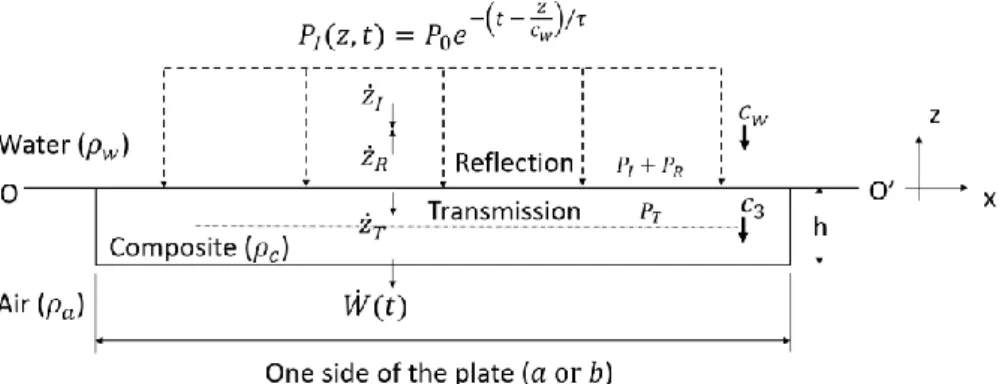
Stage I: Early-time Fluid-Structure Interaction Response. Suppose that a plane
shock exponentially decaying pressure pulse 𝑃𝐼 is submitted onto the composite
rec-tangular plate of density 𝜌𝑐. The plate is in contact with water of density 𝜌𝑤 on one
side and air 𝜌𝑎 on the other side. Note that the incident pressure pulse 𝑃𝐼 is a 1D
shock wave propagating in negative 𝑧 direction at sonic speed in water 𝑐𝑤, as depicted
in Fig. 2. For any arbitrary time 𝑡 and at any arbitrary distance 𝑧 from the fluid-structure boundary OO′, the incident pressure 𝑃𝐼 can be written as:
𝑃𝐼(𝑧, 𝑡) = 𝑃0𝑒 −(𝑡 − 𝑧
𝑐𝑤) 𝜏⁄ (1)
where 𝑃0 is the peak pressure and 𝜏 is the decay time. Both quantities can be
de-termined by applying the principle of similarity, which states that the pressure and other properties of the shock wave will be the same if the scales of length and time are varied by the same scale factor [3]. However, in this paper, both quantities 𝑃0 and 𝜏
will only be defined arbitrarily in order to test the accuracy of the proposed formulae. In Fig. 2, it can be seen that the problem is treated as a single degree of freedom (DOF) and hence, only transverse displacements are considered in the analysis. Any tangential components of velocity for both particles and plate are assumed to vanish. The particle velocities for incident, reflected and transmitted wave are denoted as 𝑧̇𝐼,
𝑧̇𝑅 and 𝑧̇𝑇 respectively and the plate velocity as 𝑊̇(𝑡). Recall that during Stage I of
the response, the plate is assumed to behave like a free-standing rigid plate with neg-ligible deformation. Upon arrival of the shock wave at the FSI boundary OO′, the entire plate will respond with a high frequency, creating rarefaction waves during the process. Some portion of the incident pressure is reflected back into the fluid while the other part is transmitted through the plate depending on the mechanical impedance of the plate material. For composite, the mechanical impedance 𝑍𝑐 can be written as:
𝑍𝑐 = 𝜌𝑐𝑐3 (2)
where 𝑐3 is the through-thickness wave speed in the transverse direction.
Accord-ing to Abrate [38], 𝑐3 can be calculated as:
𝑐3= √
𝐸33(1−𝜈12𝜈21)
Λ𝜌𝑐 (3)
where Λ = 1 − 𝜈12𝜈21− 𝜈23𝜈32− 𝜈31𝜈13− 2𝜈12𝜈23𝜈31.
At the FSI boundary OO′ (𝑧 = 0), the incident pressure is:
𝑃𝐼(𝑡) = 𝑃0𝑒−t 𝜏⁄ (4)
Let us describe the reflected pressure as:
𝑃𝑅(𝑡) = 𝑃0𝜑(𝑡) (5)
where 𝜑(𝑡) is a temporal function to be determined. Note that 𝜑(𝑡) will decay with time and is indeed a component of the reflection and radiated waves due to the trans-verse movement of the plate 𝑊̇(𝑡). Considering the incident wave, reflected wave,
transmitted wave and plate velocity shown in Fig. 2, the velocity continuity equation at the boundary OO′ can be written as follows:
𝑧̇𝐼(𝑡) – 𝑧̇𝑅(𝑡) = 𝑊̇(𝑡) + 𝑧̇𝑇(𝑡) (6)
Then assuming that the fluid density and propagation velocity do not change signif-icantly from the undisturbed values and also supposing sufficiently small disturb-ances, the pressure and particle velocities in the waves can be related by the following equations, according to [3]: 𝑧̇𝐼= 𝑃𝐼 𝜌𝑤𝑐𝑤 𝑧̇𝑅= 𝑃𝑅 𝜌𝑤𝑐𝑤 𝑧̇𝑇= 𝑃𝑇 𝜌𝑐𝑐3 (7)
where 𝑃𝐼, 𝑃𝑅 and 𝑃𝑇 are incident, reflected and transmitted pressure respectively.
The transmitted pressure 𝑃𝑇 can be given in terms of the incident pressure 𝑃𝐼 as:
𝑃𝑇 = 2𝜌𝑐𝑐3
𝜌𝑐𝑐3+𝜌𝑤𝑐𝑤𝑃𝐼 (8)
By substituting Eq. (7) and (8) into Eq. (6), the following equation for 𝜑(𝑡) can be obtained: 𝜑(𝑡) = 1 𝑃0(𝜇𝑃0𝑒 −𝑡/𝜏− 𝜌 𝑤𝑐𝑤𝑊̇) (9) where 𝜇 =𝜌𝑐𝑐3−𝜌𝑤𝑐𝑤
𝜌𝑐𝑐3+𝜌𝑤𝑐𝑤 is the reflection parameter.
Now the total pressure 𝑃(𝑡) applied to the plate can be expressed by summing Eq. (4) and (5) as follows:
𝑃(𝑡) = (1 + 𝜇)𝑃0𝑒−𝑡/𝜏− 𝜌𝑤𝑐𝑤𝑊̇ (10)
With the use of Eq. (10), the following equation of motion for Stage I is obtained: 𝜌𝑐ℎ𝑊̈(𝑡) + 𝜌𝑤𝑐𝑤𝑊̇(𝑡) = (1 + 𝜇)𝑃0𝑒−𝑡/𝜏 (11)
where 𝑊̇(𝑡) and 𝑊̈(𝑡) represent velocity and acceleration of the plate. Analytical solution of Eq. (11) has already been proposed by Taylor [1] in which the maximum impulsive velocity of the plate is given as:
𝑣𝑖𝑚𝑝=
(1+𝜇)𝜉𝑃0𝜏
𝜌𝑐ℎ (12)
Recall that at the end of the Stage I, cavitation is supposed to occur all over the plate. Assuming fluid cavitation pressure to be zero, the cavitation inception time or the peak response time can be determined as:
𝑡𝑐= 𝑙𝑛𝜓
𝜓−1𝜏 (13)
where 𝜉 = 𝜓−
𝜓
𝜓−1 is the momentum reduction parameter and 𝜓 =𝜌𝑤𝑐𝑤𝜏
𝜌𝑐ℎ is the
Fig. 2. Pressure and particle velocity at the fluid-structure boundary
Stage II: Mechanical Response of the Submerged Composite Plate. As discussed
before, the plate deformation is supposed to commence in the second stage of the response. The maximum impulsive velocity obtained at the end of the first stage is applied as an initial condition for Stage II. The incident pressure field is assumed to have vanished completely and the associated plate deceleration causes collapse of the cavitation zone, promoting the water-added inertia. The equation of motion for the plate can be derived by adapting Lagrangian Energy approach and then by describing the out-of-plane displacement term 𝑤(𝑥, 𝑦, 𝑡) in the form of double Fourier summa-tion as:
𝑤(𝑥, 𝑦, 𝑡) = ∑∞𝑖=1∑∞𝑗=1𝑊𝑖𝑗(𝑡)𝜙𝑖𝑗(𝑥, 𝑦) (14)
where 𝑊𝑖𝑗(𝑡) is the temporal term for the modal participation and 𝜙𝑖𝑗(𝑥, 𝑦) is the
spatial term that accounts for the mode shape. Assuming that the plate is simply-supported on all four edges, the mode shapes that would satisfy the corresponding boundary conditions can be given as:
𝜙𝑖𝑗(𝑥, 𝑦) = sin ( 𝑖𝜋𝑥
𝑎) sin ( 𝑖𝜋𝑦
𝑏 ) (15)
where 𝑖 and 𝑗 represent the mode number in x- and y- direction respectively. It must be noticed that the mode shape equation given in Eq. (15) satisfies the following orthogonality relation:
∬ 𝜌𝜙Ω 𝑖𝑗𝜙𝑚𝑛𝑑Ω = 0, for i, j ≠ m, n (16)
where Ω is the area of the plate considered. In accordance with the Eq. (16), all the equations of motion are uncoupled. Later this property will also be applied in the derivation of initial conditions for each uncoupled modal equation.
According to the classical plate theory, only bending of the orthotropic plate is considered. Hence, the expression for the bending strain energy can be given as a form of modal summation using the following equation:
𝑈 =1 2∑ ∑ 𝐾𝑖𝑗𝑊𝑖𝑗 2 ∞ 𝑗=1 ∞ 𝑖=1 𝐾𝑖𝑗 = 𝜋4 4𝑎3𝑏3[𝐷11(bi) 4+ 2(abij)2(𝐷 21+ 2𝐷66) + 𝐷22(aj)4] (17)
where 𝐾𝑖𝑗 is the stiffness term for each mode, 𝐷𝑚𝑛 = 1 3∑ 𝑄̅𝑚𝑛|𝑘(𝑧𝑘 3− 𝑧 𝑘−13 ) 𝑁 𝑘=1 is
the bending stiffness matrix for composite, 𝑁 is the number of layers in the laminate, and 𝑄̅𝑚𝑛|𝑘 is the reduced stiffness matrix for each 𝑘th layer. These matrices can be
readily found in any classical composite literature, for example, see [39]. Similarly, the kinetic energy 𝑇 can be derived as:
𝑇 =1 2∑ ∑ 𝑀𝑖𝑗𝑊̇𝑖𝑗 2 ∞ 𝑗=1 ∞ 𝑖=1 𝑀𝑖𝑗 = 𝜌𝑐𝜋2 12𝑎𝑏∑ (𝑧𝑘 3− 𝑧 𝑘−13 ) 𝑁 𝑘=1 [(𝑎𝑗)2+ (𝑏𝑖)2] + 𝜌𝑐ℎ𝑎𝑏 4 (18)
where the first term in the expression of 𝑀𝑖𝑗 corresponds to the rotatory inertia
ef-fect and the second term to mass inertia efef-fect.
Equations (17) and (18) are finally solved in general Lagrangian Equation:
𝑑 𝑑𝑡( 𝜕𝐿 𝜕𝑊̇𝑖𝑗) − ( 𝜕𝐿 𝜕𝑊𝑖𝑗) = 𝑄𝑖𝑗 (19)
where 𝐿 = 𝑇 − 𝑈 and 𝑄𝑖𝑗 is the non-conservative force function for each mode due
to the external load. Since the current solution portrays the UNDEX response as a free vibration problem, any 𝑄𝑖𝑗 term will be equal to zero. By solving Eq. (19), the
follow-ing equation of motion can be derived:
𝑀𝑖𝑗𝑊̈𝑖𝑗(𝑡) + 𝐾𝑖𝑗𝑊𝑖𝑗(𝑡) = 0 (20)
Note that Eq. (20) is valid only for AIRBLAST or impulsive velocity responses. In order to include the water-added inertia term, Eq. (20) must be modified into:
(𝑀𝑖𝑗+ 𝑀𝑎𝑖𝑗)𝑊̈𝑖𝑗(𝑡) + 𝐾𝑖𝑗𝑊𝑖𝑗(𝑡) = 0 (21)
where 𝑀𝑎𝑖𝑗 is the water-added inertia term and can be calculated by using wetted
natural frequency of the submerged plate given by Greenspon [37], 𝑀𝑎𝑖𝑗 =
𝜌𝑤𝑙
2𝜌𝑐ℎ𝛽𝛼𝑖𝑗𝑀𝑖𝑗 (22)
where 𝑙 is the longer side of the plate, 𝛽 = 𝑓(𝑎
𝑏) is a correction term for various
as-pect ratios of the plate, 𝛼𝑖𝑗 is a correction term for boundary conditions and mode
shapes. The term 𝛽 is bounded between 0 and 1 for 𝑎/𝑏 = 0 and 𝑎/𝑏 = 1 respec-tively. For intermediate values of 𝑎/𝑏, 𝛽 can be expressed as a polynomial function:
𝛽 = 1.5 (𝑎 𝑏) 3 − 3.12 (𝑎 𝑏) 2 + 2.6 (𝑎 𝑏) + 0.0098 (23)
When applying Eq. (23), it should be noted that 𝑏 = 𝑙 is the longer side of the plate so that 0 < 𝑎/𝑏 < 1.
The modal term 𝛼𝑖𝑗 can be determined by using: 𝛼𝑖𝑗= (∫ ∫ 𝜙𝑖𝑗𝑑𝑥𝑑𝑦 𝑏 0 𝑎 0 ) 2 (𝑎𝑏 ∫ ∫ 𝜙𝑖𝑗2𝑑𝑥𝑑𝑦 𝑏 0 𝑎 0 ) ⁄ (24)
The initial conditions for each mode 𝑖 and 𝑗 can be derived by using the initial im-pulsive velocity calculated from Stage I and the orthogonality of the mode shapes. By differentiating Eq. (14), the transverse velocity of the plate can be written as:
𝑤̇(𝑥, 𝑦, 0) = ∑∞𝑖=1∑∞𝑗=1𝑊̇𝑖𝑗(0)𝜙𝑖𝑗(𝑥, 𝑦) (25)
By multiplying Eq. (25) by 𝜙𝑚𝑛(𝑥, 𝑦) on both sides and then integrating over the
surface area, only one term will remain on right-hand side of the equation by virtue of the orthogonality property. Knowing that 𝑤̇(𝑥, 𝑦, 0) = 𝑣𝑖𝑚𝑝 at the initial condition,
the equations for initial conditions become:
𝑊𝑖𝑗(0) = 0 and 𝑊̇𝑖𝑗(0) = 𝐴𝑖𝑗𝑣𝑖𝑚𝑝 (26) where 𝐴𝑖𝑗 = (∫ ∫ 𝜙𝑖𝑗𝑑𝑥𝑑𝑦 𝑏 0 𝑎 0 ) (∫ ∫ 𝜙𝑖𝑗 2𝑑𝑥𝑑𝑦 𝑏 0 𝑎 0 )
⁄ is the correction term for any odd number modes. 𝐴𝑖𝑗 will be zero for any even number modes due to the fact that
the loading and the deformation are axisymmetric.
Finally, analytical solution can be given in terms of modal participation and natural frequency as: 𝑊𝑖𝑗(𝑡) = 𝐴𝑖𝑗𝑣𝑖𝑚𝑝 𝜔𝑖𝑗 𝑠𝑖𝑛 𝜔𝑖𝑗𝑡 (27) where 𝜔𝑖𝑗= √ 𝐾𝑖𝑗
Mij+𝑀𝑎𝑖𝑗 is the wetted natural frequency. Note that when 𝑀𝑎𝑖𝑗 = 0,
the response is simply analogous to that of AIRBLAST or impulsive velocity.
4
Numerical Models
Numerical simulations are performed in LS-DYNA, a non-linear finite element ex-plicit code. Two types of numerical simulations are studied. The first type concerns with the impulsive velocity response in which only 2D finite element plate was mod-elled. The second type includes both fluid and plate models. Detailed modelling steps are provided in the subsequent sections.
4.1 Materials
Two types of material models, steel and CFRP/epoxy laminate, are considered. However, the same geometry of the plate is used for both models. A hypothetical square plate with the dimensions of 203.2 mm and an overall constant thickness of
Table 1. Characteristics of material 1 (steel)
Item Values Units
Density ρ 7822.8 kgm-3
Young modulus E 207 GPa
Poisson ratio υ 0.3
Yield stress σy 545 MPa
Table 2. Characteristics of material 2 (carbon-fiber/epoxy laminate)
Item Values Units
Density ρc 1548 kgm-3
Young modulus E11 137.67 GPa
Young modulus E22 = E33 8.98 GPa
Shear modulus G12 3.66 GPa
Shear modulus G231 162 GPa
Shear modulus G312 183 GPa
Poisson ratio υ12 = υ13 0.281
Poisson ratio υ23 0.385
Tensile strength XT 2214 MPa
Compressive strength XC 1030 MPa
Tensile strength YT 47.5 MPa
Compressive strength YC 80.7 MPa
Shear strength SC 25.6 MPa
6.12 mm is constructed. Therefore, the aspect ratio of the plate ℎ/𝑎 is about 0.03. Material characteristics for isotropic material (steel) are given in Table 1.
As for the composite, a laminated carbon-fiber/epoxy plate with the layout [±45/0/0/0 /±45/0/0/0/90/90/0]𝑆 is considered. Each ply is unidirectional and
has the thickness of 0.278 mm. For ±45 degree plies, each one will have about 0.139 mm thickness so that overall thickness of the laminate is about 6.12 mm.
To make sure that the material shows only the bending response, the out-of-plane shear stiffness, that is, 𝐺23 and 𝐺31, is artificially increased to 50 times that of the
actual values. This has been done just to make sure that the analytical results are comparable to the numerical one, keeping in mind that the out-of-plane shear defor-mation will need to be coupled into the formulation in the near future. Material char-acteristics for composite laminate is given in Table 2.
1 Out-of-plane shear stiffness G
23 increased by 50 times (original value = 3.24 GPa)
2 Out-of-plane shear stiffness G
4.2 Details of the Finite Element Models
Models using only Impulsive Velocity. The finite element model for the plate is
comprised of 2D shell elements. For steel, Belytschko-Tsay element formulation is applied. Material model for steel uses *MAT_PIECEWISE_LINEAR_PLASTICITY without taking into account the strain rate effect. Five through-thickness integration points are considered. A shear correction factor of 0.83 is applied to correct zero trac-tion conditrac-tions at the top and bottom surfaces of the shell.
Regarding the composite plate model, fully integrated shell elements are employed. With *PART_COMPOSITE card, the thickness and orientation of each ply can be defined. A total of 22 through-thickness integration points is used, each representing one laminate ply. The author has performed various sensitivity analyses regarding through-thickness integration points and concluded that there is not much influence. However, the simulation time could be affected a lot and thus, it is decided that one integration point for each layer is sufficient for the desired accuracy. A laminated shell theory is applied by setting LAMSHT=1 to correct for the differences in the elastic constants from ply to ply. The material model for the composite uses *MAT_ENHANCED_COMPOSITE_DAMAGE. However, within the scope of this paper, the problem will be limited to only elastic response without having any dam-age.
Simply-supported boundary conditions are imposed at edges of the plate for both material models. However, due to the symmetry of the problem, only a quarter of the plate has been modeled and the symmetric plane is defined through *BOUNDARY_SPC card in LS-DYNA. As explained above, modelling with the impulsive velocity requires neither pressure loading nor fluid elements. Only impul-sive velocity is applied on the nodes of the plate model as an initial condition. The amplitude of the initial velocity is limited to small values so that materials remain in an elastic regime without suffering any damage.
Models including Fluid-structure Interaction. The fluid is modeled using acoustic
solid element formulation in LS-DYNA employing acoustic material (𝜌𝑤=1025 kgm-3, 𝑐𝑤=1500 m𝑠−1). These elements are similar to the Eulerian
ele-ments since only the nodes attached to the Lagrangian eleele-ments are allowed to move. The length of the fluid model needs to be selected very carefully in order not to have very long computation time as well as the returning wave effects that could come back from the far end of the fluid boundary. In this paper, the effect of varying the fluid column length is analyzed too. The mesh size of the fluid element is chosen as 1 mm in the thickness direction (negative z-direction). This fluid mesh size needs to be fine enough in order to accurately capture the shock wave propagation and cavi-tation behavior, satisfying the criterion 2𝜌𝑤𝑡𝑤< 5𝜌𝑠𝑡𝑠 where 𝑡𝑤 and 𝑡𝑠 are the
thick-ness of the fluid element and structure respectively. The nodes of the structure and the fluid are shared so that fluid-structure coupling is automatically treated in LS-DYNA. The lateral surfaces of the fluid elements are constrained in the x- and y-directions to ensure 1D wave propagation. Cavitation is considered in the analysis by activating the
Fig. 3. Typical finite element model of the rectangular plate: (a) with impulsive velocity and (b)
with acoustic fluid elements
cavitation flag so that when the pressure becomes negative, it will be forced to ze-ro. Numerical damping (BETA=0.25) is applied on the acoustic fluid element for the stability issue. As a consequence, the peak pressure will become slightly less and the decay time slightly long. However, analyzing the impulse at the nearest element to the plate shows that the results are in good accordance with the transferred impulse value provided by Taylor’s formations. A typical finite element quarter plate model with or without the fluid elements are shown in Fig. 3.
4.3 Details of the Finite Element Analyses Performed
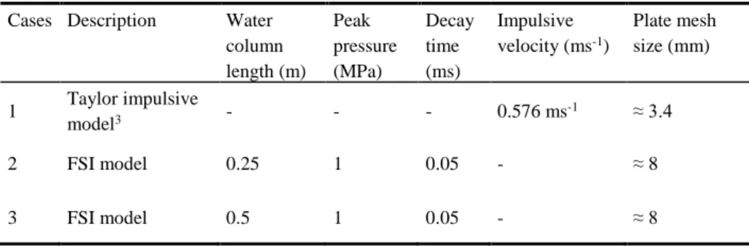
In Table 3 and Table 4, various numerical simulations performed using steel and carbon-fiber/epoxy laminate are shown respectively. The purpose is to analyze the effect of changing the mesh size. Here, it should be noticed that case 1 (steel) and case 4 (composite) contain only shell elements since these cases correspond to impul-sive velocity simulations. On contrary, cases 2, 3, 5 and 6 are simulations with fluid models. As explained in the previous section, it is very important to use the correct length of the water column. It needs to be sufficiently long in order to avoid the re-turning pressure wave reflected from the free end of the fluid column. Therefore, in cases 2 and 3, the length of the fluid (water) column is varied from 0.25 m to 0.5 m respectively to be able to check if there is the returning wave effect. Note that the calculation time becomes almost doubled due to the increased number of solid ele-ments. The size of the plate mesh is kept the same in those two cases. On the other hand, in cases 5 and 6, the effect of varying the plate mesh is studied by using 2 mm and 8 mm mesh size respectively. The tested plate mesh sizes are given in the last column of Table 3 and Table 4. It should also be aware that for composites, the im-pulsive velocity and applied loading is decreased by about 3 and 4 times respectively to guarantee that the response of the plate remains in elastic region.
Table 3. Numerical simulations performed in LS-DYNA (steel)
Cases Description Water column length (m) Peak pressure (MPa) Decay time (ms) Impulsive velocity (ms-1) Plate mesh size (mm) 1 Taylor impulsive model3 - - - 0.576 ms -1 ≈ 3.4 2 FSI model 0.25 1 0.05 - ≈ 8 3 FSI model 0.5 1 0.05 - ≈ 8
Table 4. Numerical simulations performed in LS-DYNA (carbon-fiber/epoxy laminate)
Cases Description Water column length (m) Peak pressure (MPa) Decay time (ms) Impulsive velocity (ms-1) Plate mesh size (mm) 4 Taylor impulsive model - - - 0.182 ms -1 ≈ 8 5 FSI model 0.25 0.25 0.05 - ≈ 2 6 FSI model 0.25 0.25 0.05 - ≈ 8
5
Results & Discussion
The current analytical formulations can be applied to steel by imposing 𝐸11= 𝐸22=
𝐸, 𝜈12= 𝜈23= 𝜈13= ν and 𝐺12= 𝐺23= 𝐺13= 𝐸
2(1+𝜈). The rest of the formulation
will be the same except that the composite density 𝜌𝑐 is replaced by steel density 𝜌𝑠.
The purpose is to check the validity of the current formulation before directly solving for more complex cases of composite. Only after the result of isotropic material is verified, the formulations are applied to investigate the UNDEX response of compo-site plate.
5.1 Response of Isotropic Rectangular Plate
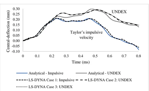
The central-deflection time histories of the steel rectangular plate subjected to Tay-lor’s impulsive velocity as well as water blast loading are shown in Fig. 4 along with
3 Modelling using Taylor impulsive velocity does not require fluid elements. Hence no
infor-mation regarding water column length, peak pressure or decay time is available. Only the in-itial impulsive velocity value is given.
the LS-DYNA results. Based on these results, many important observations can be made. First of all, it can be observed that the present formulations work very well (with 1% discrepancy) for the AIRBLAST response in which only impulsive velocity is modelled. As for UNDEX, added mass inertia term becomes important especially for longer time step. As can be seen in Fig. 4, the response might be seriously under-estimated (about 30%) without the water-added mass. The two plots of LS-DYNA (Case 2 and 3) are overlapped. This means that either using water column length of 0.25 m or 0.5 m does not matter since the results are exactly the same. The analytical result of UNDEX is also similar to finite element results except that the response is slightly faster in the analytical. This is mainly due to the two stage approximations in the analytical calculations. Recall that added mass term could begin only after the end of Stage I. In numerical solutions, added mass inertia might have already evolved since Stage I because the consideration of negligibly small deformation during Stage I of analytical calculation is in fact too idealized assumption. As a consequence, there is slightly more added mass term, leading to slightly longer response (also slightly high-er strain enhigh-ergy) in the numhigh-erical results. In Fig. 5, normalized Von-Mises stress spa-tial distribution is plotted with respect to normalized x-coordinates and then compared with the finite element solutions. It can be seen that present analytical results overes-timate the peak by about 25%. But it is not surprising given the fact that the current analytical solution considers only bending. Other modes of deformation, for example, transverse shear or stretching or both are not negligible in the numerical results.
5.2 Response of Composite Rectangular Plate
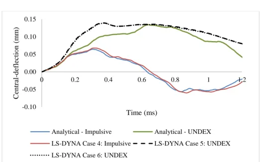
The results of the composite rectangular plate are shown in Fig. 6 and Fig. 7. It can be seen that the current solution predicts very well for the impulsive velocity response since the discrepancy does not exceed 6% and the profiles of the time history curves are very similar. However, there is an obvious difference in the two curves of UNDEX response between analytical and LS-DYNA although the peak amplitude shows only 4% difference. The peak response time in LS-DYNA is obviously faster than that of analytical one. This effect might come from the non-linearity of cavita-tion. Consideration of the through-thickness wave speed could also reduce the im-pulse transferred to the composite plate. Perhaps modelling using 2D shell elements in LS-DYNA may not consider this kind of effect, resulting higher response within a shorter period. This issue still needs to be investigated more in the future. The LS-DYNA results shown in Fig. 6 and Fig. 7 for case 5 (fine mesh) and case 6 (coarse mesh) are very similar, meaning that the convergence of the results has been reached.
Evaluating the stress results in the material direction (𝜎11) for the lowest ply (45
deg) gives satisfactory results as can be seen in Fig. 7 although the numerical results clearly show more damped behavior. It is not surprising, however, because the present analytical solution describes the problem as free vibration response and therefore, there is no damping or compressibility of the fluid.
5.3 Advantages and Limitations
Table 5 (a) compares the time needed to finish one calculation and % discrepancies
of the central-deflection calculated in all the analysis cases are shown in Table 5 (b). The closed-form solutions are implemented in MATLAB (version R2015a). It can be seen in Table 5 (a) that the present approach takes little or almost no time to finish the calculations as compared with LS-DYNA numerical approach. In fact, this much time is necessary in order to store the calculated data for each modal result at each time step. Anyway, it is obvious that adapting analytical approach could improve the cal-culation time by as much as 1857 times as shown in the last column of Table 5 (a). Of course, it depends on how much elements have been used in the numerical model. It is also worth noticing that the calculation time for both analytical and numerical ap-proaches increases for cases 4, 5 and 6. This is normal since cases 4, 5 and 6 represent composite plate and so, requiring storage for the additional variables and of course, more calculation time.
According to Table 5 (b), the proposed analytical approach shows discrepancy less than 10 % compared to LS-DYNA results. It also provides more physical insights into the complicated problem such as underwater explosion.
However, some drawbacks must be pointed out too. One of these is the ignorance of the transverse shear deformation. With the knowledge that transverse shear defor-mation could decrease the natural frequency of the plate, the actual response of the composite plate would be longer than what has been predicted by the current analyti-cal method and the amplitude may be lower. Another drawback of the solution is the consideration of two calculation stages. As discussed before, the action of cavitation is in reality non-linear and depends on a lot of factors such as plate aspect ratio, load duration time as well as the material or orientation considered. That is why some numerical approach such as DAA considers early-time and long-time responses with a smooth transition between the two. The current analytical method simply does not consider this phenomenon and so there is no smooth transition between the two steps. This could be improved by coupling DAA method into the analytical model in which the pressure and structural equations are solved simultaneously for each time step. Table 5. Comparison of the simulation time and the accuracy between LS-DYNA and present
analytical method
(a) Simulation time (sec) (b) Central-deflection (mm) Case LS-DYNA Analytical Faster by Case LS-DYNA Analytical %
1 24 0.2 120 1 0.212 0.209 -1% 2 199 0.25 796 2 0.292 0.3 3% 3 363 0.25 1452 3 0.291 0.3 3% 4 47 1.9 25 4 0.068 0.064 -6% 5 3547 1.91 1857 5 0.139 0.134 -4% 6 277 1.91 145 6 0.139 0.134 -4%
Fig. 4. Response of isotropic rectangular plate (Central-deflection Vs Time; 𝑎 = 𝑏 = 0.2032 m; ℎ = 6.12 mm; First and third terms in Fourier Series 𝑖 = 𝑗 = 1, 3; Taylor’s impulsive velocity response: 𝑣𝑖𝑚𝑝 = 0.576 ms-1; UNDEX: 𝑃0= 1 MPa, 𝜏 = 0.05 ms)
Fig. 5. Spatial distribution of the normalized Von-mises stress (𝜎𝑉𝑀/𝜎𝑌) for the bottom plane
with respect to normalized coordinates (𝑥/𝑎) at the time of the maximum UNDEX response (𝑡max analytical = 0.495 ms, 𝑡max LS-DYNA = 0.514 ms; WC = water column length)
-0.10 -0.05 0.00 0.05 0.10 0.15 0.20 0.25 0.30 0 0.1 0.2 0.3 0.4 0.5 0.6 0.7 0.8 C en tr al -d ef lectio n ( m m ) Time (ms)
Analytical - Impulsive Analytical - UNDEX LS-DYNA Case 1: Impulsive LS-DYNA Case 2: UNDEX LS-DYNA Case 3: UNDEX
0 0.02 0.04 0.06 0.08 0.1 0.12 0.14 0.16 0.18 0.2 0 0.2 0.4 0.6 0.8 1 No rm alize d Vo n -m is es str ess ( σvm /σy )
Normalized x-coordinates (x/a)
Analytical - UNDEX LS-DYNA Case 2: UNDEX (WC=0.25m) LS-DYNA Case 3: UNDEX (WC=0.5m) UNDEX Taylor’s impulsive velocity
Fig. 6. Response of composite rectangular plate (Central-deflection Vs Time; a = b = 0.2032 m;
h = 6.12 mm; First and third terms in Fourier Series 𝑖 = 𝑗 = 1, 3; Taylor’s impulsive velocity response: 𝑣𝑖𝑚𝑝 = 0.182 ms-1; UNDEX: 𝑃0= 0.25 MPa, 𝜏 = 0.05 ms)
Fig. 7. Response of composite rectangular plate (𝜎11Vs Time; a = b = 0.2032 m; h = 6.12 mm;
First and third terms in Fourier Series 𝑖 = 𝑗 = 1, 3; At bottom ply 45 deg; UNDEX: 𝑃0=
0.25 MPa, 𝜏 = 0.05 ms) -0.10 -0.05 0.00 0.05 0.10 0.15 0 0.2 0.4 0.6 0.8 1 1.2 C en tr al -d ef lectio n ( m m ) Time (ms)
Analytical - Impulsive Analytical - UNDEX LS-DYNA Case 4: Impulsive LS-DYNA Case 5: UNDEX LS-DYNA Case 6: UNDEX
-15 -10 -5 0 5 10 15 20 0.00 0.25 0.50 0.75 1.00 1.25 1.50 σ11 (MP a) Time (ms) Analytical - UNDEX LS-DYNA Case 5: UNDEX LS-DYNA Case 6: UNDEX
6
Conclusion & Future Works
This paper presented simplified analytical formulae by adapting Lagrangian Energy approach and Taylor’s 1D FSI method. Results are analyzed for two different types of material models; isotropic rectangular plate and carbon-fiber/epoxy laminated plate. However, only the elastic perturbation of the problem has been focused since the main interest of this research is mainly to find an analytical solution for composite UNDEX response. Using steel material in this case should, in fact, be seen as a trial case before actually applying to more complicated composite cases. Comparisons of the results with LS-DYNA show that the current formulations could predict the max-imum central deflection with a discrepancy less than 10%. The stresses are also cap-tured quite well, only showing 13% discrepancy.
However, it must be kept in mind that this solution considers only bending and so, as long as the plate aspect ratio remains in the correct range, it would be valid. Test-ing with different aspect ratios as well as varyTest-ing loadTest-ing levels still need to be per-formed. Also, it is of practical interest to couple the transverse shear deformation effect into the current approach. Moreover, the authors intend to develop analytical formulations for the water-backed plate. Extending the current formulae for the stiff-ened or curved plate cases would also be interesting. All of these mentioned above will be for future work and the corresponding results will be published elsewhere. Finally, degradation of the strength due to damage will be investigated by adapting some classical failure criteria and then by decreasing the elastic moduli of the plies.
Acknowledgement. This research work has been conducted with the financial
sup-port of DGA-DGE. The authors would also like to thank Calcul-Meca and Multiplast companies for their technical support.
References
1. Taylor, G. I. The pressure and impulse of submarine explosion waves on plates. in The Scientific Papers of G. I. Taylor, Vol. III 287–303. Cambridge University Press (1941). 2. Office of Naval Research. Underwater Explosion Research: a compendium of British and
American reports, Vol. I, II, III. Dept. of the Navy, Washington, D.C (1950). 3. Cole, R. H. Underwater explosions. Princeton University Press (1948).
4. Porfiri, M. & Gupta, N. A review of research on impulsive loading of marine composites. Major Accomplishments in Composite Materials and Sandwich Structures: An Anthology of ONR Sponsored Research. 169–194 (2009). doi: 10.1007/978-90-481-3141-9_8 5. Hall, D. J. Examination of the effects of underwater blasts on sandwich composite
struc-tures. Composite Structure. 11, 101–120 (1989). doi: 10.1016/0263-8223(89)90063-9 6. Mouritz, A. P., Saunders, D. S. & Buckley, S. The damage and failure of GRP laminates
by underwater explosion shock loading. Composites 25, 431–437 (1994). doi: 10.1016/0010-4361(94)90099-X
7. Mouritz, A. P. The damage to stitched GRP laminates by underwater explosion shock loading. Composite Science and Technology 55, 365–374 (1995). doi: 10.1016/0266-3538(95)00122-0
8. Mouritz, A. P. The effect of underwater explosion shock loading on the fatigue behaviour of GRP laminates. Composite Papers 26, 3–9 (1995). doi: 10.1016/0010-4361(95)00030-F 9. Mouritz, A. P. The effect of underwater explosion shock loading on the flexural properties
of GRP laminates. Int. J. Impact Eng. 18, 129–139 (1996). doi: 10.1016/0734-743X(95)00034-8
10. Arora, H., Hooper, P. A. & Dear, J. P. Blast Loading of Sandwich Structures and Compo-site Tubes. in Dynamic Failure of CompoCompo-site and Sandwich Structures. Solid Mechanics and Its Applications (eds. Abrate, S., Castanié, B. & Rajapakse, Y. D. S.) 47–92. Springer, Netherlands. (2013). doi: 10.1007/978-94-007-5329-7
11. Wei, Z., Dharmasena, K. P., Wadley, H. N. G. & Evans, A. G. Analysis and interpretation of a test for characterizing the response of sandwich panels to water blast. Int. J. Impact Eng. 34, 1602–1618 (2007). doi: 10.1016/j.ijimpeng.2006.09.091
12. Wadley, H. et al. Compressive response of multilayered pyramidal lattices during under-water shock loading. Int. J. Impact Eng. 35, 1102–1114 (2008). doi: 10.1016/j.ijimpeng.2007.06.009
13. Deshpande, V. S., Heaver, A. & Fleck, N. A. An underwater shock simulator. in Proceed-ings of the Royal Society A 1021–1041 (2006). doi: 10.1098/rspa.2005.1604
14. Espinosa, H. D., Lee, S. & Moldovan, N. A Novel Fluid Structure Interaction Experiment to Investigate Deformation of Structural Elements Subjected to Impulsive Loading. Exp. Mech. 46, 805–824 (2006). doi: 10.1007/s11340-006-0296-7
15. Schiffer, A. & Tagarielli, V. L. The response of circular composite plates to underwater blast: Experiments and modelling. J. Fluids Struct. 52, 130–144 (2015). doi: 10.1016/j.jfluidstructs.2014.10.009
16. LeBlanc, J. & Shukla, A. Dynamic response and damage evolution in composite materials subjected to underwater explosive loading: An experimental and computational study. Compos. Struct. 92, 2421–2430 (2010). doi: 10.1016/j.compstruct.2010.02.017
17. LeBlanc, J. & Shukla, A. Dynamic response of curved composite panels to underwater ex-plosive loading: Experimental and computational comparisons. Compos. Struct. 93, 3072– 3081 (2011). doi: 10.1016/j.compstruct.2011.04.017
18. LeBlanc, J. & Shukla, A. Underwater explosion response of curved composite plates. Compos. Struct. 134, 716–725 (2015). doi: 10.1016/j.compstruct.2015.08.117
19. Avachat, S. & Zhou, M. Effect of Facesheet Thickness on Dynamic Response of Compo-site Sandwich Plates to Underwater Impulsive Loading. Exp. Mech. 52, 83–93 (2012). doi: 10.1007/s11340-011-9538-4
20. Avachat, S. & Zhou, M. Experimental Analysis of Dynamic Deformation and Damage in Composite Sandwich Structures Subjected to Underwater Impulsive Loads. in Dynamic Behaviour of Materials, Volume 1: Proceedings of the 2012 Annual Conference on Exper-imental and Applied Mechanics (eds. Chalivendra, V., Song, B. & Casem, D.) 275–286 Springer (2013).
21. Avachat, S. & Zhou, M. High-speed digital imaging and computational modeling of dy-namic failure in composite structures subjected to underwater impulsive loads. Int. J. Im-pact Eng. 77, 147–165 (2015). doi: 10.1016/j.ijimpeng.2014.11.008
22. Avachat, S. & Zhou, M. Compressive response of sandwich plates to water-based impul-sive loading. Int. J. Impact Eng. 93, 196–210 (2016). doi: 10.1016/j.ijimpeng.2016.03.007 23. Avachat, S. & Zhou, M. Novel experimental and 3D multiphysics computational frame-work for analyzing deformation and failure of composite laminates subjected to water blasts. Int. J. Impact Eng. 106, 223–237 (2017). doi: 10.1016/j.ijimpeng.2017.04.017
24. Qu, T., Avachat, S. & Zhou, M. Response of Cylindrical Composite Structures Subjected to Underwater Impulsive Loading: Experimentations and Computations. J. Eng. Mater. Technol. Trans. ASME 139, 1–11 (2017). doi: 10.1115/1.4035767
25. Huang, W., Zhang, W., Chen, T., Jiang, X. & Liu, J. Dynamic response of circular compo-site laminates subjected to underwater impulsive loading. Compos. Part A 109, 63–74 (2018). doi: 10.1016/j.compositesa.2018.02.043
26. Mair, H. U. Review: Hydrocodes for structural response to underwater explosions. Shock Vib. 6, 81–96 (1999). doi: 10.1155/1999/587105.
27. Geers, T. L. Residual potential and approximate methods for three-dimensional fluid-structure interaction problems. Journal Acoustic Society of America 49, 1505–1510 (1971). doi: 10.1121/1.1912526
28. Geers, T. L. Doubly asymptotic approximations for transient motions of submerged struc-tures. Journal Acoustic Society of America 64, 1500–1508 (1978). doi: 10.1121/1.382093 29. DeRuntz Jr., J. A. The underwater shock analysis code and its applications. in Proceedings
of the 60th Shock and Vibration Symposium 89–107 (1989).
30. Le Sourne, H., County, N., Besnier, F., Kammerer, C. & Legavre, H. LS-DYNA Applica-tions in Shipbuilding. 4th Eur. LS-DYNA Users Conference 1–16 (2003).
31. Librescu, L. Dynamic response of anisotropic sandwich flat panels to underwater and in-air explosions. Int. J. Solids Struct. 43, 3794–3816 (2006). doi: 10.1016/j.ijsolstr.2005.03.052
32. Liu, Z. & Young, Y. L. Transient Response of Submerged Plates Subject to Underwater Shock Loading: An Analytical Perspective. J. Appl. Mech. - Trans. ASME 75 (2008). doi: 10.1115/1.2871129
33. Wang, Z. et al. A novel efficient method to evaluate the dynamic response of laminated plates subjected to underwater shock. J. Sound Vib. 332, 5618–5634 (2013). doi: 10.1016/j.jsv.2013.05.028
34. Schiffer, A. & Tagarielli, V. L. The dynamic response of composite plates to underwater blast: Theoretical and numerical modelling. Int. J. Impact Eng. 70, 1–13 (2014). doi: 10.1016/j.ijimpeng.2014.03.002
35. Hoo Fatt, M. S. & Sirivolu, D. Marine composite sandwich plates under air and water blasts. Mar. Struct. 56, 163–185 (2017). doi: 10.1016/j.marstruc.2017.08.004
36. Sone Oo, Y.P., Le Sourne, H., Dorival, O. (2019). Application of Lagrangian Energy Ap-proach to determine the Response of Isotropic Circular Plates subjected to Air and Under-water Blasts (To be published). In: Proceedings of the 7th International Conference On Marine Structures, (MARSTRUCT 2019), Dubrovnik, Croatia, 6-8 May, 2019.
37. Greenspon, J. E. Vibrations of Cross-stiffened and Sandwich Plates with Application to Underwater Sound Radiators. J. Acoust. Soc. Am. 33, 1485–1497 (1961). doi: 10.1121/1.1908480
38. Abrate, S. (2013). Interaction of Underwater Blasts and Submerged Structures. In: Abrate S., Castanié B., Rajapakse Y. (eds) Dynamic Failure of Composite and Sandwich Struc-tures. Solid Mechanics and Its Applications, vol 192. Springer, Dordrecht. https://doi.org/10.1007/978-94-007-5329-7_3