HAL Id: hal-02414731
https://hal.archives-ouvertes.fr/hal-02414731
Submitted on 16 Dec 2019HAL is a multi-disciplinary open access archive for the deposit and dissemination of sci-entific research documents, whether they are pub-lished or not. The documents may come from teaching and research institutions in France or abroad, or from public or private research centers.
L’archive ouverte pluridisciplinaire HAL, est destinée au dépôt et à la diffusion de documents scientifiques de niveau recherche, publiés ou non, émanant des établissements d’enseignement et de recherche français ou étrangers, des laboratoires publics ou privés.
Vibroacoustic modelling of fluid filled cylindrical shells
coupled to ring stiffeners and excited by
deterministic/stochastic wall pressure fields
Souha Kassab, Sanae Serbout, Frédéric Michel, Laurent Maxit
To cite this version:
Souha Kassab, Sanae Serbout, Frédéric Michel, Laurent Maxit. Vibroacoustic modelling of fluid filled cylindrical shells coupled to ring stiffeners and excited by deterministic/stochastic wall pressure fields. Internoise 2019, Jun 2019, Madrid, Spain. �hal-02414731�
Vibroacoustic modelling of fluid filled cylindrical shells
coupled to ring stiffeners and excited by
deterministic/stochastic wall pressure fields
S. Kassab1,2, S. Serbout1,2, F. Michel2, L. Maxit1
1. INSA–Lyon, Laboratoire Vibrations-Acoustique (LVA), 25 bis, av. Jean Capelle, F-69621, Villeurbanne Cedex, France
2. CEA, DEN,DTN/STPA/LISM, F-13115 Saint-Paul-lez-Durance, France
ABSTRACT
This study has been carried out within the R&D framework on sodium water heat exchangers, mainly used in the cooling of Fast Sodium Reactors. The aim is to develop a monitoring technique based on vibration measurements for detecting a leak of water into the sodium. In order to study the efficiency of the developed monitoring technique, numerical and experimental investigations have been carried out on a laboratory mock-up composed of a straight pipe coupled to a hydraulic circuit through two flanges. In this paper, one presents the vibroacoustic model developed for simulating the vibratory signal due to the acoustic source and the vibratory noise induced by the turbulent flow. The model consists in an infinite cylindrical shell filled with water and coupled to two ring stiffeners representing the flanges. A deterministic excitation as an acoustic monopole inside the fluid or a stochastic excitation as the turbulent boundary layer induced by the water flow are considered. The theoretical developments are based on the circumferential admittance approach and a spectral decomposition of the vibratory/pressure fields. The results of the developed model are compared with experimental measurements on the mock-up for the two types of excitation.
Keywords: pipe, numerical modelling, turbulent boundary layer I-INCE Classification of Subject Number: 26
1. INTRODUCTION
This study concerns the development of a non-intrusive vibroacoustic beamforming technique designed to detect sodium-water reactions in the steam generator unit (SGU) of a liquid sodium fast reactor (SFR). Early detection is important since sodium/water reactions can lead to severe damage if appropriate action is not taken quickly. The passive techniques are based on the fact that the considerable differences of pressure and the
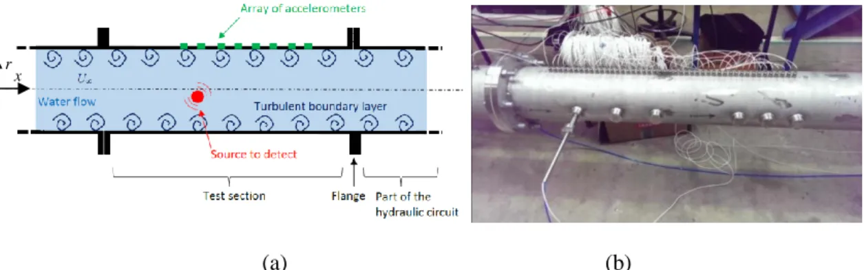
strong sodium/water chemical reaction caused by the leak generate acoustic noise. Acoustic techniques can be used to detect the leak quickly as the propagation time of the acoustic wave from the leak to the sensors on the external surface of the SGU is sufficiently short. However, these methods are very sensitive to the background noise caused by the sodium and water flows, boiling water and the vibrations induced by the pumps. Beamforming over an array of sensors is of particular interest due to its capacity to increase the signal-to-noise ratio of the acoustic signal induced by the water-sodium reaction, [1-4]. Moriot et al. [4] considered the conventional beamforming that it is based on the knowledge of the transfer functions between source to be detected and the array sensor. Moreover this treatment assumes that the background noise is spatially uncorrelated. In the numerical applications, the source was assumed to be an acoustic monopole (i.e. pulsating sphere). The steering vectors of the beamforming were therefore defined from the frequency transfer functions between an assumed position of the monopole source inside the detection space and the sensor mounted on the external surface of the shell. These steering vectors were given by a model taking into account of the strong interaction between the heavy fluid (i.e. sodium) and the cylindrical shell (i.e. external surface of the SGU). The numerical results obtained by Moriot et al. [4] showed that vibroacoustic beamforming using a linear array of accelerometers fixed on the external surface of the cylindrical shell can be used to localize the acoustic monopole and increase of the Signal to Noise Ratio (SNR). The works reported by Moriot in his thesis [5] were promising in terms of array gain but the numerical results were obtained by using simple academic models (an infinite plate or cylindrical) under the assumption of uncorrelated background noise. In this paper, we propose to improve the modelling to be more representative of the mock-up considered for the experiment and illustrated in Figure 1. This mock-up is composed of a cylindrical pipe filled with a heavy fluid (i.e. water rather than sodium for practical reasons) connected to the hydraulic circuit by two flanges. The source to be detected consists of a hydrophone used in transmission mode placed inside the pipe whereas the background noise may be controlled by changing the flow rate. The vibroacoustic beamforming consists in processing the signals of the accelerometers fixed on the pipe to enhance the source signal and reject the background noise.
(a) (b)
Figure 1. (a) schematic representation of the configuration considered for assessing the performance of the vibro-acoustic beamforming; (b), Picture of the test pipe with the
linear array of accelerometers.
x r
The model developed in this paper considers an infinite cylindrical shell filled with water and coupled to two ring stiffeners representing the flanges. A deterministic excitation as an acoustic monopole inside the fluid or a stochastic excitation as the turbulent boundary layer induced by the water flow are considered. The theoretical developments presented in section 2 are based on the circumferential admittance approach and a spectral decomposition of the vibratory/pressure fields. Numerical results for deterministic excitation (point force, monopole) and stochastic excitation (turbulent boundary layer) are shown in section 3 and compared with experimental results.
2. NUMERICAL MODELLING
2.1 Vibratory response of the shell excited by deterministic excitations
2.1.1 Circumferential admittance approach
One considers the system shown in Figure 1-a composed of an infinite cylindrical shell filled with a heavy fluid (water) and coupled to two ring stiffeners. In this section, one supposes that the system is excited either by a monopole inside the fluid or by a radial point force applied on the shell. The excitation is supposed harmonic with a time dependency in 𝑒𝑗𝜔𝑡 where 𝜔 represents the angular frequency. This time dependency
will be omitted of the notation in the following. The dynamic behavior of the thin cylindrical shell will be described by the Flûgge model whereas the acoustic behavior of the fluid will be represented by the Helmholtz model. Only the coupling along the radial direction between the shell and the stiffener will be considered for these first developments. The ring stiffener will be represented by a ring model (i.e. rod of circular curvature) [6]. A cylindrical coordinate system (𝑥, r, 𝜃) is considered. The two ring stiffeners are located at the axial positions, 𝑥1 and 𝑥2.
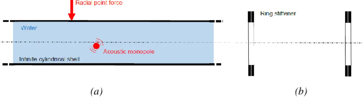
The global system is partitioned in two subsystems as shown in Figure 2. The fluid filled cylindrical shell constitutes one subsystem whereas the ring stiffeners constitutes the second subsystem.
(a) (b)
Figure 2. Partitioning of the vibroacoustic problem: (a), fluid filled cylindrical shell; (b), ring stiffeners.
One will use the circumferential admittance approach (CAA) [7] for assembling the two subsystems. One reminds here the principle of the approach (for more details, see [7]). • First, as the considered system is axisymmetric (excepted for the excitation), the different spatial fields (displacement, acoustic pressure, force) noted 𝑓 can be represented by a Fourier series decomposition about the circumference:
𝑓̃(𝑛) = 1 2𝜋∫ 𝑓(𝜃)𝑒−𝑗𝑛𝜃𝑑𝜃 2𝜋 0 , ∀𝑛 ∈ ℤ 𝑓(𝜃) = ∑ 𝑓̃(𝑛)𝑒𝑗𝑛𝜃 𝑛∈ℤ (1) (2) • Second, for each circumferential order n (omitted of the notation in the following), one defines the circumferential admittances 𝑌̃𝑖𝑗𝛼 (m2/N) of the shell (α=1) and of the ring stiffeners (α=2) between the junction i and j by:
𝑌̃𝑖𝑗𝛼 =𝑊̃𝑖,𝑗
𝛼
𝐹̃𝑖𝛼 , 𝑖 ∈ {1,2}, 𝑗 ∈ {1,2} (3)
where:
− 𝑊̃𝑖,𝑗𝛼 (m) is the circumferential radial displacement at the junction j (of the shell for 𝛼 = 1 or of the stiffeners for 𝛼 = 2 ) for a circumferential radial force applied at junction i; − 𝐹̃𝑖𝛼 (N/m) is the circumferential radial force applied at junction i on the shell by the
stiffeners for 𝛼 = 1 or the circumferential radial force applied on the stiffeners by the shell for 𝛼 = 2.
Moreover, for each subsystem α, one defines the circumferential free displacement at the junction i, 𝑊̅̃𝑖𝛼 as the circumferential radial displacement induced by the external excitation at the junction i when all the junctions are let free
• Finally, using the superposition principle for passive linear systems and considering the radial displacement continuity and the force equilibrium at the junctions, one finally obtains the matrix system [7]:
(𝑌̃1 + 𝑌̃2)𝐹̃𝑐 = 𝑊̅̃1 − 𝑊̅̃2 (4) where 𝑌̃𝛼 = [𝑌̃11𝛼 𝑌̃12𝛼 𝑌̃21𝛼 𝑌̃ 22𝛼 ] , 𝐹̃𝑐 = [𝐹̃11 𝐹̃21] , 𝑊̅̃𝛼= [ 𝑊̅̃1𝛼 𝑊̅̃2𝛼].
Resolving this equation system, one deduces the coupling forces exerted by the stiffeners on the shell. In a last step, one can introduce these forces in the model of the infinite fluid filled shell in order to estimate the vibratory field of the shell when it is coupled to the ring stiffeners. In the following, as no external excitation is contained in subsystem #2, one considers that 𝑊̅̃𝑖2 = 0 in Eq. (4).
2.1.2 Spectral approach for estimating the shell circumferential admittance and free displacement
The problem describing the vibroacoustic behaviour of the fluid loaded shell excited by a harmonic radial force is resolved using a spectral approach. The 2D Fourier transform (i.e. space Fourier transform about x-axis + Fourier serie decomposition about the circumference) is considered: 𝑓(𝑥, 𝜃) → 𝑓̃̃(𝑘𝑥, 𝑛, ) = 1 2𝜋 ∫ ∫ 𝑓(𝑥, 𝜃)𝑒−𝑗𝑘𝑥𝑥 2𝜋 0 𝑒−𝑗𝑛𝜃 +∞ −∞ 𝑑𝜃𝑑𝑥 (5)
where 𝑓 is a generic function representing either the shell displacements or the acoustic pressure.
Applying this transform to the Flügge, Helmholtz, and Euler equations describing the behaviour of the fluid filled shell, one obtains finally [7]
𝑊̃̃ = 𝛾𝐹̃̃𝑤𝑍̃̃𝑢𝑢𝑍̃̃𝑣𝑣− (𝑍̃̃𝑢𝑣)
2
Δ̃̃
(6)
where 𝑍̃̃𝜁𝜉 are the components of the spectral Flügge matrix, Δ̃̃ is the determinant of the
spectral Flügge matrix taking into account of the spectral fluid loading impedance and 𝛾 is a constant depending on the shell characteristics.
In order to estimate the circumferential admittances of the fluid filled cylindrical shell, one considers the shell excited by a radial circumferential force at x=0 of unit magnitude for each circumferential order, n. As the considered system is invariant in translation about the axial direction, the admittance between junctions i and j can be deduced from
𝑌̃𝑖𝑗1 =𝑊̃ (𝑥𝑖− 𝑥𝑗, 𝑛)
𝐹̃ (7)
where 𝑊̃ is the radial displacement of the shell excited by a unitary radial circumferential force 𝐹̃ at x=0 (𝐹̃=1 N/m).
The spectral radial force for the unitary circumferential radial force applied at x=0 is 𝐹̃̃𝑤 = 1 N/m. The spectral radial displacement 𝑊̃̃ can then be calculated analytically using Eq. (6). The circumferential displacement 𝑊̃ can be obtained from an inverse Fourier transform about x:
𝑊̃ (𝑥, 𝑛) = 1
2𝜋∫ 𝑊̃̃ (𝑘𝑥, 𝑛)𝑒𝑗𝑘𝑥𝑥𝑑𝑘𝑥
∞
−∞ (8)
This operation is achieved numerically after reducing the infinite wavenumber space to the interval [ −𝑘̅𝑥, 𝑘̅𝑥] where 𝑘̅𝑥 a cut-off wavenumber judiciously chosen to avoid the
loss of significant contributions. The shell admittances are then deduced from Eq. (7).
The same approach is used for estimating the free circumferential radial displacement 𝑊̅̃1. The spectral radial force is then
𝐹̃̃𝑤 =𝑒−𝑗(𝑛𝜃𝑠+𝑘𝑥𝑥𝑠
)
2𝜋
(9)
for a unit radial point force applied on the shell at (𝑥𝑠, 𝑅, 𝜃𝑠), and,
𝐹̃̃𝑤=𝑒−𝑗(𝑛𝜃𝑠+𝑘𝑥𝑥𝑠 ) 𝜋𝑘𝑟𝑅 𝐽𝑛(𝑘𝑟𝑟𝑠) 𝐽′ 𝑛(𝑘𝑟𝑅) (10) for a unit mass rate monopole located in the fluid at (𝑥𝑠, 𝑟𝑠, 𝜃𝑠), where 𝐽𝑛 is the Bessel
function of order n, R, the shell radius and 𝑘𝑟 is the appropriate solution of 𝑘𝑥2 + 𝑘𝑟2 = 𝑘𝑜2 with 𝑘𝑜, the acoustic wavenumber.
By injecting Eq. (9) or Eq. (10) in the Eq. (6), one obtains the Fourier transform of the free displacement. The free displacement at the position of the stiffeners are obtained numerically using Eq. (8).
2.1.3 Model of the ring stiffener
As the two stiffeners are not physically coupled, one has 𝑌̃122 = 𝑌̃212 = 0 and as they are
identical, 𝑌̃112 = 𝑌̃
222 = 𝑌̃𝑟.
Each ring is represented by a rod of circular curvature and of rectangular cross-section. 𝑙𝑟, ℎ𝑟 , 𝜌𝑟, 𝑐𝑟 represent the width, height of the cross section, density of the material and
celerity of the extensional waves. Neglecting inertia and rotary effect, one can determinate its circumferential admittance, 𝑌̃𝑟 (m/N) [6]:
𝑌̃𝑟 = 1 [ 𝜌𝑟𝑐𝑟2𝐴 𝑟 𝑅2 [1 − 𝛺𝑟2+ 𝛽𝑟2𝑛4+ ( 𝑛2(1 + 𝛽 𝑟2𝑛2)2 𝛺𝑟2− 𝑛2(1 + 𝛽 𝑟2))] ⁄ (11) where 𝛽𝑟2 = ℎ𝑟2 12𝑅2, 𝑘𝑟 = 𝜔 𝑐𝑟, 𝛺𝑟= 𝑅 𝑘𝑟, 𝐴𝑟 = 𝑙𝑟ℎ𝑟.
2.1.4 Displacements of the shell coupled to the ring stiffener
Once upon the shell and stiffener admittances have been estimated as well as the free displacements induced by the external excitation, one can deduce the coupling forces with Eq. (4). These forces should be reinjected in the spectral model of the fluid filled shell described in section 2.1.2. The spectral radial forces write in this case:
𝐹̃̃𝑤 = 𝐹̃̃𝑒+ 𝐹̃11𝑒−𝑗𝑘𝑥𝑥1 + 𝐹̃
21𝑒−𝑗𝑘𝑥𝑥2 (12)
where 𝐹̃̃𝑒 are the spectral radial forces due to the external excitation (see Eq. (9-10)). The spectral radial displacement of the fluid filled shell coupled to the ring stiffeners is then obtained by injection Eq. (12) in Eq. (6). The radial displacement in the physical space is then deduced from the inverse Fourier transform (approximated numerically in practice): 𝑤(𝑥, 𝜃) = 1 2𝜋 ∑ 𝑒𝑗𝑛𝜃 ∞ 𝑛=−∞ ∫ 𝑤∞̃̃(𝑘𝑥, 𝑛) −∞ 𝑒𝑗𝑘𝑥𝑥𝑑𝑘 𝑥 (13)
2.2 Vibratory response of the shell excited by the turbulent flow
Now let us considered the fluid filled shell excited by a turbulent flow. The flow speed is supposed to be low compared to the acoustic speed and the turbulent boundary layer (TBL) excited the wall of the shell is supposed homogeneous, stationary and fully developed. The effect of the convection on the acoustic behaviour is neglected. The Cross Spectrum Density (CSD) of the Wall Pressure Field (WPF) induced by the TBL, 𝜙𝑝𝑝 will
be estimated from the TBL parameters and a mixed Goody-Chase 1987 model [8,9]. Considering the Fourier transform defined by Eq. (5) for our cylindrical system, the CSD of the WPF expressed in the (𝑘𝑥, 𝑛) domain 𝜙𝑝𝑝𝑅 can be related to the CSD of the WPF
given in the literature for flat walls, 𝜙𝑝𝑝 by:
𝜙𝑝𝑝𝑅 (𝑘𝑥, 𝑛, 𝜔) =
1
2𝜋𝑅𝜙𝑝𝑝(𝑘𝑥, 𝑛
𝑅, 𝜔) (14)
The CSD of the radial shell displacement between the points of coordinates (𝑥, 𝜃) and ( 𝑥′, 𝜃′), 𝑆
𝑤𝑤𝑅 can be written (see [10-14]):
𝑆𝑤𝑤𝑅 (𝑥, 𝜃, 𝑥′, 𝜃′, 𝜔) = 2𝜋 ∑ ∫ 𝐻̃̃𝑤𝜔 ∗ (𝑥, 𝜃, 𝑘𝑥, 𝑛) +∞ −∞ +∞ 𝑛=−∞ 𝜙𝑝𝑝𝑅 (𝑘𝑥, 𝑛, 𝜔) 𝐻̃̃𝑤𝜔 (𝑥′, 𝜃′, 𝑘𝑥, 𝑛)𝑑𝑘𝑥. (15)
where the sensitivity functions, 𝐻̃̃𝑤𝜔 are expressed (using the reciprocity principle as
described in [10]),
𝐻̃̃𝑤𝜔(𝑥, 𝜃, 𝑘𝑥, 𝑛) =2𝜋 1 ∫−∞+∞∫ 𝐻02𝜋 𝑤(𝑥̃, 𝜃̃, 𝑥 , 𝜃, 𝜔)e−𝑗𝑘𝑥x̃𝑒−𝑗𝑛𝜃̃𝑑x̃𝑑𝜃̃. (16)
In Eq. (16), 𝐻𝑤(𝑥̃, 𝜃̃, 𝑥 , 𝜃, 𝜔) corresponds to the radial displacement of the shell at point M̃ of coordinates (𝑥̃, 𝜃̃) when the shell is excited by a unitary radial point force at point M of coordinates (𝑥 , 𝜃). Considering the definition of the Fourier transform given by Eq. (6), its results that the sensitivity functions 𝐻̃̃𝑤𝜔 given by Eq. (16) correspond to the Fourier
transform of the shell radial displacement field (expressed in ( 𝑘𝑥, 𝑛) space) when the
shell is excited by a unitary radial point force at point M. For the fluid filled shell coupled to the two ring stiffeners, these quantities can be calculated using the CAA approach described in section 2. For calculating the sensitivity functions at a given point M, it is necessary to consider a unitary radial point force at this point, to calculate the coupling forces by resolving Eq. (4), and to evaluate the spectral radial displacement of the shell directly from Eq. (6) with Eq. (12).
The CSD of the radial displacement excited by the TBL can then be estimated using Eq. (15), the sensitivity functions 𝐻̃̃𝑤𝜔 estimated with the CAA approach and the CSD of the
3. RESULTS FOR DIFFERENT LOAD CASES
In this section, some numerical results are presented for the mock-up (see Figure 1) considered for the laboratory experiment. The cylindrical pipe is made of stainless steel. The length between the two flanges, the diameter and the thickness are respectively, 3.1 m, 219 mm and 8 mm. The cross-section of the steel flanges (i.e. ring stiffeners) is 60 × 40 mm2. The pipe is filled with water. Damping loss factors have been set to 1% for steel and 0.1% for water.
3.1 Radial point force excitation
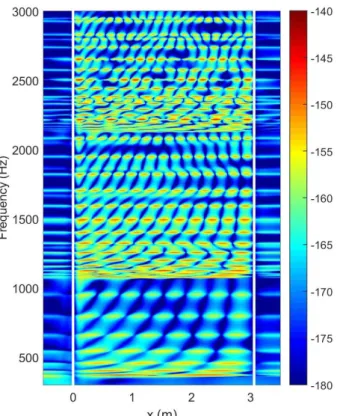
Figure 3 shows the level of the radial displacement of the shell excited by a unitary point force at point of coordinates (xs, θs)=(0.14 m,0°). The results are given along the
generating of the cylinder θ=0°. The position of each stiffener is represented by vertical white line.
Figure 3. Displacement level (ref. dB, 1 m) in function of the axial position (θ=0°) and the frequency. Radial point force excitation at xs=0.14 m and θs=0°. Ring stiffener
positions symbolized by vertical white line.
The cut-on frequency of the first circumferential orders are: 363 Hz for n=2, 1079 Hz for
n=3, 2145 Hz for n=4 and 3549 Hz for n=5. One can clearly observe the effect of the
apparition of the propagative waves associated to these circumferential orders. As it could be expected, one can also notice a significant decrease of the vibratory field passing the ring stiffeners. Moreover, the stiffeners induces some reflexions of the vibroacoustic waves that lead to the apparition of pseudo-axial modes after each cut-on frequency.
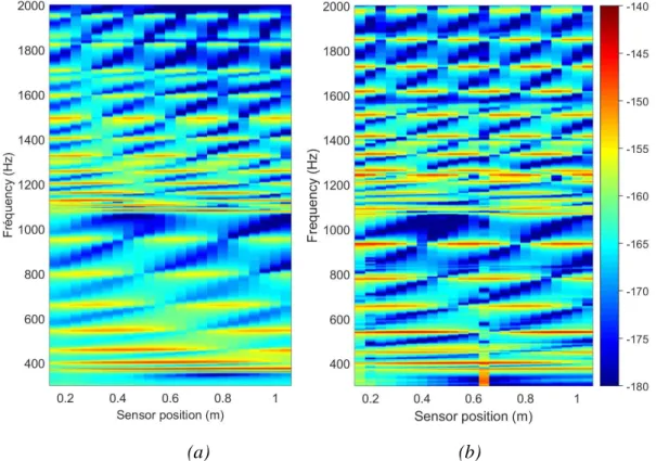
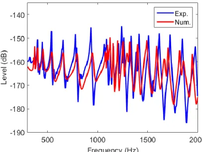
Results are compared in Figure 4 with measurements by a line array of 24 accelerometers fixed on the cylindrical generator θ=0° with a spacing of 4 cm. Globally, a good agreement can be observed. The patterns related to the cut-on frequencies and the pseudo axial modes are similar. Below 1 kHz, one can however notice that the magnitudes of the pseudo axial modes are significantly lower than those measured, as highlighted in Figure 5. This can be due from one hand, to an inappropriate value of the steel damping loss factor for these frequencies and from another hand, to an inappropriate model for representing the flanges. Indeed, in this first model, by simplicity, one has neglected the torsional, axial, and tangential stiffness of the flanges. A coupling about these supplementary degrees of freedom between the shell and the stiffness could be introduced in the future using the same methodology that presented in this paper.
(a) (b)
Figure 4. Displacement level (ref. dB, 1 m) at the sensor position: (a), numerical results; (b), experimental results. Radial point force excitation at
Figure 5. Numerical-experimental comparison of the displacement level (ref. dB, 1 m) at the applied force position (i.e. xs=0.14 m, θs=0°).
3.2 Monopole source
Figure 6 shows the same type of comparison than Figure 4, but for two positions of the acoustic source into the fluid. Experimentally, the source was a small hydrophone used in emitter mode. Only experiment results above 1 kHz are exploitable. At the first sight, the numerical-experiment comparison could appear less encouraging than for the mechanical excitation. However, one can notice some similarities between the numerical and experimental results: (a), globally, the levels are significantly higher for the radial position rs=0.088 m than for rs=0.05 m (that can be explained by a source closer to the
shell wall for rs=0.088 m); (b), the effect induced by the apparition of propagative waves
at the cut-on frequencies can be identified; (c), above 2.5 kHz, the fluid filtering effect appears significant for rs=0.05 m. One can emphasize that the size and the mounting
support of the experiment source can be at the origin of discrepancies. In particular, vibration transmission between the hydrophone and the shell wall through the mounting support could be incriminated.
(a) (b)
(c) (d)
Figure 6. Numerical-experimental comparison of the displacement level (ref. dB, 1 m) for two radial monopole positions: (a-b), rs=0.088 m ; (c-d), rs=0.05 m. Type of results:
(a, c), numerical; (b, d), experimental. Axial monopole position, xs=0.56 m, angular
monopole position, θs=90°.
3.3 Turbulent boundary layer excitation
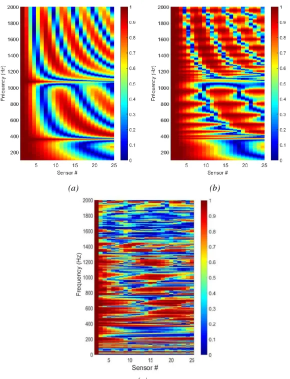
As the performances of the classical beamforming treatment depend on the coherence of the background noise, we study here the spatial coherence of the shell vibration induced by the turbulent flow. Figure 7 shows the coherence between sensor #2 and the others sensors when the shell is excited by the turbulent boundary layer for a flow rate of 140 l/s (i.e. free stream velocity 𝑈∝ = 4.5 m/s).
(a) (b)
(c)
Figure 7. Normalized cross spectrum density function of the shell displacement
between sensor #2 and the sensor #i∈ ⟦2,25⟧. (a), numerical results for the shell
without the stiffeners; (b), numerical results for the shell with the stiffeners; (c), experimental results for the shell with the stiffeners. Flow rate: 140 l/s.
Eq. (15) has been used for the numerical calculations using the hybrid Corcos-Chase 1987 model. The thickness of the TBL is supposed to be equal to the shell radius whereas the friction velocity, 𝑈𝜏 is estimated with the relation 𝑈𝜏 = 0.32𝑈∝ [15].
For the experimental investigation, a particular attention has been paid to decouple the test section from external mechanical sources (by fixing the pipe with rubber seals on a
suspended slab) and from external fluid sources (by using acoustic decoupling balloons). Upstream the test section, a 4 m long pipe and a perforated plate flow conditioner are used to stabilize the turbulent flow whereas a 1.5m long pipe is used for the discharge before the acoustic balloon.
One can observe from the different results of Figure 7 that the shell vibrations calculated or measured at the sensor positions appear highly coherent at some frequencies. This result was not expected at the first sight as the WPF induced by the TBL is known to be highly incoherent at distances corresponding to the sensor spacing. For instance, the coherent length estimated in the stream wise direction with the Corcos model [16] is 1.3 × 10⁻³ m at 1 kHz whereas the sensor spacing is 4 × 10⁻² m. As it is of almost one order
of magnitude lower than the sensor spacing, one could expect a weak coherence of the sensor signals. Manifestly, it appears that it is not the case. Even if the considered system is excited by a uniformly distributed and weakly correlated excitation, it appears that the reaction of the system leads to a vibratory response strongly correlated in space for some frequencies. From the numerical results of Figure 7-a (unstiffened shell) and Figure 7-b (stiffened shell), one can relate these particular frequencies to the cut-on frequencies of the circumferential orders and the resonance frequencies of the pseudo axial modes. Finally, one can observe that these strong coherences of the vibratory field can also be observed experimentally as shown on Figure 7-c.
4. CONCLUSIONS
The vibroacoustic response of the fluid filled cylindrical shell coupled to two ring stiffeners and excited by deterministic (force/monopole) or stochastic (TBL) sources has been predicted using the circumferential admittance and spectral approaches. The calculation process has been presented considering only the radial coupling between the shell and the stiffeners. It can be extended to take into account the coupling in others directions (axial, tangential, rotation). This will be done in the next future, in particular to study the influence on the shell vibration of thetwist stiffness of the ring stiffeners. This numerical process can be used to achieve “virtual experiments” in order to study the efficiency of vibratory monitoring techniques for detecting an acoustic source inside the pipe ([14]).
5. ACKNOWLEDGEMENTS
This work was carried out in the framework of the LabEx CeLyA ("Centre Lyonnais
d'Acoustique", ANR-10-LABX-60) and the Sodium Technology project of GEN4 program (R4G/TECNA) of the Nuclear Energy Division of CEA (CEA/DEN).
6. REFERENCES
[1] Kim, T., Yugay, V. S., Jeong, J., Kim, J., Kim, B., Lee, T., Lee, Y., Kim, Y., Hahn D. Acoustic Leak Detection Technology for Water/Steam Small Leaks and Microleaks Into Sodium to Protect an SFR Steam Generator. Nucl. Technol. 170 (2010) 360-369.
[2] Chikazawa, Y., Acoustic leak detection system for sodium-cooled reactorsteam generators using delay-and-sum beamformer. J. Nucl. Sci. Technol. 47 (2010), 103–110. [3] Chikazawa, Y., Yoshiuji, T., Water experiment on phased array acoustic leak detection
system for sodium-heated steam generator. Nucl. Eng. Des. 289 (2010) 1-7.
[4] Moriot, J., Maxit, L., Guyader, J.L., Gastaldi, O., Périsse, J., Use of beamforming for detecting an acoustic source inside a cylindrical shell filled with a heavy fluid. Mech. Syst. Signal Process 52–53 (2015) 645–662.
[5] Moriot, J., 2013. Passive vibroacoustic detection of a water-sodium reaction using beamforming on a steam generator of a liquid sodium fast reactor, PhD thesis, INSA Lyon, France, 158 p. (in French).
[6] Tran-Van-Nhieu, M., Scattering from a ribbed finite cylindrical shell. The Journal of the Acoustical Society of America, 10 (2001), 2858–2866
[7] Maxit L., Ginoux J.M., Prediction of the vibro-acoustic behavior of a submerged shell non periodically stiffened by internal frames, JASA, 128 (2010) 137-151.
[8] Goody, M.C., Empirical spectral model of surface pressure fluctuations, AIAA J., 42 (2004) 1788–1794.
[9] Chase, D.M., The character of the turbulent wall pressure spectrum at subconvective wavenumbers and a suggested comprehensive model, J. Sound Vib. 112 (1987) 125-147. [10] Maxit, L., Denis, V., Prediction of flow induced sound and vibration of periodically
stiffened plate, JASA, 133 (2013) 146-160.
[11] Meyer, V., Maxit, L., Renou, Y., Audoly, C., Vibroacoustic modelling of submerged stiffened cylindrical shells with internal structures under random excitations.
Proceedings of INTERNOISE 2016, Hamburg, Germany, August 2016. 12 p.
[12] Maxit, L., Meyer, V., Vibroacoustic modelling of periodically stiffened submerged cylindrical shells beneath a turbulent boundary layer, Proceedings of INTERNOISE
2017, Honk Kong, August 2017. 11 p.
[13] Meyer, V., Development of a substructuring approach to model the vibroacoustic behavior of submerged stiffened cylindrical shells coupled to non-axisymmetric internal frames, PhD thesis, INSA Lyon, 2016.
[14] Kassab, S., Vibroacoustic beamforming for the detection of an acoustic monopole inside a thin cylindrical shell coupled to a heavy fluid: Numerical and experimental developments, PhD thesis, Université de Lyon, INSA Lyon, Villeurbanne, France, 2018, 182 p. (in French).
[15] Bonness, W., Capone, D., Hambric, S., Low-wavenumber turbulent boundary layer wall-pressure measurements from vibration data on a cylinder in pipe flow, J. Sound Vib.329 (2010) 4166-4180.