HAL Id: hal-00799836
https://hal.archives-ouvertes.fr/hal-00799836
Submitted on 2 Sep 2020HAL is a multi-disciplinary open access archive for the deposit and dissemination of sci-entific research documents, whether they are pub-lished or not. The documents may come from teaching and research institutions in France or abroad, or from public or private research centers.
L’archive ouverte pluridisciplinaire HAL, est destinée au dépôt et à la diffusion de documents scientifiques de niveau recherche, publiés ou non, émanant des établissements d’enseignement et de recherche français ou étrangers, des laboratoires publics ou privés.
New ”one-step” method for the simultaneous synthesis
and anchoring of organic monolith inside COC
microchip channels
Yoann Ladner, Anthony Bruchet, Gérard Crétier, Vincent Dugas, Jérôme
Randon, Karine Faure
To cite this version:
Yoann Ladner, Anthony Bruchet, Gérard Crétier, Vincent Dugas, Jérôme Randon, et al.. New ”one-step” method for the simultaneous synthesis and anchoring of organic monolith inside COC microchip channels. Lab on a Chip, Royal Society of Chemistry, 2012, 12 (9), pp.1680-1685. �10.1039/c2lc21211k�. �hal-00799836�
New « one-step » method for the simultaneous
synthesis and anchoring of organic monolith
inside COC microchip channel
Y. Ladner1, A.Bruchet1,2, G. Crétier1, V.Dugas1, J.Randon1 and K. Faure1
1.
Institut des Sciences Analytiques, UMR UCBL - CNRS 5280, Université de Lyon
Université Claude Bernard Lyon 1
43 boulevard du 11 Novembre 1918, bâtiment Curien 69622 Villeurbanne, France
karine.faure@univ-lyon1.fr
2.
Laboratoire d'Analyses Nucléaires Isotopiques et Elémentaires Commissariat à l'Energie Atomique (CEA - Saclay)
91191 Gif-sur-Yvette CEDEX
1. Abstract
A new method of monolith synthesis and anchoring inside cyclic olefin copolymer (COC) microchannels in a single step is proposed.
This work demonstrates that type I photoinitiators that are typically used in polymerization mixture to generate free radicals during monolith synthesis can simultaneously act as type II photoinitiators and react with plastic surface through hydrogen abstraction.
To exemplify this mechanism, COC surfaces were photografted with poly(ethylene glycol) methacrylate (PEGMA). Contact angle measurements were used to observe the changes in surface hydrophilicity when increasing initiator concentration and irradiation duration.
The ability of type I photoinitiator to synthetize and anchor a monolith inside COC microchannels in a single step was proved through SEM analysis, using different concentrations of photoinitiators. Finally, electrochromatographic separations of hydrocarbon aromatic polycyclic were realized to illustrate the beneficial effect of anchoring on chromatographic performances The versatility of the method was demonstrated with two widely-used monoliths: an hydrophobic hexyl acrylate monolith and a more hydrophilic glycidyl methacrylate monolith with benzoin methyl ether (BME) and 2-azobis isobutyronitrile (AIBN) photo-initiators respectively.
Keywords : Cyclic olefin copolymer / Photografting / surface modification / type I photoinitiators / Benzoin methyl ether / azobisisobutyronitrile (AIBN) / monolith / benzophenone
2. Introduction
Monoliths have been extensively studied as stationary phase in miniaturized format such as capillaries and microchips [5, 6]. Their synthesis, based on the polymerization of monomers in the presence of porogen, can easily be conducted in situ and the resulting continuous bed exhibits a bimodal structure with large through-pores for flow and small pores for retention . To the best of our knowledge, in-situ synthesis of monoliths is the simplest way to introduce a stationary phase in microchip [2-4][7, 8]. The first syntheses of organic monoliths for chip-EC purposes were carried out in glass chips, whose material is similar to fused-silica capillaries [2, 9].
Compared with this traditional substrate, the advantages of polymer-based microfluidic devices include the reduced costs, relative ease of fabrication and availability of a wide range of plastics with different properties . The most widely spread polymeric material for cheap microfluidic
application is polydimethylsiloxane (PDMS). However, the implementation of monoliths in this material is particularly difficult, since absorption of monomers and porogen into PDMS is recurrent [11]. Cyclic olefin copolymer (COC) is of particular interest due to its combination of excellent UV transparency, low auto fluorescence, high mechanical strength and compatibility with a broad range of chemicals and solvents [13-15]. Previous papers have already demonstrated that acrylate and methacrylate-based monoliths could be synthetized in situ without anchoring to the walls in COC microchannels in chip-EC [16, 17].
However, non-anchored monoliths involve low efficiencies with plates heights reaching down to 15 μm when working at optimal velocity in chip-EC [16]. Moreover, non-anchored monolith can not be used in pressure-driven chromatography due the monolith movement under pressure. Therefore it is necessary to anchor the monolith onto COC walls.
In literature, several researcher groups have worked on the COC functionalization, mainly in order to minimize adsorption of analytes such as proteins. Today, there are two main ways of COC surface treatments: physical and chemical functionalization.
Physical treatments have been extensively used. A plasma oxidation followed by application of silane reagents (tetraethyl orthosilicate or TEOS) allows to incorporate Si functionalities on the polymer, facilitating siloxane bonds between the two polymers [19]. Unfortunately, these methods can not be used directly in microchannels.
The second method, chemical treatment, is well suited for microchannels. Mecomber’s group [20] proposes the topochemical modification of polymer surfaces with perfluorinated aromatic azides. The aryl azides, which have quaternary amine or aldehyde functional groups, were linked to the surface of the polymer by UV irradiation. Koponen et al [21] have developed a method where COC surfaces were patterned with nanopillars or with microbumps on which nanopillars were superimposed. Patterning was achieved by applying nanoporous anodized aluminum oxide (AAO) membrane as a mask in injection molding or imprinting. This method results in a superhydrophobic surface.
Conventional surface photo-initiated free radical polymerization can be directly used both on substrate surface and inside microfluidic channels. In this process, “Type II” photoinitiators such as benzophenone have been frequently used to abstract hydrogen atoms from the surface polymer chains, thus forming surface radicals [22] . This mechanism was first introduced by Ranby’s group [23] . Using this method, Stachowiak et al [10] and Deverral et al. [24] reported the surface modification of COC microchannels either to increase surface hydrophilicity with hydrophylic monomer PEGMA in order to reduce protein adsorption or to prepare polymer monolith with good flow-through properties for heterogeneous palladium catalysis.
The functionalization of COC surfaces can be obtained in either one-step [25] or two-step [10] method by grafting PEGMA on COC surfaces with benzophenone. As water droplet contact angles decreased from 88° for native COC to 45° for PEGMA-grafted surfaces, protein adsorption was also reduced by 78% for the PEGMA-modified COC micro-channels as determined by fluorescence assay.
Benzophenone is also used as intermediary to anchor organic monolith inside COC microchannels. Several researcher groups have reported a two-step functionalization followed by the in-situ synthesis of the monolith via-UV initiated polymerization [14,22,25]. In the first step, surface-bound initiators are formed when UV-excited benzophenone molecules abstract hydrogen atoms from the polymer surface. Surface radicals are created, but in the absence of monomer, these radicals combine with the newly formed semipinacol radicals to form covalently attached surface initiators. In the second step, graft polymerization from the polymer surface is initiated by UV irradiation of these sites in the presence of a solution containing monomer but no initiator. Although numerous grafting approaches have been demonstrated, most contain drawbacks. The COC functionalization in one step with benzophenone can clogged the microchannels. Moreover, for the three-step mechanism to anchor and to synthetize monolith inside COC microchannels, lacks of reproducibility of the overall procedure could be observed. The other drawback of the use of benzophenone to abstract hydrogen atoms is that the wavelength has to be fixed at 254 nm to be in optimal conditions [27] . However, most of Topas COC materials have a high absorption level at this wavelength [28]. This high absorption can induce lacks of homogeneity in the functionalization of COC microchannels. The main drawback is that the photoinitiator used to functionalize COC surfaces is different from the one used for monolith synthesis.
We propose here a new method for the synthesis and anchoring of organic monolith inside COC microchip channel to avoid these precited problems. Type I photoinitiators such as AIBN or BME, extensively used in monolith synthesis [29-31]. Less known, they can also act as type II
photoinitiators and abstract hydrogen atoms from a plastic surface [34]. Our proposal is to use this hydrogen abstraction mechanism on COC surfaces with type I photo-initiator to functionalize the polymeric material. UV-excited type I photoinitiator will simultaneously a cleavage to yield free radicals and abstract hydrogen atoms from the polymer surface. This mechanism would allow to anchor and to synthetize a monolith in COC microchannels in a single step. The main advantage of this one-pot synthesis is to use the same photoinitiator to synthetize and to anchor a monolith inside COC microchannels, avoiding lack of homogeneity and speeding up the overall production process.
We now report the surface modification of COC surfaces by using type I photoinitiators and poly(ethylene glycol) monomethacrylate (PEGMA) in order to increase their surface hydrophilicity. This change of hydrophilicity was characterized by contact angle measurements showing that type I photoinitiators are able to abstract hydrogen atoms on COC surfaces. Then, SEM studies are realized to show the ability of BME and AIBN to anchor the monolith to the inner wall of COC microchannels. The influence of the quantity of initiators on the monolith anchoring onto COC microchannels was observed. Finally, electrochromatographic separations of hydrocarbon aromatic polycyclic (HAP) were realized to illustrate the interest of the new-one step method for the simultaneous synthesis and anchoring of organic monolith inside COC microchip channel. The versatility of the method was demonstrated with two widely-used monoliths: hydrophobic hexyl acrylate monolith and more hydrophilic glycidyl methacrylate monolith.
3. Experimental
3.1. MaterialsHexyl acrylate (HA), 1,3-butanediol diacrylate (BDDA), Glycidyl methacrylate (GMA), Polethylene glycol dimethacrylate (EDMA), 2-acrylamido-2-methyl-1-propanesulfonic acid (AMPS), Polyethylene glycol methacrylate (PEGMA), 1,4-butanediol, 1-propanol, azobisisobutyronitrile (AIBN) and benzoin methyl ether (BME) were obtained from Acros Organics (Noisy-Le-Grand, France). Ammonium phosphate (NH4H2PO4) was from Sigma-Aldrich (Isle-d’Abeau, France). Acetonitrile and ethanol were HPLC-grade from SDS (Peypin, France). The microfluidic devices made of cyclic olefin copolymer (COC) were fabricated by Microfluidic Chipshop GmbH (Jena, Germany). Microfluidic chips used have a single channel with two molded reservoirs. The length of separation channel is 58.5 mm and the channels are 100 µm deep by 100 µm wide. 3.2. Instrumentation
The illumination system used to perform UV irradiation was a Bio-link cross-linker (VWR International, Strasbourg, France) equipped with five 8W UV tubes, emitting at 365 nm.
The contact angle of PEGMA-coated COC surface was determined using GBX Instruments Digidrop Contact angle Meter at room temperature. A droplet of 3 μL was placed slowly on the surface and after 30 s, contact angle was measured. The reported contact angles are averages of at least three measurements at different locations.
A JEOL JSM 6700F scanning electron microscope (SEM) (Tokyo, Japan) was used for both observations monolith grafting onto COC materials and estimations of the nodule size.
Microchip analyses were monitored by inverted fluorescence microscopic system (IX-71, Olympus, France) equipped with a 100 W mercury lamp and 330 nm excitation filter (collection above 400 nm) (XF02-2, Omega, USA) for the detection of fluorescent PAH. A CCD camera was combined with NI Vision software (Alliance Vision, France) for detection processing. High-power supply (Micralyne, Canada) was used to apply electric fields to the microchannels through platinum electrodes placed in the reservoirs. All system operations were performed with Labview 7.1 (National Instrument, Austin, TX, USA).
3.3. COC surface charaterisation
COC planar surfaces were modified using a sequential one-step photografting procedure to show the ability of the Type I photoinitiator to abstract hydrogen atoms on COC surfaces. A graft polymerisation solution was made by mixing 30 μL of PEGMA (0.1 M), 70 μL of acetone, and type I photo-initiator (BME or AIBN). The quantity of initiator varies from 0.5 to 5 wt%. The solutions of PEGMA were sealed in the space between two COC plates and then exposed to UV irradiation at 365 nm. The COC planar surfaces was then rinsed extensively with water and ethanol to remove the unreacted PEGMA and sonicated to eliminate homopolymers. The remaining anchored PEGMA, inducing a change in hydrophilicity, are characteristic of hydrogen abstraction mechanism. The COC functionalization was characterized by contact angle measurement.
3.4. Preparation of monolithic columns in microchip COC
Two types of polymerization mixture were prepared as follows. The first one, hydrophobic monolith (A), is used to separate neutral compounds by electrochromatography in capillary [35]. The porogenic mixture was made up of 54 % of ACN, 23 % of ethanol, and 23 % of water. Porogenic mixture was dissolved in monomer mixture containing 66.4 % of HA and 33.6 % of BDDA. The ratio of monomer to porogenic mixtures was 34.5:65.5. AMPS (0.5 % of monomers) is added in the polymerization mixture in order to support the electroosmotic flow. BME was used as radical photoinitiator at different percentage (0.5, 1.5, 2.5 and 3 % of monomers), 0.5 % being the amount usually used in capillary. BME is not soluble when the percentage is greater than 3%. The second one B, more hydrophilic, is widely used in particular for ion-exchange chromatography [Bruchet et al, J Sep Sci, in press]. The porogenic mixture was made up of 52.7 % of 1-propanol, 38 % of 1,4-butanediol and 9.3 % of water. Monomer mixture constituted of 75.4 % of GMA and 24.6% of EDMA was then dissolved in the porogen. The ratio of monomer to porogenic mixtures was 49.9:50.1. AIBN was used as radical photoinitiator at different percentage (1, 3, 4 , 5 and 7.5 % of monomers), 1 % being the amount usually used in capillary.
AIBN is not soluble when the percentage is greater than 7.5%. All percentages are expressed in weight.
The polymerization mixtures were introduced in the microchannels by pressure using a syringe. The microchip was submitted to a subsequent irradiation at 365 nm during 20 min (E = 1.9 J/cm²) for monolith A and 30 min (E = 2.85 J/cm²) for monolith B. Channels were then rinsed with ACN/water 70/30 (v/v) + 2 mM NH4H2PO4 + 5 mM LiDS for 30 min by applying an electric field of 617 V/cm to remove any remaining reactant.
3.5. Electrochromatography procedure in microchannel
Solute injection in the separation channel was realized by using the simple direct injection mode introduced in a previous publication, where a single electric field is applied across the separation channel [16]. The main advantage of this method is to avoid voltage programs. Briefly, this injection is composed of four steps: sampling step, injection, rinsing and separation step. In the sampling step, a droplet of 2 µL of sample mixture is placed in the hole of the inlet reservoir. An electric field is then applied during several seconds to introduce the sample mixture in the channel (injection step). The inlet reservoir is then fully washed with mobile phase, which avoids sample leakage. Finally, an electric field is applied during separation step. The fluorescence detection length is 3.5 cm.
4. Results and discussion
A photoinitiator is a compound especially added to a formulation to convert absorbed light energy, UV or visible light, into chemical energy in the form of initiating species, free radicals or cations. Based on the mechanism by which initiating radicals are formed, photoinitiators are generally divided into two classes: • Type I photoinitiators undergo a unimolecular bond cleavage upon irradiation to yield free radicals.
• Type II photoinitiators undergo a bimolecular reaction where the excited state of the photoinitiator interacts with a second molecule (a coinitiator) to generate free radicals.
(definition sigma à réécrire)
Type I photoinitiators undergo a homolytic bond cleavage upon absorption of light to produce free radicals. Irradiation of benzoin ethers in benzene solution results in the formation of benzaldehyde, benzyl and an equimolar mixture of diastereomeric pinacol ethers [34] .
Benzaldehyde is produced by hydrogen abstraction intra-molecular from radicals [34] or from the solvent [36] . BME may hence exhibit a minor mechanism of hydrogen abstraction like type II photo-initiator. This minor mechanism has to be proven by contact angle measurements, SEM studies and electrochromatographic separations.
4.1. Formation of surface initiators by hydrogen abstraction
In this study, we focused on photografting COC surfaces with PEGMA and evaluated the effect of grafting conditions. PEGMA is a hydrophilic monomer extensively used to improve the hydrophilicity of COC surfaces [10, 25]. In this study, we induce a photopolymerization of PEGMA
from BME initiation in a close contact with COC. The main proportion of PEGMA monomers react with free BME radicals. But once these homopolymers are removed, the remaining anchored PEGMA, are characteristic from hydrogen abstraction mechanism on COC surface. Due to its hydrophilic character, PEGMA is here used as a marker to monitor hydrogen abstraction on COC surface.. The effects of the irradiation time and the concentration of both initiators used were investigated. The static contact angle of water on the PEGMA-modified COC surfaces was measured to quantify the effectiveness of the surface modification procedure.
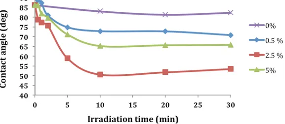
Figure 1 shows that no contact angle variations were noted when no initiator is present in the graft polymerization. No PEGMA adsorption onto COC substrate was observed, thus validating the washing steps after photo-reactions.
Then, figure 1 shows that the COC surfaces become more hydrophilic after photografting PEGMA with increasing BME irradiation time. As expected, for each BME concentration, increasing the irradiation time should increase the number of resulting surface initiator sites from which grafted poly(PEGMA) chains can be formed. For BME, the contact angles reach a limit when the irradiation is greater than 10 min whatever the concentration of BME, proving that surface density of poly(PEGMA) grafted chains has reached a limit.
The initiator concentration also affects the surface modification. Increasing the concentration leads to a more hydrophilic surface with a lower contact angle. However, at the highest concentration of initiator (5 wt%), the contact angle is greater than 2.5 wt%. Type I photoinitiator strongly absorbs UV light and, at high concentrations, may reduce the transmission of UV light and thus limit the formation of initiator sites . The use of 2.5 wt% of both initiator would appear the best concentration to achieve a high rate of formation of surface initiator site, while maintaining the low UV absorbance needed for transmission of UV light. The use of highly concentrated monomer solutions could improve the modification of COC surface. However, high monomer concentrations should not be used when photografting microchannel walls in order to prevent the channels from clogging with gel [10] .
To get a very good functionalization of COC surfaces by PEGMA in presence of BME, an irradiation time of 20 min for BME has to be applied. This irradiation time has been chosen for the further experiments.
4.2. Monolith formation inside COC chips
Previously, we have shown BME type I photo initiators can abstract hydrogen atoms to the COC surfaces. We are going to use this mechanism to anchor and to synthesize a monolith in COC microchannels in a single step. The inner surface of COC microchannels was not pre-treated. Hydrophobic monolith A was synthetized inside COC microchannels during 20 minutes since the optimal functionalization time is 20 min as shown previously. Figure 2a shows SEM micrographs of the wall of a COC microchip filled with the polymerization mixture A with 0 % BME (w/w) of monomers. As expected, no monolith is formed and the inner wall of COC microchannels is very smooth. Figure 2b shows SEM micrographs of the wall of a COC microchip filled with monolith A with 0.5 % BME (w/w) of monomers. This amount of initiator is usually used for the monolith synthesis in capillary . A little amount of nodules was grafted onto the COC surfaces but a large volume of void is observed between the COC wall and the monolith A. So, the anchoring is not proved. This SEM image shows that the monolith synthesis transfer from capillary to COC chip can not be realized without adjustment of the composition of polymerization mixture.
If the amount of BME in the polymerization mixture increases to 1.5 % (w/w) of monomers, we observed, as shown Figure 2c, that there are some nodules grafted to the COC and the monolith is anchored to the wall of COC microchannels. Increasing the amount of BME until 2.5 % (w/w) improve the monolith anchoring as shown figure 2d. More important, we observed that the monolith keep the same structure and the nodules size is constant at 1 µm whatever the amount of BME. The monolith has the same structure in chip and capillary . It is very important to get the same structure because a change in monolith structure can involve a degradation of separation performances . So, it is possible to synthesis and to anchor a monolith inside COC microchannels by increasing, within a single step, the amount of BME in the polymerization mixture. The monolith is clearly attached to the COC wall because no movement of the monolith was observed when an electroosmotic flow is applied.
To conclude, BME, which is type I photoinitiators, can be used as single photoinitiator allowing simultaneously to anchor by abstracting hydrogen atoms on the COC surfaces and to synthesize monoliths in COC microchannels. This new one-step procedure can be a relevant way to improve
4.3. Electrochromatographic characterization of monolith
To illustrate the interest of our new method for the simultaneous synthesis and anchoring of organic monolith inside COC microchannel, electrochromatographic characterization was realized. Electrochromatographic separations allow showing the homogeneity of the monolithic structure and the anchoring inside the COC microchannel. Indeed, inhomogeneous structure and anchoring distort the plug profile and involve bad efficiencies.
Towards simplification of use, a very simple direct injection of droplets is introduced here, as described in the experimental section, which requires only a single channel with localized monolith, two electrodes and no voltage programming .
Monolith A irradiated during 20 min was characterized with electrochromatographic separation as previously described elsewhere . Electrochromatographic separation of PAH at different percentage of BME in the polymerization mixture was realized in order to show the influence of the BME amount on the efficiency. The efficiencies obtained for anthracene at different percentages of BME are shown in Figure 3. Four monoliths were synthetized with 0.5, 2, 2.5 and 3 % (w/w) of BME to monomers in the polymerization mixture. For 0.5% of BME, we observe the plate height is high. Indeed, at 0.5 % of BME (w/w) to monomers, a large dead volume appears between the chip wall and the monolith, which allows a deformation of plug profile and subsequent band broadening. This confirms that the monolith synthesis transfer from capillary to COC chip can not be realized without adjustment of the composition of polymerization mixture.
A decrease of plate height with increasing amount of initiator was observed. As shown on SEM images figure 2, the anchoring of monolith in COC microchannels is better when the amount of BME increase until 3 % (w/w) BME. These effects reduce the large dead volume near channel wall, band broadening and so improve the efficiency. Therefore, we observed that the efficiency of anthracene is the same for monolith synthetized with 2, 2.5 and 3 % of BME in the polymerization mixture. Firstly, this result indicates that the monolith is completely linked to the COC starting from 2 % (w/w) of BME to monomers. So, anchoring of monolith is very important in polymeric chip to obtain good chromatographic performances. Secondly, the variation of BME amount from 2 to 3 % (w/w) of monomers does not change the plate height, suggesting that the monolithic structure doesn’t change as observed figure 2. All these results confirm the major role of BME in the anchoring of monolith on the inner wall of COC microchannels. Contrary to previous methods describe in literature [10, 14, 24, 25, 37], one only
initiator can be used to functionalize the COC wall and to synthetize monolith inside COC microchannels.
However, we can remark that the chemical structure of BME is similar to benzophenone. Due to this similarity, BME has a high probability to have ability to abstract hydrogen atoms on COC surfaces. So, it is important to verify that other type I photoinitiators like AIBN can abstract hydrogen atoms.
4.4. AIBN
The polymerization of glycidyl methacrylate-based monolith have been extensively described using AIBN initiator. So photopolymerization of this type of monolith, as described by Bruchet et al., was carried out in order to validate the Type-II reactivity of AIBN. Irradiation of AIBN produces two cyanopropyl radicals and nitrogen [36, 38]. However, to the best of our knowledge,
AIBN has got minor type II mechanism. As previously used for the one-step synthesis of monolith A, PEGMA photografting on COC surface was carried out first to evaluate AIBN reactivity in function of UV-irradiation time and initiator concentration. As described earlier, AIBN photo-reactivity is lower than BME. Figure 4 demonstrates that a reaction time of 30 minutes is requisite to achieve a better PEGMA-functionalization of COC surfaces. It can be also noted that the introduction of 5% of AIBN lead to a higher surface contact angle because of low transmission of incident UV light near from the surface. A reaction time of 60 minutes did not improve surface photografting of PEGMA. So a photopolymerization time of 30 minutes was used for the next monolith synthesis. As described for monolith A, AIBN concentration has to be increased in order to simultaneously anchor and synthesize monoliths. Figure 5 shows the SEM photographs of the monolith anchoring obtained with 1, 2.5, 3 and 5 of AIBN initiator. As can be expected, the use of a too small or a too big amount of AIBN lead to a poor anchoring of monolith due to poor surface reactivity or screen effect respectively. No significant structural differences was observed for monoliths using 2.5 and 3 % of AIBN obtaining a homogeneous anchoring to COC surface, validating thus the contact angle study realized with PEGMA. The monolith overall structure and nodule size of approximately 1 µm obtained for these monoliths were very closed to those obtained previously. So, the best compromise was obtained with 30 minutes of reaction and 2.5% of AIBN. This new one-step method obtained for AIBN initiated photo-polymerizations can be a relevant way to use GMA-based monolith synthesis procedures in COC microchannels with only a minor adjustment. This illustrates the high potentiality of this method.
5. Conclusions
In this work, a new « one-step » method for the simultaneous synthesis and anchoring of organic monolith inside COC microchip channel was successfully introduced with GMA-EDMA and HA-BDDA monoliths. It was demonstrated that Type I photoinitiators such as AIBN and BME can play the same role of Type II photoinitiators and can abstract hydrogen atoms from COC surfaces. This mechanism allows to use the same initiator to functionalize the COC surfaces and to synthetize a monolith simultaneously, the only requirement being an increase in photoinitiator concentration. We believe that our approach opens new simple way that may help in the development of organic monolith inside plastic chip microchannels.
6. Figures
Figure 1: Effect of irradiation time and BME concentration on average water droplet contact angles (n = 3) on PEGMA grafted COC surfaces. Conditions: irradiation at 365 nm. BME solutions ranging in concentration from 0-5 wt% in acetone. 0.1 M PEGMA in acetone.Figure 2: SEM images of COC wall filled with HA-BDDA monolith. Variation of the quantity of initiator. (a) 0 % (w/w), (b) 0.5 % (w/w), (c) 1.5 % (w/w) and (d) 2.5 % (w/w). Figure 3: Plate height of anthracene versus electric field on HA-BDDA monolith synthetized with different percentage of BME. Mobile phase 70/30 (v/v) ACN/water + 2 mM NH4 H2 PO4 + 5 mM LiDS.
Figure 4: Effect of irradiation time and AIBN concentration on average water droplet contact angles (n = 3) on PEGMA grafted COC surfaces. Conditions: irradiation at 365 nm of AIBN solutions ranging in concentration from 0-5 wt% in acetone. 0.1 M PEGMA in acetone. Figure 5: SEM images of COC wall filled with GMA-EDMA monolith. (a) 2.5 % (w/w) of AIBN to monomers and (b) 5 % (w/w) of AIBN to monomers
7. Références
[1] Faure, K., Electrophoresis, (2010) 31, 2499.[2] Throckmorton, D. J.; Shepodd, T. J.; Singh, A. K., Anal. Chem, (2002) 74, 784. [3] Pingli, W.; Dingyin, T.; Lihua, Z.; Zhen, L.; Yukui, Z., J. Sep. Sci., (2009) 32, 2629.
[4] Levkin, P. A.; Eeltink, S.; Stratton, T. R.; Brennen, R.; Robotti, K.; Yin, H.; Killeen, K.; Svec, F.; Fréchet, J. M. J., J. Chromatogr. A, (2008) 1200, 55.
[5] Svec, F.; Frechet, J. M. J., Chemistry of Materials, (1995) 7, 707. [6] Frantisek, S., ELECTROPHORESIS, (2009) 30, S68.
[7] Smith, N. W.; Carter-Finch, A. S., J. Chromatogr. A, (2000) 892, 219. [8] Wan, Q.-H., J. Chromatogr. A, (1997) 782, 181. Co nt act a ngl e ( deg)
Irradiation time (min)
0% 0.5 % 2.5 % 5%
[9] Shediac, R.; Ngola, S. M.; Throckmorton, D. J.; Anex, D. S.; Shepodd, T. J.; Singh, A. K., J.
Chromatogr. A, (2001) 925, 251.
[10] Stachowiak, T.; Mair, D.; Holden, T.; Lee, L. J.; Svec, F.; M. J. Fréchet, J., J. Sep. Sci., (2007)
30, 1088.
[11] Faure, K.; Blas, M.; Yassine, O.; Delaunay, N.; Cretier, G.; Albert, M.; Rocca, J. L.,
Electrophoresis, (2007) 28, 1668.
[12] Chen, G.; Guo, J.; Xu, X., Microchimica Acta, (2007) 159, 191.
[13] Ro, K. W.; Liu, J.; Knapp, D. R., Journal of Chromatography A, (2006) 1111, 40. [14] Li, C.; Yang, Y.; Craighead, H. G.; Lee, K. H., Electrophoresis, (2005) 26, 1800.
[15] Pu, Q.; Oyesanya, O.; Thompson, B.; Liu, S.; Alvarez, J. C., Langmuir, (2006) 23, 1577. [16] Ladner, Y.; Crétier, G.; Faure, K., Journal of Chromatography A, (2010) 1217, 8001.
[17] Faure, K.; Albert, M.; Dugas, V.; Crétier, G.; Ferrigno, R.; Morin, P.; Rocca, J.-L.,
Electrophoresis, (2008) 29, 4948.
[18] Tsao, C. W.; Hromada, L.; Liu, J.; Kumar, P.; DeVoe, D. L., Lab on a Chip, (2007) 7, 499. [19] Tennico, Y. H.; Koesdjojo, M. T.; Kondo, S.; Mandrell, D. T.; Remcho, V. T., Sensors and
Actuators B: Chemical, (2010) 143, 799.
[20] Mecomber, J. S.; Murthy, R. S.; Rajam, S.; Singh, P. N. D.; Gudmundsdottir, A. D.; Limbach, P. A., Langmuir, (2008) 24, 3645.
[21] Koponen, H.-K.; Saarikoski, I.; Korhonen, T.; Pääkkö, M.; Kuisma, R.; Pakkanen, T. T.; Suvanto, M.; Pakkanen, T. A., Applied Surface Science, (2007) 253, 5208.
[22] Dankbar, D.; Gauglitz, G., Analytical and Bioanalytical Chemistry, (2006) 386, 1967. [23] Yang, W.; Ranby, B., Macromolecules, (1996) 29, 3308.
[24] Jeremy A. Deverell, T. R., Jason A. Smith, Allan J. Canty? Rosanne M. Guijt, Sensors and
Actuators B: Chemical, (2010) in press
[25] Stachowiak, T.; Rohr, T.; Hilder, E. F.; Peterson, D.; Yi, M.; Svec, F.; Fréchet, J. M. J.,
Electrophoresis, (2003) 24, 3689.
[26] Rohr, T.; Hilder, E. F.; Donovan, J. J.; Svec, F.; Frechet, J. M. J., Macromolecules, (2003) 36, 1677.
[27] Rånby, B.; Yang, W. T.; Tretinnikov, O., Nuclear Instruments and Methods in Physics
Research Section B: Beam Interactions with Materials and Atoms, (1999) 151, 301.
[28] Nunes, P.; Ohlsson, P.; Ordeig, O.; Kutter, J., Microfluidics and Nanofluidics, (2010) 9, 145. [29] Zou, H.; Huang, X.; Ye, M.; Luo, Q., Journal of Chromatography A, (2002) 954, 5.
[30] Nischang, I.; Brüggemann, O., Journal of Chromatography A, (2010) 1217, 5389. [31] Szumski, M.; Buszewski, B., Journal of Separation Science, (2009) 32, 2574.
[32] Augustin, V.; Jardy, A.; Gareil, P.; Hennion, M.-C., Journal of Chromatography A, (2006)
1119, 80.
[33] Bernabé-Zafón, V.; Beneito-Cambra, M.; Simó-Alfonso, E. F.; Herrero-Martínez, J. M., J.
Chromatogr. A, (2010) 1217, 3231.
[34] Lewis, F. D.; Lauterbach, R. T.; Heine, H. G.; Hartmann, W.; Rudolph, H., Journal of the
American Chemical Society, (1975) 97, 1519.
[35] Barrioulet, M. P.; Delaunay-Bertoncini, N.; Demesmay, C.; Rocca, J. L., ELECTROPHORESIS, (2005) 26, 4104.
[36] Dasmohapatra, G.; Wolff, T., Journal of Photochemistry and Photobiology A: Chemistry, (1992) 69, 209.
[37] Rohr, T.; Ogletree, D. F.; Svec, F.; Frechet, J. M. J., Adv. Funct. Mater., (2003) 13, 264. [38] Johnston, L. J.; De Mayo, P.; Wong, S. K., The Journal of Organic Chemistry, (1984) 49, 20. [39] Corrales, T.; Catalina, F.; Peinado, C.; Allen, N. S., Journal of Photochemistry and
Photobiology A: Chemistry, (2003) 159, 103.
[40] Xie, J.; Miao, Y.; Shih, J.; Tai, Y.-C.; Lee, T. D., Anal. Chem., (2005) 77, 6947.